Tricor 225 User manual


TRICOR Systems Inc.
i
Contents
Section Page
1GENERAL DESCRIPTION.................................................................1.1
1.1 Supplied Items .......................................................................................1.1
1.2 Optional Items ........................................................................................1.2
1.3 Serviceable Items ..................................................................................1.2
1.4 Calibration..............................................................................................1.2
2MODEL 225 SETUP ............................................................................2.1
2.1 Equipment Location ..............................................................................2.1
2.2 Power Connection.................................................................................2.2
2.3 Internal Printer ........................................................................................2.2
2.4 External Print / Plot (Option) .................................................................2.3
2.5 TMDAS (Option) ....................................................................................2.5
2.6 PC Configuration...................................................................................2.6
2.6.1 Software Installation...............................................................................2.7
2.6.2 RS232 Connection................................................................................2.8
2.6.3 USB Connection....................................................................................2.9
3MODEL 225 OPERATIONAL PROCEDURES...............................3.1
3.1 Turning On The Model 225 ...................................................................3.1
3.2 Display Contrast ....................................................................................3.2
3.3 Initialization And Testing .......................................................................3.2
3.4 Running A Chocolate Sample ..............................................................3.4
3.5 Menu / Keyboard Operation .................................................................3.7
3.5.1 Passwords..............................................................................................3.8
3.5.2 User ID ....................................................................................................3.8
3.5.3 Print Result Data ....................................................................................3.9
3.5.4 Clear Test Memory..............................................................................3.11
3.5.5 Internal Printer ......................................................................................3.12
3.5.6 External Printer.....................................................................................3.12
3.5.7 Temperature Units ...............................................................................3.13
3.5.8 Set Clock/Calendar .............................................................................3.14
3.5.9 Run Time...............................................................................................3.15
3.5.10 Plot Baseline Temp .............................................................................3.16
3.5.11 History / Status .....................................................................................3.17
3.5.12 LCD Contrast .......................................................................................3.19
3.5.13 CTU Offset Adjust ................................................................................3.19
3.5.14 Cooler Set Point ..................................................................................3.20

Contents (Cont'd)
Section Page
3.5.15 Heater Set Point ..................................................................................3.21
3.5.16 Line Frequency ....................................................................................3.22
3.5.17 Self Test................................................................................................3.22
4CONFIGURATION SOFTWARE .......................................................4.1
4.1 Clock / Calendar Set (Option) ..............................................................4.2
4.2 Preferences............................................................................................4.3
4.2.1 Line Frequency ......................................................................................4.5
4.2.2 Change Password.................................................................................4.5
4.2.3 Sample Run Time (Option) ...................................................................4.6
4.2.4 User Text.................................................................................................4.6
4.2.5 Plot Baseline Temperature (Option) ....................................................4.7
4.2.6 CTU Offset..............................................................................................4.7
4.3 Display....................................................................................................4.8
4.3.1 Result Display Method ..........................................................................4.9
4.3.2 Temperature Units .................................................................................4.9
4.3.3 Internal Printer ........................................................................................4.9
4.3.4 External Printer (Option)......................................................................4.10
4.3.5 Clear Results........................................................................................4.10
4.4 Temperature Control ...........................................................................4.11
4.5 System Status ......................................................................................4.12
4.6 Status Bar.............................................................................................4.12
5CHOCOLATE TEMPER CURVE INTERPRETATION..................5.1
5.1 Temper Curve ........................................................................................5.1
5.2 Qualitative Method.................................................................................5.2
5.3 Analytical Method...................................................................................5.2
5.3.1 CTU and Slope Determination.............................................................5.2
5.3.2 CTU Criteria ...........................................................................................5.5
5.3.3 Slope Criteria.........................................................................................5.5
6TROUBLE SHOOTING.......................................................................6.1
6.1 No Power................................................................................................6.1
6.2 Blank LCD Display................................................................................6.2
6.3 Warning Messages ...............................................................................6.2
6.4 Stored Result Errors..............................................................................6.4
6.5 Temperature Stability............................................................................6.5
6.6 Non-Repeatable Results.......................................................................6.5
TRICOR Systems Inc.
ii

TRICOR Systems Inc.
Copyright© 2004 TRICOR Systems Inc.
All rights reserved
Printed in the United States of America
No part of this publication may be reproduced in any form by any
means without the express written permission of TRICOR
Systems Inc.
The information in this document is subject to change without
notice. TRICOR Systems Inc. makes no representations or
warranties with respect to the contents of this manual and
specifically disclaims any implied warranties of fitness for a
particular purpose. TRICOR Systems Inc. assumes no
responsibility for errors or omissions in this document.
TRICOR Systems Inc.
1650 Todd Farm Drive Elgin, Illinois 60123
Phone (847) 742-5542 • Fax (847) 742-5574

TRICOR Systems Inc.
IMPORTANT
TRICOR’s Mission Statement emphasizes Quality and
Customer Service. Should you encounter any problem with
yourModel225ChocolateTemperMeterordiscrepanciesin
this manual, please let us know at (847) 742-5542.
If TRICOR is made aware or discovers any discrepancies or
problems you will be notified and corrective action will be
taken as soon as possible.
To serve you better we request that primary and alternate
contact names be provided on the enclosed product contact
formandreturnedtoTRICORintheself-addressedenvelope.
This personalized approach will eliminate any delay in
providing you with potentially important information.

TRICOR Systems Inc.
WARRANTY INFORMATION FORM
Customer: ___________________________________________________
Address: ___________________________________________________
___________________________________________________
Please provide the following information for use by our hotline.
•The person(s) to contact with regard to theModel 225 Chocolate Temper Meter
and manual:
Name Telephone No. Email
Primary ____________________ _______________ _______________________
Alternate (1) ____________________ _______________ _______________________
(2) ____________________ _______________ _______________________
(3) ____________________ _______________ _______________________
•The person(s) to contact with regard toNew Product Releases:
Name Telephone No. Email
Primary ____________________ _______________ _______________________
Alternate (1) ____________________ _______________ _______________________
(2) ____________________ _______________ _______________________
(3) ____________________ _______________ _______________________

1.1
TRICOR Systems Inc.
SECTION 1
GENERAL DESCRIPTION
The Model 225 Chocolate Temper Meter provides a much more convenient and
accurate method of determining chocolate temper than the conventional “ice
bath” techniques. The 225 uses a solid-state, thermoelectric cooling unit with
state-o-the-art electronic control circuitry to precisely maintain and regulate the
cooling temperature of the chocolate sample.
The chocolate temperature-sensing probe is maintained at a controlled, fixed
temperature prior to chocolate sample testing to eliminate any errors due to
temperature variations. The 225 is also designed to maintain constant sample
size and temperature-sensing probe depth. These field proven features ensure
accuracy and repeatability in measuring chocolate temper.
The 225 is housed in a small, laboratory enclosure. All controls, indicators and
the internal printer are located on the front panel. The chocolate sample well and
cover door are found on the top of the unit. On the back of the model 225 is the
power entry module with the on/off switch and the RS232 and USB
communication ports.
1.1 Supplied Items
The Model 225 is supplied to the customer along with the following additional
items:
•Power Cord
•RS232 Serial Data Cable and 9-Pin Adaptor
•A spare Roll of Thermal Print Paper for the Internal Printer
•Temper Well Cleaning Tool (attached to Model 225)
•200 Sample Cups
•A CD with Microsoft Windows-Compatible Configuration Software
•Certificate of Calibration for this Model 225
•This Manual

1.2
TRICOR Systems Inc.
1.2 Optional Items
The following are optional items that may be purchased for the Model 225:
•Sample Cups (5000 / box)
•External Printer with Serial Cable Adaptor (plotting option)
•Temper Meter Data Acquisition Software (TMDAS)
•USB Communications Cable
•Calibration / Verification Fixtures
•Optional Software Features
1.3 Serviceable Items
There are no user serviceable parts and no adjustments in the Model 225.
Opening the Model 225 voids the warranty and the Certificate of Calibration.
WARNING
There are dangerous voltages inside the Model 225
which may cause injury or death. Service of the Model
225 should be performed only by a qualified service
technician.
1.4 Calibration
TRICOR Systems recommends a yearly calibration. Two separate calibrations
are performed on Temper Meters. The first is an electronic calibration/
verification of the electronics. This verification can be performed by your internal
personnel provided that they have been given the proper training and the
verification tools have been purchased.
The second part of the calibration is a check of the heat transfer coefficients
between the cooler well and the sample cups. This calibration is performed at
TRICOR using specially crafted tools and procedures to obtain repeatable/
consistent results. This procedure takes 3 days provided that no repairs are
needed and the unit has been scheduled. An electronic calibration is performed
at the same time.

1.3
TRICOR Systems Inc.
1.4 Calibration (Cont'd)
If you would like to schedule your Model 225 to be calibrated at TRICOR
Systems, please call TRICOR’s Contracts Department at (847) 742-5542 for a
Return Material Authorization (RMA#).
2.1
TRICOR Systems Inc.
SECTION 2
MODEL 225 SETUP
2.1 Equipment Location
The Model 225 uses a thermoelectric cooler to generate the cold temperature
well. To obtain the temperature reduction, a great amount of forced air must be
passed through the unit to remove the heat produced in the cooler. It is ideal that
the 225 be located in a spot where relatively cool, clean and dry air may pass
through the unit. The intake port on the bottom of the unit (shown below) as well
as the exit ports on the back must be kept unobstructed. Do not place papers
under the unit. The paper will be drawn up against the intake restricting air flow.
If the intake becomes clogged, the screen can be removed for cleaning by
removing the 4 screws which hold it to the base cover.
Figure 2.1 Bottom View Showing Fan Intake
The repeatability and precision of the chocolate temper is affected by the length
of time it takes to get the chocolate sample from the source to the Model 225
temperature well and to get the sample door closed. It is recommended that the
unit be placed in close proximity to the chocolate so that this transfer can be
minimized. If excessive cooling takes place before the measurement process
begins, inaccurate result may result.
The Model 225 is a precision measurement instrument. It is important that a
clean, uninterrupted supply of electrical power be provided to the unit. If
unexpected problems occur, please verify your power source or move the Model
225 to a location where good power is assured. Noise filtering and transient
suppression may be beneficial.


2.3
TRICOR Systems Inc.
2.3 Internal Printer (Cont'd)
To install the thermal print paper, grasp the latching clips on the translucent
printer paper supply door. Squeeze the clips and fold the door down. If the
remains of the previous roll of paper are still in the printer, remove this spool.
Unwrap a new roll of paper and cut or tear the end so that the paper is free to
spool off of the roll. Insert the paper roll into the printer opening with the loose
paper end coming over the top of the roll from the back side. Snap the door
closed being sure to align the paper so that it is centered below the tear-off
metal teeth. If the power is turned on, the “Feed” button can be pressed to
advance the paper.
The internal printer can be tested by holding the “Feed” button down while the
Model 225 is powered up. The printer will print several inches of text and
graphic symbols.
2.4 External Print / Plot (Option)
The external printing is an optional feature that must be purchased. This feature
creates a full page time / temperature graph of the chocolate sample. This
allows easy visualization of tempering problems.

2.5
TRICOR Systems Inc.
2.4 External Print / Plot (Option) (Cont'd)
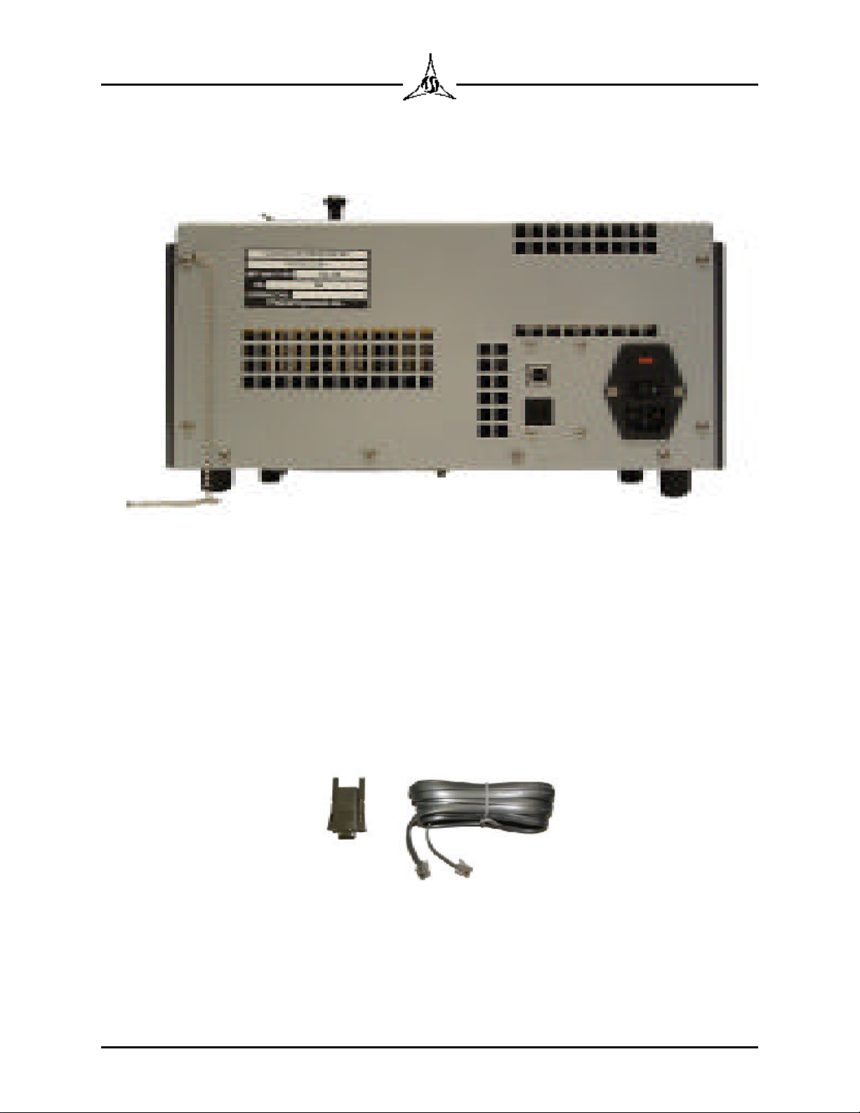
Figure 2.4 Printer Adaptor
To attach the external printer to the Model 225, plug the Printer Adaptor into the
25-pin D connector on the back of the Okidata 184. Tighten the thumb jacks.
Plug one end of the RJ-11 flat cable (telephone cable) into the Printer Adaptor.
The other end plugs into the RJ-11 jack on the back of the Model 225. Be sure
that nothing is attached to the USB jack on the Model 225.
Install tractor feed paper according to the Okidata 184 Printer Manual. Align the
paper perforation at the tear off edge of the viewing window. Be sure to follow
all instructions provided by Okidata regarding setup of this printer. The shipping
restraints holding the print head must be removed. Connect AC power to the
printer.
NOTE
The Okidata 184 must be ordered with the correct line
voltage input for your region of the world. The printer
does not contain a “universal” power supply nor a line
voltageselector. TRICORisnotresponsiblefordamages
caused by operating the Okidata 184 at the wrong line
voltage.
2.5 TMDAS (Option)
The Temper Meter Data Acquisition Software (TMDAS) is a Windows
application that accepts and interprets the external printer output from the 225,
plots smooth curves for display/printing and saves the data to a file where
multiple results can be analyzed. The TMDAS application and the external
printing feature of the Model 225 are both options that must be purchased.

2.6
TRICOR Systems Inc.
2.5 TMDAS (Option) (Cont'd)
Refer to the TMDAS manual for discussion of installing the software and
attaching the Model 225 to the PC. The discussion below, concerning PC
Configuration also describes the attachment of the Model 225 to a PC.
2.6 PC Configuration
The Model 225 is supplied with a Windows application that is used to configure
features. Not all the features shown in this manual are available on all Model
225 units. Some features are common to all units, while others are provided
only when originally purchased with the unit. A list of features which can be
configured is shown below:
•Set Real Time Clock/Calendar (Option)
•Set Power Line Frequency
•Adjust Sample Run Time(Option)
•Set User Text
•Extended Temperature Plotting(Option)
•Change CTU Offset
•Set Password
•Select CTU or Slope/Temperature
•Select Temperature Units
•Enable/Disable Internal Printer Auto-Print
•Enable/Disable External Printer Auto-Print (Option)
•Change Cooler Reference Temperature(Option)
•Change Heater Reference Temperature(Option)
Some, but not all of these features can also be changed using the menu on the
Model 225 itself. The Configuration Application does make setting these
features easier and more intuitive. See section 3 for menu descriptions.

2.7
TRICOR Systems Inc.
2.6.1 Software Installation
To install the configuration application, follow the procedure below:
NOTE
Youmusthaveadministratorprivilegestoproperlyinstall
this software on Windows NT, 2000 and XP.
1. Insert the installation CD into the CD-ROM drive of the PC.
2. If the auto-run feature does not work, navigate to the root directory
folder of the CD. Double click the file “SETUP.EXE”.
3. It is recommended that you accept the default installation options
provided by the install program. Simply press the “Enter” key to
accept the choices.
4. The program can be run by going to theStart menu and selecting
Programs | Model225 | Model225 Configure. The application
software can be run without the Model 225 attached, but the
operations are limited until there is communications established
between the PC and the unit.
5. If the USB connection is to be used on the Model 225, leave the
installation CD in the drive and skip down to section 2.6.3.
The communications between the PC and the Model 225 is handled over either
an RS232 serial port or a Universal Serial Bus (USB) port. The application
software will automatically attempt to find the unit if it is attached. Once
communications is established the buttons and the controls on the Configuration
dialog will become active. The choice of communications port is dependant on
the type of hardware resources available on the PC. Both methods provide the
same level of performance. Review the connection discussion below for proper
connection of the 225 to the PC.
2.8
TRICOR Systems Inc.
2.6.1 Software Installation (Cont'd)
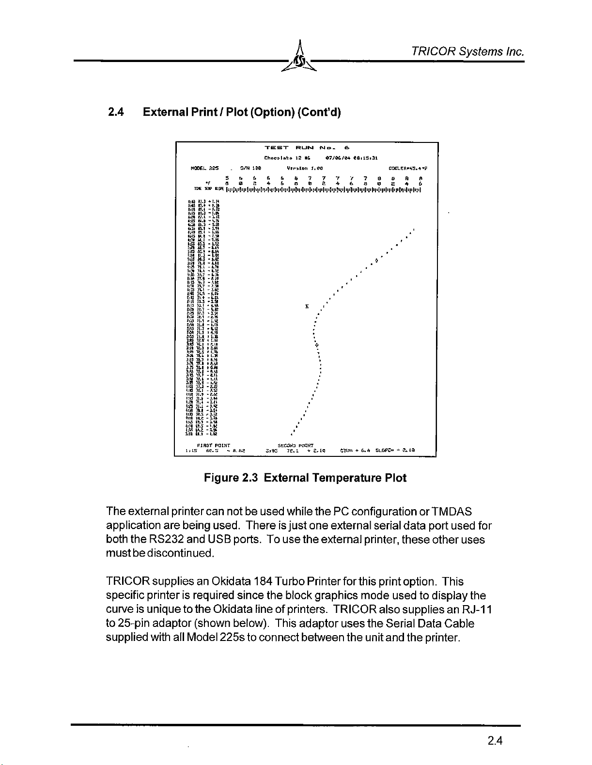
Figure 2.5 Serial and USB Connectors on Back of Model 225
2.6.2 RS232 Connection
The cabling required to communicate between the PC and the Model 225 is
provided. It consists of a 9-pin adaptor which attaches to the serial port of most
recent PCs. This adaptor accepts one end of the flat cable with RJ-11
connectors. The other end of the cable is plugged into the Model 225. The
black “phone” jack on the back of the unit is intended for the serial
communications.
Figure 2.6 RS232 Serial Cable

2.9
TRICOR Systems Inc.
2.6.2 RS232 Connection (Cont'd)
The cable provided is a standard “telephone” cable. If a longer cable is
required, a standard cable may be used as long as it is a 6-conductor cable.
Four-conductor cables will not work with the external printer.
WARNING
Thoughtheserialcablemaybethesameasthoseused
for telephone communications, the interface is not a
modemconnection. DonotplugtheModel225orthe9-
pin adaptor into a telephone network. They are
incompatible. Damage to the Model 225 or PC may
result.
2.6.3 USB Connection
The Model 225 may communicate with the PC using a USB interface. A
standard AB USB cable is required (not supplied). These cables have a length
limited by the USB specification. Extension cables violate the USB
specification and TRICOR Systems will not support equipment operated using a
USB cable longer than 6 feet.
IMPORTANT
DonotconnecttheModel225withtheUSBcabletothe
PCuntilinstructed to doso,below. If you arenotready
with the proper software, you may create difficulties
when connecting in the future.
USB is not supported (directly) by Windows 95, and may have incompatibilities
with early versions of Windows 98 and Windows NT 4.0. These are limitations
of the operating systems and not the Model 225.
For the USB communications to function, software drivers must be installed on
the PC. These drivers are provided on the installation CD that is provided. If
you have already installed the application software and have removed the CD
from the drive, you can prevent the auto-run installation from running again by
holding down the left shift key for several seconds while inserting the CD. If the
auto-run starts, simply cancel the operation.
2.10
TRICOR Systems Inc.
2.6.3 USB Connection (Cont'd)
With the Model 225 turned off, attach the unit to the PC using a USB cable. Be
sure Windows has started and is up and running. Turn on the power to the
Model 225. Within a few short seconds the Windows operating system should
recognize that new hardware has been attached. The dialog will prompt you to
load new software for this hardware. Navigate to the root directory of the CD
ROM drive. Press the next button to install the drivers. Depending on the
version of the operating system you may be asked to re-boot the PC. Follow the
directions provided by the operating system.
Run the Configuration application. It will search through all the available
resources on the PC in an attempt to find a connection to the Model 225. The
status bar of the application shows in the lower-left corner the communication
channel being used or currently searched.
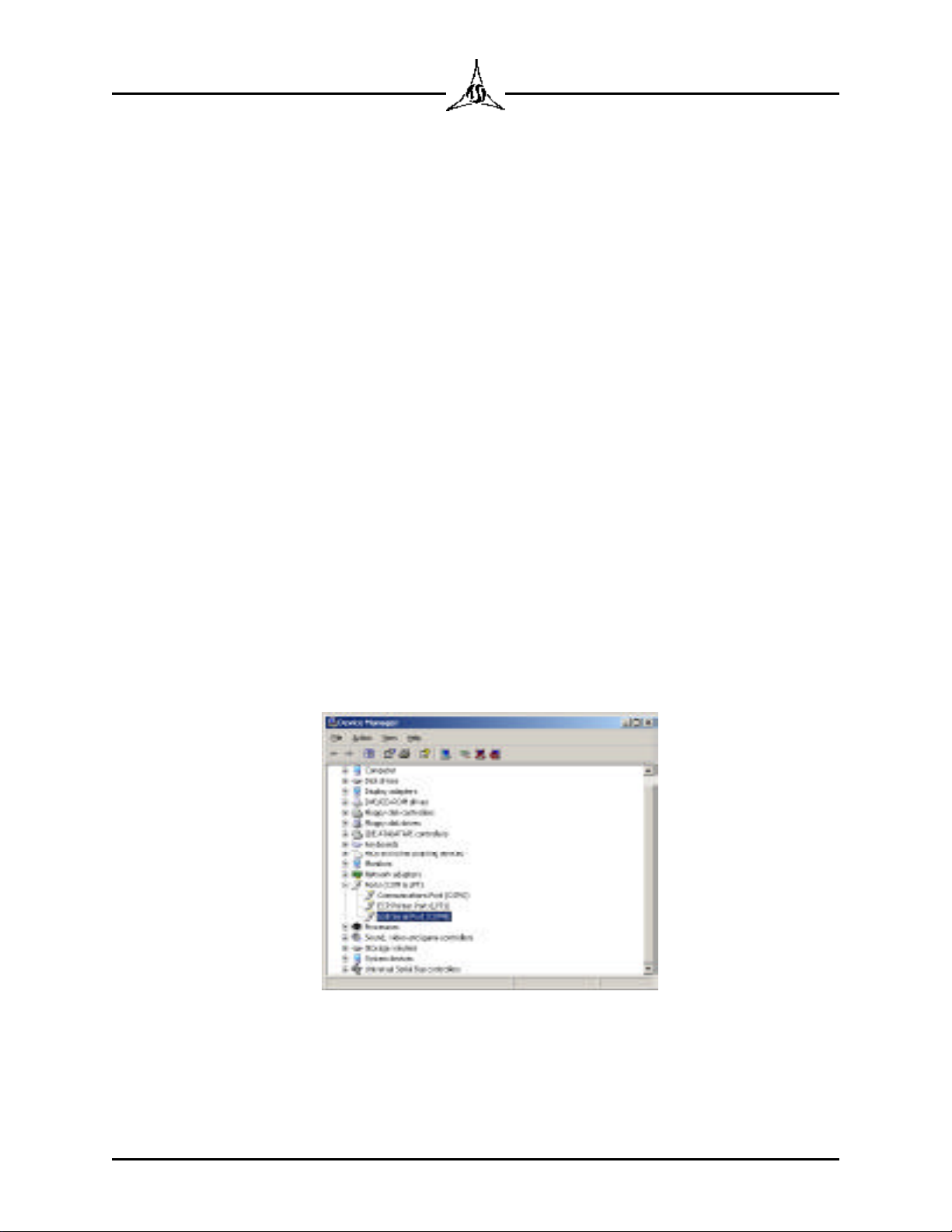
If there is trouble installing the USB drivers, the most likely cause are legacy
RS232 serial ports on the PC conflicting with the USB port designation. To
correct this problem, open the Windows Device Manager from the Control Panel
System folder. The newly installed USB connection should show up as a serial
port as shown below. Note, the port resource will not appear in this list if the
Model 225 is not attached and turned on. Be sure to close the Configuration
application.
Figure 2.7 Newly Installed USB Port

2.11
TRICOR Systems Inc.
2.6.3 USB Connection (Cont'd)
The currently selected COM channel is appended after the port name. This
channel selection should not be less than COM3. If it is, double click to edit the
port properties. Choose the Port Settings tab and press the Advanced button.
Figure 2.8 USB Port Settings
Change the port channel setting to some other value greater than COM4. Use
the Com Port Number drop down list box to choose the channel. Never select a
channel that is the same as an RS232 com port on the PC. Press the OK
buttons to back out with the new settings.
Figure 2.9 Advanced Port Settings
Turn off the Model 225 and reboot the Windows operating system. Wait for
Windows to again restart. Turn on the Model 225. Verify that the Configuration
application can communicate with the Model 225. The channel should match
that set in the driver configuration dialog. If problems persist, please call
TRICOR for assistance.
Table of contents
Other Tricor Measuring Instrument manuals


Popular Measuring Instrument manuals by other brands

Endress+Hauser
Endress+Hauser RIA15 operating instructions

ABB
ABB Aztec 600 user guide

Secomam
Secomam UviLine Connect Series operating manual

Fluidwell
Fluidwell F011-A user manual

VOLTCRAFT
VOLTCRAFT SL-300 instruction manual

Aquametro Oil & Marine
Aquametro Oil & Marine CONTOIL DN15 Mounting and operating instructions


