Trident TRIDENT 3U3I User manual

M A D E
S.A. au capital de 270 130 €
167, Impasse de la garrigue
F 83210 LA FARLEDE
Tél:+ 33 (0) 494 083 198 – FAX : + 33 (0) 494 082 879
E-mail: contact@made-sa.com - Web : www.made-sa.com
TRIDENT
NETWORK ANALYSER
USER’S GUIDE
August 2009
MADE-V_1._20

GU_TRIDENT_V_1_20_EN 2/47
CONTENTS
CHAPTER 1 - TRIDENT OVERVIEW..........................................................................................................................................................4
1.1 USING TRIDENT ............................................................................................................................................................................4
1.2 GENERAL DESCRIPTION .............................................................................................................................................................5
1.2.1 Functions..............................................................................................................................................................................5
1.2.2 Recordings............................................................................................................................................................................6
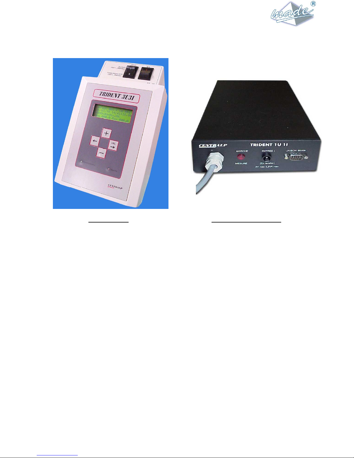
1.3 TRIDENT 3U3I ET 1U1I..................................................................................................................................................................7
1.4 MANUAL CONTENTS ...................................................................................................................................................................7
CHAPTER 2 - REFERENCE DOCUMENTS ................................................................................................................................................8
CHAPTER 3 - TERMINOLOGY ....................................................................................................................................................................9
3.1 ABREVIATIONS.............................................................................................................................................................................9
3.2 GLOSSARY .....................................................................................................................................................................................9
CHAPTER 4 - INSTALLATION & START-UP..........................................................................................................................................10
4.1 1ST START-UP...............................................................................................................................................................................10
4.1.1 Connection to the TRIDENT supply ..................................................................................................................................10
4.1.2 Turn on...............................................................................................................................................................................10
4.2 GENERAL RULES FOR THE USE OF THE USER INTERFACE................................................................................................10
4.3 COMMUNICATION WITH A PC ....................................................................................................................................................11
4.3.1 Communication configuration............................................................................................................................................11
CHAPTER 5 - DETAILS OF USE AND DESCRIPTION...........................................................................................................................13
5.1 ORGANISATION OF THE TRIDENT MENUS...............................................................................................................................13
5.2 CARRYING OUT AMEASUREMENT PROGRAM....................................................................................................................14
5.2.1 Typical measurement program ...........................................................................................................................................14
5.2.2 Programming TRIDENT....................................................................................................................................................15
5.2.3 Installation on site...............................................................................................................................................................21
5.2.4 Turn-On and checking connections ....................................................................................................................................23
5.2.5 Starting, Stopping and Ending a measurement program.....................................................................................................24
5.2.6 Results of a measurement program.....................................................................................................................................25
5.3 DIVERSE FUNCTIONS.................................................................................................................................................................29
5.3.1 Setting the Date & Time.....................................................................................................................................................29
5.3.2 Access Code .......................................................................................................................................................................29
5.4 MEASUREMENT PRINCIPLES OF TRIDENT............................................................................................................................30
5.4.1 Sampling.............................................................................................................................................................................30
5.4.2 Calculation of the 20ms RMS values and fault detection...................................................................................................30
5.4.3 Calculation of slow variations ............................................................................................................................................31
5.4.4 Calculation of the frequency...............................................................................................................................................32
5.4.5 Management of the slow overvalues and of their recording. ..............................................................................................32
5.4.6 Maxima of I and P (except 1U, 3U et 3U3V).....................................................................................................................32
5.4.7 Management of overfrequencies.........................................................................................................................................32
5.4.8 Calculation of voltage imbalances (TRIDENT 3U3V).......................................................................................................33
CHAPTER 6 - MAINTENANCE & TROUBLESHOOTING.....................................................................................................................34
CHAPTER 7 - DETAILLED TECHNICAL FEATURES...........................................................................................................................35
7.1 TEMPERATURES .........................................................................................................................................................................35
7.2 PHYSICAL FORM.........................................................................................................................................................................35
7.3 SUPPLIES ......................................................................................................................................................................................35
7.4 MEASUREMENT INPUTS &ACCURACIES..............................................................................................................................36
7.5 STANDARDS ................................................................................................................................................................................37
CHAPTER 8 - HARMONICS : SUPPLEMENT TO THE TRIDENT USER’S MANUEL .....................................................................38
8.1 OVERVIEW OF THE APPLICATION « HARMONICS » FOR TRIDENT..................................................................................38
8.2 DEFINITIONS................................................................................................................................................................................38
8.3 DETAILLED DESCRIPTION........................................................................................................................................................40
8.4 INSTALLATION AND START-UP SEE CHAPTER 4........................................................................................................................40
8.5 DETAILS OF USE AND DESCRIPTION......................................................................................................................................40
8.5.1 TRIDENT menu organisation.............................................................................................................................................40
8.5.2 Carrying out a measurement program.................................................................................................................................41

GU_TRIDENT_V_1_20_EN 3/47
8.5.3 Diverse functions................................................................................................................................................................47
8.5.4 Measurement principles of TRIDENT H...........................................................................................................................47
8.6 MAINTENANCE AND TROUBLESHOOTING SEE THE TRIDENT 3U3I MANUAL.....................................................................48
8.7 DETAILLED TECHNICAL FEATURES SEE TRIDENT 3U3I MANUAL. ....................................................................................48
8.7.1 Measurement inputs and accuracies See TRIDENT 3U3I manual. ....................................................................................48

GU_TRIDENT_V_1_20_EN 4/47
CHAPTER 1 - TRIDENT OVERVIEW
1.1USING TRIDENT
The TRIDENT range includes the following products:
TRIDENT “Blind” including:
Trident 1U
Trident 1U1I
Trident 3U
Trident 3U3I
TRIDENT standard:
Trident 3U
Trident 3U3V
Trident 3U3I
With a harmonic option on the TRIDENT 3U3I.
Remark:This note describes the use of any product in the TRIDENT range.
The display functions and use of the keyboard that are described here do not apply to a
“Blind” TRIDENT.
Similarly, descriptions of the measurement functions of triphase units are to be considered in
monophase for versions 1U and 1U1I.
TRIDENT is used to perform measurement programs on three phase & single-phase low voltage (400V) and
medium voltage (11 or 20kV.) electrical networks using measurement sensors.
The device has only low voltage inputs.
TRIDENT 3U3I /I is intended for use with current clamps having a current output of 1A or 5A.
TRIDENT 3U3I /V is intended for use with current clamps having a voltage output of 1V to 5V.
During a program, it records:
Voltage faults, including those on the Neutral/Earth,
A running record of the RMS values of the voltages and currents, as well as the total active power,
The durations of frequency out-of-limits (measured on the phase 1 voltage input),
The durations of out-of-limits of the mean values of the voltages,
Five date stamped maxima of current in 1 sec. values and P in mean values (for the product of U & I).
TRIDENT has a local user interface, consisting of an LCD display of 4 lines of 20 characters each and 4
buttons (except, of course, for the « Blind » versions).
Communication with a PC is made via a series connection RS232 (RS485 is optional). The WINTRID PC
software is a necessary complement for TRIDENT which enables the study and analysis of the measurements
made by the equipment.

GU_TRIDENT_V_1_20_EN 5/47
1.2 GENERAL DESCRIPTION
1.2.1 Functions
TRIDENT is a portable recorder, light and field-tested, which records & analyses the voltage,
current and power on single and three phase electrical networks.
TRIDENT can:
Measure and assess the voltage quality according to the EN 50160 Standard: "Voltage
characteristics of the electricity supplied by public distribution networks ", notably:
Slow voltage variations,
Brief overvoltages,
Brief dips,
Brief & long interruptions,
Frequency variations,
Overvoltages between neutral & earth (except monophase products).
Record the evolution of the continuous measurements of the 3 currents and the 3 voltages taken
simultaneously at the same measurement point,
Carry out an analysis of the active power consumption at this point of the network.
TRIDENT is supplied with the WINTRID display and configuration software, which runs on the
WINDOWS 3.11, 95, 98, NT and XP versions.
WINTRID enables :
The configuration of the computer,
The configuration of TRIDENT,
The consultation of the instantaneous measurements,
The sampling and graphical representation of the slow variations in voltage, current and power
superposed on the voltage events,
The preparation of a list of all events and their characteristics,
A statistical analysis of the events,
Rapid and simple printing of reports in colour,
The transfer of data to other applications (spread-sheets, word processing...).

GU_TRIDENT_V_1_20_EN 6/47
1.2.2 Recordings
The quality of the 3 voltages, either simple (i.e. Phase to Neutral in a star network) or line (i.e.
between phases in a delta network), is continuously monitored by TRIDENT.
Slow Variations of Amplitude:
The number of times the mean voltage passes the high & low thresholds is totalled.
Rapid Variations of Amplitude:
TRIDENT can sense and record any voltage variation with a time resolution of 2ms.
TRIDENT records 3 types of faults according to the threshold passed by the voltage:
overvoltages,
voltage dips,
Long interruptions,
Brief interruptions.
A minimum duration threshold, programmed by the user, is used to avoid recording very brief
events.
A voltage fault is recorded with:
start time & date,
duration,
type,
phase,
the mean voltage during the fault,
a 10ms peak voltage during the fault,
the 1 second values of the 3 U (or V) and 3 I before the fault,
the 1 second values of the 3 U (or V) and 3 I after the fault,
Overvoltage between Earth & Neutral :
The voltage between neutral & earth is measured continuously over 20ms rolling each 2ms.
Crossing a threshold starts the recording of an Earth/Neutral overvoltage, having the same
characteristics as for a voltage fault.
Frequency monitoring :
The frequency is continuously measured in the form of a 10 second mean on the phase 1 voltage.
Crossings of a high or low threshold are totalled.
Power and Current Maxima:
The 5 highest values of the currents (1 second mean, all phases together) are recorded & dated.
The 5 highest values of the active total power are recorded & dated.

GU_TRIDENT_V_1_20_EN 7/47
1.3 TRIDENT 3U3I ET 1U1I
TRIDENT 3U3I TRIDENT 1U1I « BLIND »
1.4 MANUAL CONTENTS
The reference documents listed in CHAPTER 2 and CHAPTER 3 contain the glossary of specific terms.
CHAPTER 4 gives the procedure to follow for the first Start-Up of TRIDENT 3U3I. CHAPTER 5 describes
in detail the use of TRIDENT on site and gives the list of the different data available.

GU_TRIDENT_V_1_20_EN 8/47
CHAPTER 2 - REFERENCE DOCUMENTS
WINTRID software manual: LOG PC 0006
Voltage Quality:
EN 50160 : Caractéristiques de la voltage fournie par les réseaux publics de distribution.
Security Regulations :
EN 61010-1, édition 1993, plus amendement A2 : Règles de sécurité pour appareils électriques de
mesurage, de régulation et de laboratoire.
Electromagnetic compatibility:
NF EN 50 081-2, décembre1993 : norme générique émission. Partie 2 : environnement industriel.
EN 55 011 : limites et méthodes de mesure des caractéristiques de perturbations électriques des
appareils industriels, scientifiques et médicaux (ISM) to fréquence radioélectrique.
Susceptibility to perturbations :
NF EN 50 082-2, juin 1995 : norme générique immunité. Partie 2 : environnement industriel.

GU_TRIDENT_V_1_20_EN 9/47
CHAPTER 3 - TERMINOLOGY
3.1ABREVIATIONS
HTA: high voltage used for electrical supply, with anominal RMS ranging from 1kV to 50Kv
HTB: high voltage used for electrical supply, with a nominal RMS superior to 50kV
LV : Low Voltage electrical supply, with a nominal RMS value ofless than 1kV.
TRIDENT only directly measures LV with a the nominal RMS value of less than 400V.
VT : Voltage transformer, placed between the high voltage to be measured and the TRIDENT inputs.
CT : Current transformer. In this document clamps with current outputs (for TRIDENT 3U3I /I) and
clamps with voltage outputs (for TRIDENT 3U3I /U) have the same abbreviation.
3.2GLOSSARY
Voltage dips: rapid and temporary voltage drop measured below the programmed threshold,
followed by a re-establishment of the voltage, or an interruption.
Overvoltage: temporary voltage increase, slow or rapid, measured above the programmed threshold.
Brief interruption : disappearance or large voltage drop measured during a brief instant. According to the
EN50160 standard, a brief interruption is less than 3mn.
Long interruption : disappearance or large drop of voltage. According to the EN50160 standard, a long
interruption is over 3mn.
Rapid Variation, voltage fault : abrupt variation of the voltage RMS value measured over at least
one cycle (rise, dip or break) followed by a re-establishment of the
voltage or a change to another type of rapid variation. A rapid
variation over the detection thresholds of TRIDENT is considered as
a voltage fault.
Slow Variations: variations of the mean RMS values of the physical parameter measured (voltage,
current or power).

GU_TRIDENT_V_1_20_EN 10/47
CHAPTER 4 - INSTALLATION & START-UP
4.1 1st START-UP
4.1.1 Connection to the TRIDENT supply
On reception, TRIDENT should be connected close to the PC which will serve as the workstation
for the recordings, in order to open communication with the WINTRID software.
For the 1st start-up, it is sufficient to insert the plug of the power cable supplied with the equipment
in the auxiliary power socket and the other end in the mains 50Hz, 230V A.C.
The supply mode selected must be Auxiliaire 230V
,10VA max.
On site, it uses the voltage measurement inputs as a source of supply. This supply option is
explained in paragraph 5.2.3 Installation on site and in this case the switch should be in the position
Entrées mesures N-V1 230V
,10VA max.
4.1.2 Turn on
The device is turned on by switching the marche/arrêt switch to position I. Turn the device
offsimply by inversing the switch or in the absence of an alternative supply when the internal
battery is discharged.
Upon start-up, the red light is lit and the screen shows :
T
R
I
D
E
N
T
3
U
3
I
/
I
V
1
.
7
N
O
T
R
E
C
O
R
D
I
N
G
3
0
/
1
0
/
1
9
9
8
1
1
:
1
0
:
2
4
M
A
D
E
S
A
It shows the type of TRIDENT, 3U3I, as well as the software version.
This screen also indicates the internal date and time of TRIDENT. This time can be slightly
different from the correct time because of possible drift during storage.
Pressing the button VALbrings up the main menu.
4.2 GENERAL RULES FOR THE USE OF THE USER INTERFACE
On the front face of TRIDENT is a 4 line, 20 character display, as well as a 4 key keyboard:
+(plus),
-(minus),
(left arrow),
(right arrow, VAL)
This group is enough to configure or operate TRIDENT.
All the keys autorepeat if held down.
Generally :
The keys +/- are used to move an arrow on the screen, or to modify the value of a figure being entered
(underlined by the cursor).
The key can, depending on the position of the cursor, move to the digit or field following, or
validate a page and move to the following page.
The key can, depending on the position of the cursor, move to the preceding digit or field, or return

GU_TRIDENT_V_1_20_EN 11/47
to the preceding page.
To enter a value :
Numerical entries are made by moving the cursor (underlining the relevant) using the 2 arrows.
If a figure is underlined by the cursor, the keys + & - are used to increment or decrement this figure.
Sometimes the possible values are pre-defined (communication speeds for example), in which case the
keys + or –move in the list of values.
Incorrect entry :
If a value is entered incorrectly (outside the permitted limits for example), when the number is validated,
TRIDENT returns the cursor to the beginning of the field.
4.3 COMMUNICATION with a PC
4.3.1 Communication configuration
As delivered, TRIDENT is configured with the following communication parameters, identical to
those of WINTRID when it is installed :
Communication speed : 9600 bauds,
Adress N°: 001,
Communication protocol: RS232.
To check or modify these parameters, enter the menu communication configuration.
Pressing the VALkey opens the main menu from the opening screen.
M
A
I
N
M
E
N
U
D
i
r
e
c
t
M
e
s
u
r
e
m
e
n
t
-
-
>
C
o
n
f
i
g
u
r
a
t
i
o
n
C
o
n
s
u
l
t
a
t
i
o
n
If the device is currently measuring (that is, during a measurement program), the 2nd choice,
Configuration, is replaced by program stop. Thus the measurement must be stopped before
configuring TRIDENT.
With the keys + or - select the menu Configuration. Pressing the VALkey opens this menu, once
the arrow is opposite Configuration.
Next select the menu Communication.
C
o
n
f
i
g
u
r
a
t
i
o
n
P
r
o
g
r
a
m
-
-
>
C
o
m
m
u
n
i
c
a
t
i
o
n
I
n
t
e
r
n
a
l
C
l
o
c
k

GU_TRIDENT_V_1_20_EN 12/47
The following screen appears :
C
O
N
F
I
G
.
C
O
M
.
S
p
e
e
d
:
9
6
0
0
B
a
u
d
s
A
d
d
r
e
s
s
:
0
0
1
P
o
r
t
:
R
S
2
3
2
Speed. The communication speed can be modified using the + and - keys. Possible values: 1200,
2400, 4800 or 9600 bauds.
Address. The address of TRIDENT can vary from 1 to 255 and must be identical to that
programmed in WINTRID. This address system enables communication with several
TRIDENTs connected on the same network (type RS485, for example). Only the one
with the corresponding address will respond.
Port. The communication protocol cannot be modified (RS232 standard, RS485 on request).
Confirm the various fields. The correct operation of the communication with WINTRID can then be
checked, see the WINTRID documentation to carry out this test.
The green lamp communication lights each time the device receives a correct information
packet intended for it. This enables simple verification of the communication and is a
troubleshooting aid.
If there is a communication failure, check:
That TRIDENT is properly connected to the correct PC port with the cable provided with
TRIDENT,
That the communication parameters are all identical,
That TRIDENT is supplied by an external supply (TRIDENT does not communicate when it is
powered by its back-up battery).
Note : The communication is 8 bits, no parity, with a start bit and a stop bit.

GU_TRIDENT_V_1_20_EN 13/47
CHAPTER 5 - DETAILS OF USE AND DESCRIPTION
5.1 ORGANISATION of the TRIDENT MENUS
The TRIDENT menus follow the arborescence below when the device is not measuring :
Welcome Not Recording
Direct Measurements
Consultation of the instantaneous values (2 pages)
Configuration
Configuration of the next program
Confirmation
Program parameters (7 pages)
Time & Date of start & finish
Parameters of communication
Setting the internal clock
Consultation of the results of the last program
Consultation of the faults
Total number n of faults
Detail of each fault (n pages)
Consultation of the slow variations
Overvoltages V1, V2 and V3 (3 pages)
Maxima of I
Maxima of P
Frequency out-of-limits
Consultation of the program parameters (6 pages)
When a program is started the configuration menu is no longer accessible. It is replaced by the option of
stopping the running program :
Welcome Program (program running)
Direct Measurements
Program Stop
Consultation of the results of the running program

GU_TRIDENT_V_1_20_EN 14/47
5.2 CARRYING OUT A MEASUREMENT PROGRAM
5.2.1 Typical measurement program
Before beginning a measurement program, the device must be programmed with the correct
measurement parameters.
Parameters can be set in several ways:
The device can be programmed with the help of the WINTRID software that offers a user-friendly
interface. As all measurement operations can be programmed in advance, the device can be
programed at the measurement site or elsewhere, for example close to the office PC.
In the case of a deferred start to the program, TRIDENT must be installed with all its connections
before the programmed start time in order avoid recording false events (notably interruptions).
TRIDENT can also be programed once installed, either with WINTRID, or with the use of its local
interface.
To help with the local interface, TRIDENT has in memory two Standard measurement programs
one of which can be installed at the start of a program. This avoids the need for full programming in
detail. These standard programs can be modified to suit the requirement with the help of the
WINTRID software.
Before starting the program, TRIDENT will ask for confirmation of the clamp outputs (voltage &
current) and dates of the start and end of the program.
A program can have a predefined end time or can be of indeterminate length.
Once the connections are in place, the instantaneous measurements can be verified to confirm the
correct connection of the device.
The measurement program starts as the internal clock reaches the programmed time, or if that time
is passed when the device is turned on.
The program continues :
either until the user sends a stop command by WINTRID, or by the local user-interface,
or until the chosen end of the program, if there is one.
In case of an interruption of the program (battery exhausted, M/A switch,...), the program restarts at
the re-supply.
The results summary of the measurement program can be obtained during the progress of the
program if TRIDENT is still connected to the PC. Otherwise at the end of the measurement
program TRIDENT is connected to the PC. The transfer begins automatically and the analysis is
then performed by WINTRID.
The main results of the program in progress can also be seen using the local interface.

GU_TRIDENT_V_1_20_EN 15/47
5.2.2 Programming TRIDENT
TRIDENT can be completely configured using its local interface, in the same way as using
WINTRID.
For this, in the menu configuration, choose Program and enter:
C
O
N
F
I
G
U
R
A
T
I
O
N
M
E
N
U
-
-
>
P
r
o
g
r
a
m
C
O
m
m
u
n
i
c
a
t
i
o
n
I
n
t
e
r
n
a
l
C
l
o
c
k
TRIDENT warns you that the last program will be erased permanently from the memory. Check
carefully that this program has been transferred to WINTRID.
A
T
T
E
N
T
I
O
N
!
!
!
T
h
e
m
e
m
o
r
y
w
i
l
l
b
e
e
r
a
s
e
d
.
C
o
n
t
i
n
u
e
?
N
O
V
a
l
i
d
a
t
i
o
n
-
>
The +/- keys move between NO & YES, and the VALkey confirms the choice.
Confirm with YES to enter into the configuration menu.
There are 7 successive pages of configuration. They are all numbered and you can return at all times
to the entries on the previous page with the key.
Choice of a standard or manual configuration:
C
O
N
F
I
G
.
P
R
O
G
R
A
M
1
/
7
S
t
1
:
L
I
b
e
l
l
e
0
1
-
-
>
S
t
2
:
L
I
b
e
l
l
e
0
2
C
o
n
f
i
g
.
m
a
n
u
a
l
The user must choose between one of the 2 Standards (of which the name and parameters have been
initialised by the WINTRID software), or the local configuration of all parameters.
The standards contain all parameters that will be required subsequently in the manual configuration.
Their names are those chosen at the time of their modification in WINTRID.
If one of the 2 Standards is chosen, it is only necessary to enter or validate the types of TC and TP
and the times and dates of the start and end of the program.

GU_TRIDENT_V_1_20_EN 16/47
Upon delivery, TRIDENT 3U3I contains the following two Standards:
1) Measurement of simple voltages at Low Voltage.
Standard Name: bt_simple
Voltage Clamps TP : 1V / 1V.
Current clamps TC
For TRIDENT 3U3I /I : 500 A / 5 A.
For TRIDENT 3U3I/U : 100 A/ 1V.
Type of voltage measurement : simple.
Nominale primairy voltage : 230V.
Integration time for slow variations: 10 mn.
Thresholds for slow variations.
Swells : +6 % (243,8 V)
Dips : -10% (207V)
Voltage faults :
High threshold : +6% (243,8V)
Low threshold : -6% (216,2 V)
Interruption threshold : -80 % (46V)
Length of long interruption : 180s. (3 minutes)
Minimum fault variation : 10ms
Threshold neutral/earth: 5 V
Frequency threshold :
High: 50,5 Hz
Low : 49,5 Hz
2) Mesurement of line voltages at Medium Voltage.
Standard name : HTA_compos
Voltage clamps TP : 20 000V / 100V.
Current clamps TC :
For TRIDENT 3U3I /I : 1000 A / 5 A.
For TRIDENT 3U3I/U : 100 A/ 1V.
Type of voltage measurement : composit.
Nominale primaire voltage : 20 000V.
Integration time for slow variations: 10 mn.
Thresholds for slow variations.
Swells : +10 % (22 000 V)
Dips : -10% (18 000V)
Voltage faults :
High threshold : + 4 % (20 800V)
Low threshold : - 6 % (18 800 V)
Interruption threshold : - 80 % (4 000V)
Length of long interruption : 180s. (3 minutes)
Minimum fault variation : 10ms
Threshold neutral/earth: 5 V
Frequency threshold :
High : 50,5 Hz
Low : 49,5 Hz
Choose one of the two Standards or the manual configuration, and then validate to advance to
the 2nd configuration page.

GU_TRIDENT_V_1_20_EN 17/47
Characteristics of the network to be measured :
C
O
N
F
I
G
.
P
R
O
G
R
A
M
2
/
7
T
V
:
2
0
0
0
0
/
1
0
0
.
0
V
C
T
:
1
0
0
0
A
1
.
0
V
S
i
m
p
l
e
V
n
=
1
5
0
0
0
.
0
V
TRIDENT 3U3I makes the measurements directly on the network or via voltage transformers (TP)
and current transformers (TC)
Voltages :
TRIDENT can measure up to 440 V between phases and between phase and neutral. To
configure the voltage clamps it is necessary to enter or validate the values of the primary and
secondary.
The primary can be between 1 and 99999V (without decimal).
The secondary can be between 1 and 999,9V.
NOTE : the transformation ratio does not apply to the earth/neutral voltage.
Currents :
TRIDENT 3U3I /I accepts only current clamps with current output. It can measure directly up to
6A per phase. To configure the CTs it is necessary to enter or validate values for the primary and
the secondary.
The primary of the CTs can be between 1 and 9999A.
The secondary is 1 or 5A.
TRIDENT 3U3I /I is calibrated to measure 5A inputs. If you choose 1A, the measurement
precision will be slightly degraded.
The neutral current is calculated and not measured.
TRIDENT 3U3I /U accepts only clamps with current output. It can measure directly up to 5V
per phase. To configure the CTs it is necessary to enter or validate values of the primary and the
secondary.
The primary of the CTs can be between 1 and 9999A.
TRIDENT 3U3I /U is calibrated to measure from 5V inputs. If you choose a lower value, the
measurement precision will be slightly degraded.
TRIDENT carries out different measurements according to the network selected :
simple voltages : TRIDENT gives values of the voltages between phase and neutral and
makes all events calculations according to these values. In the absence of a neutral, an
internal neutral is recreated by a high impedance resistive bridge.
line voltages : TRIDENT gives real voltage values between phases U12, U23, U31 and does
all events calculations according to these values.
monophase (simple V1 voltage only) : TRIDENT makes measurements between V1 and
neutral and of the current I1 and ignores other channels.
Nominal voltage :
The nominal voltage of the primary. Its value can be between 50V and 99999,9V and must be
expressed as the voltage between phase and neutral Vn if simple or monophase has been
selected, otherwise as line voltage Un.
This value is important because all thresholds are referenced to it.
Recommendation: if the real value is different from the theoretical nominal voltage, it is
worthwhile to enter the real value after having consulted the measurements taken by TRIDENT
after its installation.
After having checked the modifications, validate them.
If one of the two standards has been chosen, validate all the values to move directly to the last
page of program configuration (start date). Otherwise advance to the 3rd configuration page.

GU_TRIDENT_V_1_20_EN 18/47
Measuring slow variations:
C
O
N
F
I
G
.
P
R
O
G
R
A
M
3
/
7
I
n
t
E
g
S
l
o
w
V
a
r
s
0
1
m
n
T
h
r
e
s
R
:
+
0
3
%
(
2
3
6
.
9
V
)
T
h
r
e
s
D
r
:
-
0
3
%
(
2
2
3
.
1
V
)
Select here the integration period of the slow voltage, current & power variations, and also the
thresholds of swells and sags. High thresholds determine limits over which the slow variations must
not pass, in accordance with the EN50160 standard.
Integration time for means :
This value can be between 1 and 60mn.
TRIDENT can record continuously 28 days of measurements with a 10 mn integration period. If
a longer period is chosen, the autonomy of TRIDENT changes.
Examples :
Period 3mn, TRIDENT records a little over 8 days.
Period 30 mns, TRIDENT records for nearly 3 months.
The TRIDENT memory is “circular”, that is to say that when it is full, the measurement program
continues, but the oldest recordings are replaced by the most recent.
Swells threshold : ThresholdH
This is entered as a percentage of the nominal voltage. This threshold can be between 3 and 30%
of the nominal voltage.
Sags threshold: ThresholdCr
This can be between -3 and -80% of the nominal voltage.
When one of the 2 thresholds is modified, the corresponding voltage (simple or line according to
the type of network selected) is displayed for information. If the nominal voltage is superior to
760V , TRIDENT displays voltages in kV.
After having checked the modifications, validate each one and advance to the 4th config. page.
Measurement of voltage faults:
C
O
N
F
I
G
.
P
R
O
G
R
A
M
4
/
7
R
i
s
e
:
+
0
9
%
(
2
5
0
.
7
V
)
F
a
l
l
:
-
0
5
%
(
2
1
8
.
5
V
)
I
n
t
e
r
.
:
-
8
7
%
(
0
2
9
.
9
V
)
Here the quick variation parameters, thresholds of rises, dips and interruptions are configured.
Overvoltage thresholds determine limits over which the rapid variations (instantaneous) should not
pass, in accordance with the norm EN50160.
TRIDENT records up to 1000 faults within the limit of the circular memory: when it is full, the
measurement program continues, but the oldest records are replaced by the most recent.
Otherwise TRIDENT has a fault counter that memorizes the total number of faults detected
independently of the available memory, which enables better appreciation of the state of the
network during the program.

GU_TRIDENT_V_1_20_EN 19/47
NOTE : this memory is completely independent from the memory for the slow variations and can
therefore «rotate » before or after the other. WINTRID will take this phenomenon into
account for data analysis.
The high threshold can be between +3 and +30% of the nominal voltage.
The low threshold can be between -3 and -80% of the nominal voltage.
The interruption threshold (break.) can be between -80 and -95% of the nominal voltage.
The entry interface is similar to that for the slow variations.
After having checked the modifications, validate each one and advance to the 5th config. page.
C
O
N
F
I
G
.
C
A
M
P
A
G
N
E
5
/
7
T
h
r
e
s
I
b
/
I
l
:
0
1
2
.
0
s
T
h
r
e
s
d
u
r
a
t
:
0
0
1
0
m
s
T
h
r
e
s
e
a
r
t
h
:
0
0
5
V
Duration threshold between brief and long interruptions (Threshold Ib/Il) : entered in 0,1 second.
TRIDENT sorts interruptions between long and brief according to the threshold that has been
programmed. All interruptions whose length is superior to this threshold will be considered long
and the others brief.
This threshold can range from 0,1 to 999,9 secs.
Minimum fault duration (Threshold duration) : entered in milliseconds.
TRIDENT will ignore all faults below this threshold.
This threshold can be between 10 and 9990ms.
Earth/neutral fault (Threshold earth) : entered in volts.
Passing this threshold causes the recording of a Rise of Earth voltage.
This threshold can be between 5 and 400V whatever the ratio of transformation of the TPs.
The entry of 000 inhibits the detection of earth/neutral faults and can thus save memory.
After having checked the modifications, validate them and advance to the 6th configuration page.
Frequency measurement :
C
O
N
F
I
G
.
P
R
O
G
R
A
M
6
/
7
F
r
e
q
u
e
n
c
y
:
H
i
g
h
T
h
r
e
s
h
:
5
3
.
1
H
z
L
o
w
T
h
r
e
s
h
:
4
8
.
7
H
z
Here the thresholds of variation of the frequency of the network are configured.
TRIDENT measures the frequency continuously and records the time during which the frequency
passes the thresholds in accordance with the norm EN50160.
These times are memorized in the successive weekly totals. For every week of the measurement
program, a counter indicating the time of out-of-limits in seconds is updated, for up to 10 counters.
If the program lasts more than 10 weeks, the last counter is incremented until the end of the
program, thus this ceases to be a weekly counter.
The threshold of frequency rise can be between 50.1 and 55Hz.
The threshold of frequency decrease can be between 45 and 49.9Hz.
The frequency is measured on the phase 1, if V1 > 10V.
After having checked the modifications, validate each one and advance to the 7th config. page.

GU_TRIDENT_V_1_20_EN 20/47
Date & time of start & finish of the measurement program :
C
O
N
F
I
G
.
P
R
O
G
R
A
M
7
/
7
S
0
1
/
0
1
/
2
0
0
0
0
0
:
0
0
:
0
0
E
0
1
/
0
1
/
2
0
0
0
0
0
:
0
0
:
0
0
The hour and the date of the start (S) and end (E) of the program must be entered. By default these
are the current time.
If they are not modified, the program will start immediately after the last field on this page has been
validated.
If the end date & time is identical or previous to that of the beginning, the program is of unlimited
length and will end only when terminated by the operator.
If the start date is before the present date, the program will start immediately after the last field has
been validated.
If the start date is later than the current date, TRIDENT will wait until this date to start the program.
The device can be turned off and moved, this parameter remains in the memory.
This manual suits for next models
1
Table of contents
Other Trident Measuring Instrument manuals
Popular Measuring Instrument manuals by other brands

Full Gauge Controls
Full Gauge Controls EnergyLOG plus quick start guide

Safeside
Safeside R-3D2 Series Installation and operating instructions

Steinberg Systems
Steinberg Systems SBS-SF-1000 user manual

Anritsu
Anritsu MS2830A-040 Product brochure

SMARDY
SMARDY TDS-3 manual

LaserLiner
LaserLiner ZipLevel Operation manual