3Trident Audio Developments | Hi-Lo Dynamic Filtering User Manual 4Trident Audio Developments | Hi-Lo Dynamic Filtering User Manual
Hi-Cut Dynamic Tracking continued
Using the TRACK SIGNAL function enables the Hi-Cut filter to be used
for dynamic noise reduction. This
is a technique which relies on the
psychoacoustic eect of ‘masking’,
in which a louder signal will cover
up
a quieter signal of the same
frequency. In this mode, the cuto
frequency
tracks dynamically the high
frequency content of the music, with
the FRE-
QUENCY control setting the frequency to which the filter will close down
in the absence of any high frequency content.
With a noisy signal applied (e.g. from analogue tape or other material
with a high background noise content), start with the FREQUENCY con-
trol at maximum (fully clockwise) and back o the control until the noise
just disappears.
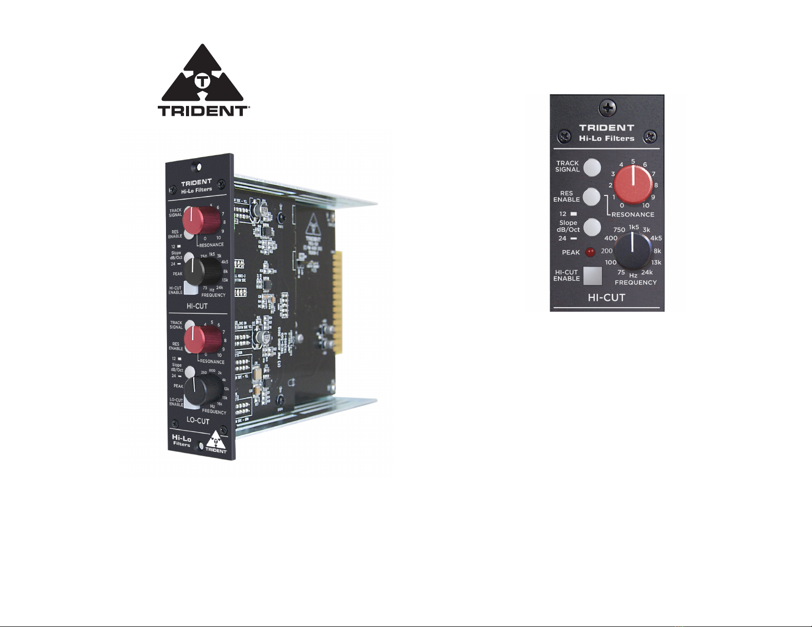
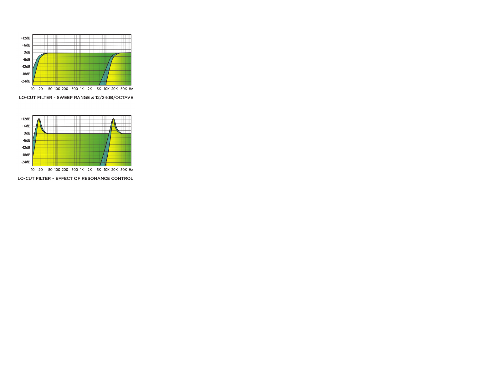
The Lo-Cut
This is a sweepable high pass filter with unity
gain in the selected pass band and select-
able (12dB per octave or 24dB per octave)
roll-o outside of the pass band. Cut o fre-
quency can be set manually, anywhere from
15Hz to 16kHz.
In addition, a RESONANCE control can be
switched into circuit, to introduce a resonant
peak, which is independent of the selected
cut-o frequency, which can be varied from zero
to approximately +12dB. At maximum set-
ting, resonance stops short of self-oscillation.
A LOW-CUT ENABLE switch allows each indi-
vidual frequency band or filter to be assessed,
whilst a red PEAK warning indicator will illuminate at approximately
+16dBu, approximately 12dBu below clip-ping. To allow adequate head-
room, avoid boosting the signal by more than an amount which just caus-
es this LED to flash on occasional peaks.
Lo-Cut Dynamic Tracking
Using the TRACK SIGNAL function, enables the Lo-Cut filter to be used
for dynamic hum or rumble reduction. This is a technique which relies
on the psychoacoustic eect of ‘masking’, in which a louder signal will
cover up a quieter signal of the same frequency. In this mode, the cut-o
fre-quency tracks dynamically the low frequency content of the music,
with the FREQUENCY control setting the frequency to which the filter
will open up in the absence of any low frequency content.
With a noisy signal applied (e.g. from a record deck or other material with
a high background noise content), start with the FREQUENCY control at
min-imum (fully anticlockwise) and advance the control until the hum or
rumble just disappears.
Use of higher resonant set-
tings will result in the move-
ment of the filter becoming
audible and indeed, combined
with the lower settings of the
FREQUENCY control, this can
be the basis of some unique
special eects.
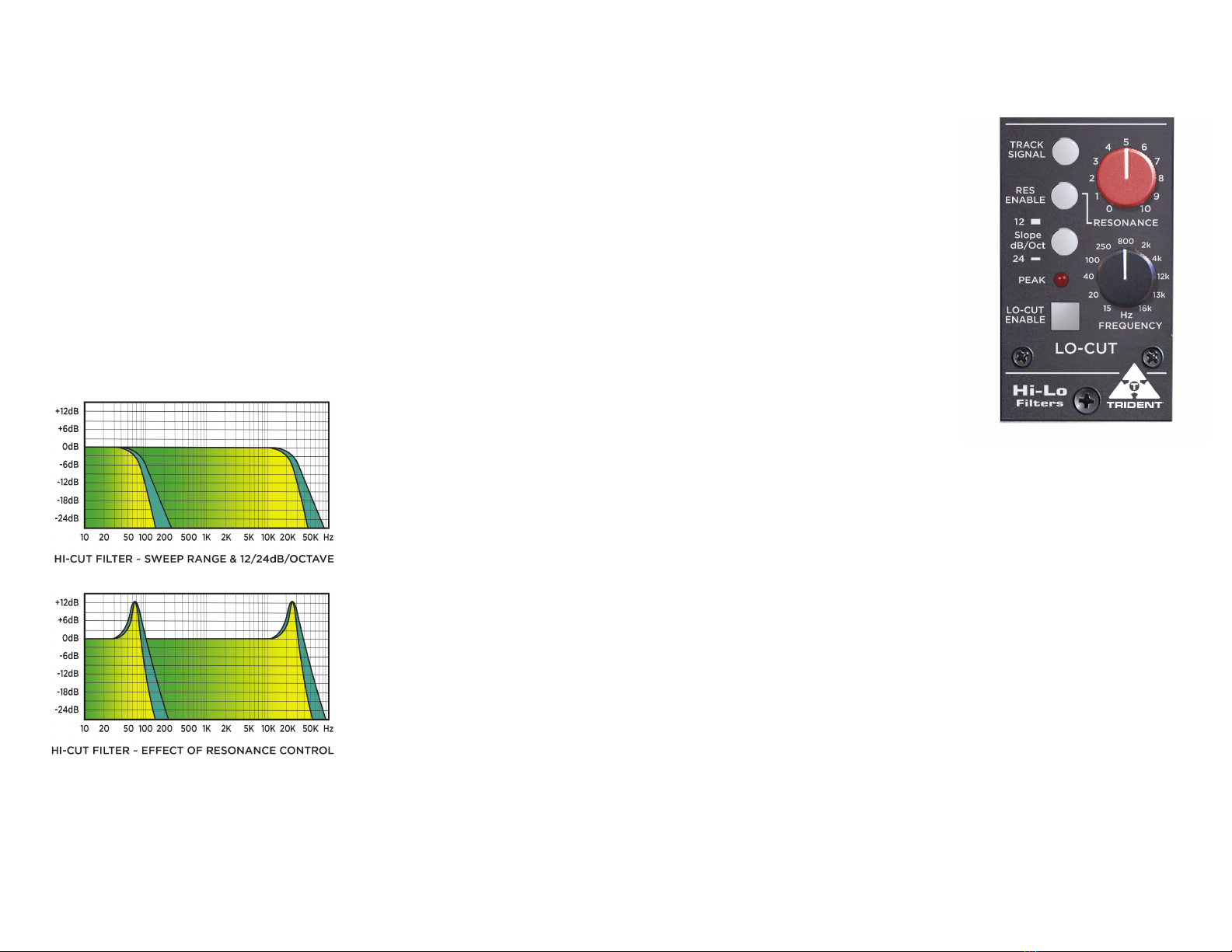
Further possibilities -
The sweep range of the Hi-Cut
filter is extremely wide, from
eectively subsonic, right up
to full audible bandwidth. This
suggests the possibility of fad-
ing tracks in and out, not in the
amplitude domain as is usual, but in the frequency domain.
Connecting two Hi-Lo filter modules in series, via an external linking system
such as on the Trident Deca Dent, permits filter slopes of up to 48dB per
octave to be realised(!).