Measurement Considerations
Maintenance
Operating Instructions
Trigger
•Laser and backlight function work
simultaneously when power is on
•Pull the trigger to turn the unit ON. When the
trigger is released it will show HOLD and the
reading will be held
Auto Power Off Function
•After 10 seconds, if the unit is unused, it will
power off automatically
Temperature Scale Selection
•Temperatures are displayed in ether Degrees
Celsius (°C) or Degrees Fahrenheit (°F)
•When the unit is turned on it is set to the
temperature scale last used
•To change the unit of measurement remove
the battery cap and slide switch to desired
scale
Operation
1. Remove the protective cap and push the
trigger. This will turn the unit ON
2. Point the sensor at the object to be
measured
3. Referring to the spot size figure, pull the
trigger and hold until a stable reading is
acquired
4. Replace the cap to extend the life and
protect the sensor
NOTE: Although the field of measurement/view
and the spot almost coincide, actually the field of
measurement corresponds to the diameter for 90%
optical response. The object to be measured needs
to be larger than the diameter (spot of size) by an
adequate margin of at least 2 x larger
Theory of Measurement
Every object emits infrared energy in accor-
dance with its temperature. By measur-
ing the amount of this radiant energy, it is
possible to determine the temperature of the
emitting object.
About Infrared
Infrared radiation is a form of light (electro-
magnetic radiation), and has the property
that it passes easily through air while it is
easily absorbed by solid matter. With an
emission thermometer which operates by
detecting infrared radiation accurate mea-
surement is possible, irrespective of the air
temperature or the measurement distance.
Emission Thermometer Structure
Infrared radiation which has been emitted
from the object is focused upon an infrared
radiation sensor, via an optical system.
This includes a lens which is transparent to
infrared radiation. And 5.3um cut off filter.
The output signal from the infrared radiation
sensor is input to an electronic circuit along
with the output signal from a standard
temperature sensor (Thermopile).
Emissivity
All objects emit invisible infrared energy.
The amount of energy emitted is propor-
tional to the object’s temperature and its
ability to emit IR energy. This ability, called
emissivity, is based upon the material that
the object is made of and its surface finish.
Emissivity values range from 0.10 for a very
reflective object to 1.00 for a black body.
Factory set emissivity value of 0.95, which
cover 90% of typical applications.
If the surface to the measured is covered
by frost or other material, clean it to expose
the surface.
If the surface to be measured is highly
reflective, apply masking tape or matt finish
black paint to the surface.
If the meter seems to be giving incorrect
readings check the front cone. There may
be condensation or debris obstructing the
sensor; clean per instructions in the main-
tenance section.
Thermal Emissivity
Substance Thermal Emissivity
Asphalt 0.90 to 0.98
Brick (red) 0.93-0.96
Cement 0.96
Ceramic 0.90-0.94
Charcoal 9powder) 0.96
Chrome Oxides 0.81
Cloth 0.98
Concrete 0.94
Copper Oxides 0.78
Earth 0.92-0.96
Glass 0.90-0.95
Human skin 0.98
Ice 0.96-0.98
Iron Oxides 0.78-0.82
Lacquer 0.80-0.95
Lacquer (matt) 0.97
Lather 0.75-0.80
Marble 0.94
Mortar 0.89-0.91
Paper 0.70-0.94
Plaster 0.80-0.90
Plastic 0.85-0.95
Rubber (black) 0.94
Sand 0.9
Snow 0.83
Textiles 0.9
Timber 0.9
Water 0.92-0.96
Battery Replacement
1. Power is supplied by a 9 volt “transistor”
battery. (NEDA 1604, IEC 6F22).
2. Remove the battery cover by gently sliding
it towards the bottom of the meter.
3. Remove and disconnect the old battery
from the meter and replace with a new
unit. Wind the excess lead length and put
the top of battery toward the lower side of
the battery chamber.
4. Replace the battery cover
5. When battery is installed, the meter
turns on automatically to check the
battery conditions. Power will turn off
automatically after 10 seconds without
operation.
Cleaning
• Periodically wipe the case with a damp cloth
and detergent, do not use abrasives or solvents.
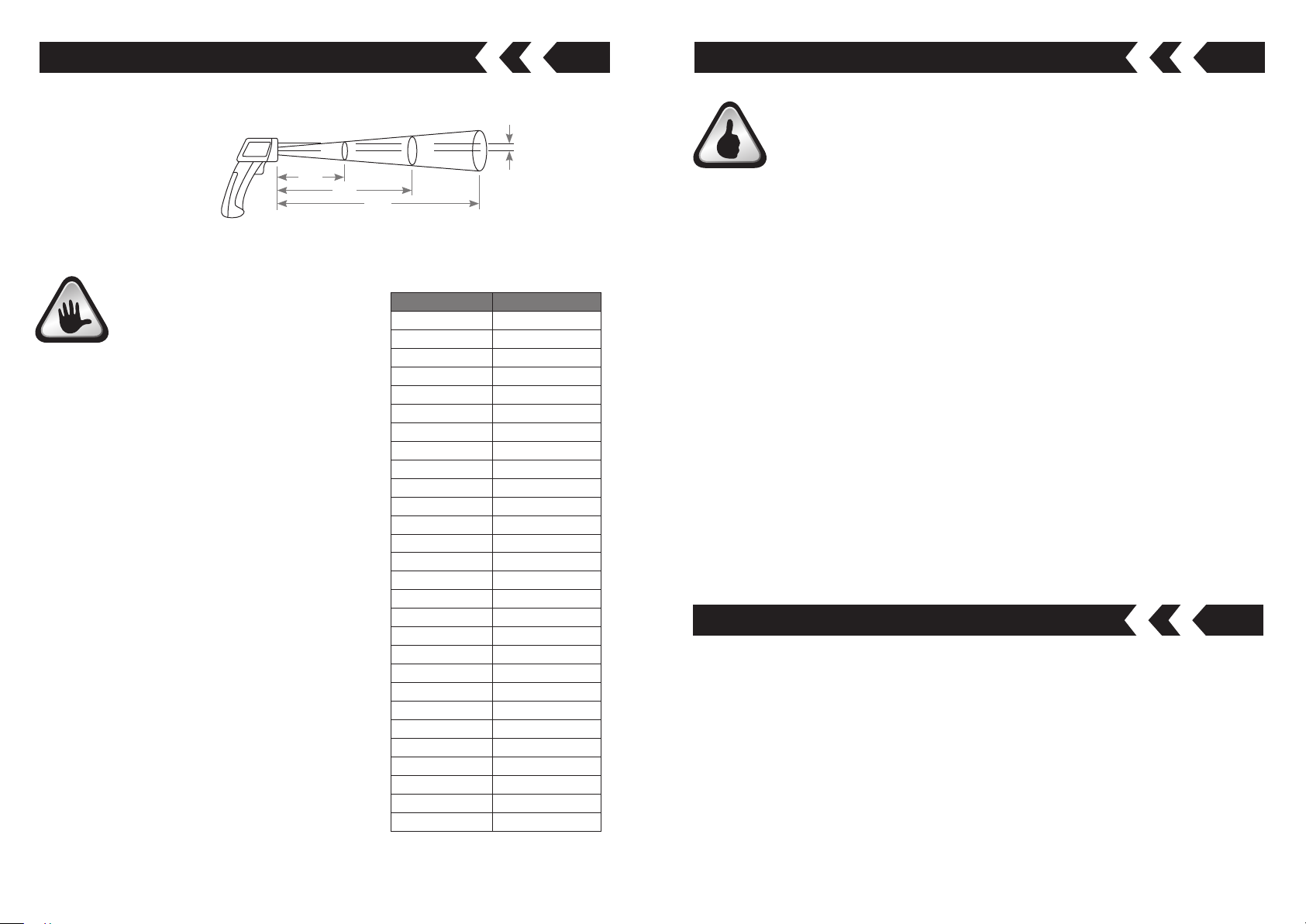
Spot size increases with distance from the probe tip as shown
250
25Ø 50Ø 100Ø
16
500
1000
Distance to object (mm)
Diameter of spot (mm)
Laser
Marker