Tridonic DALI MSensor 02 User manual

luxCONTROL
Product manual DALI MSensor 02


  Table of contents
- 3 / 38 -
Table of contents
Scope of documentation . . . . . . . . . . . . . . . . . . . . . . . . . . . . . . . . . . . . . . . . . . . . . . . . . . . . . . . . . . . . . . 4
Safety instructions . . . . . . . . . . . . . . . . . . . . . . . . . . . . . . . . . . . . . . . . . . . . . . . . . . . . . . . . . . . . . . . . . . 5
New features . . . . . . . . . . . . . . . . . . . . . . . . . . . . . . . . . . . . . . . . . . . . . . . . . . . . . . . . . . . . . . . . . . . . . . 6
Introduction . . . . . . . . . . . . . . . . . . . . . . . . . . . . . . . . . . . . . . . . . . . . . . . . . . . . . . . . . . . . . . . . . . . . . . . 7
Description . . . . . . . . . . . . . . . . . . . . . . . . . . . . . . . . . . . . . . . . . . . . . . . . . . . . . . . . . . . . . . . . . . . . . . . . 8
Installation . . . . . . . . . . . . . . . . . . . . . . . . . . . . . . . . . . . . . . . . . . . . . . . . . . . . . . . . . . . . . . . . . . . . . . . . 9
Commissioning and settings . . . . . . . . . . . . . . . . . . . . . . . . . . . . . . . . . . . . . . . . . . . . . . . . . . . . . . . . . . 10
Functions . . . . . . . . . . . . . . . . . . . . . . . . . . . . . . . . . . . . . . . . . . . . . . . . . . . . . . . . . . . . . . . . . . . . . . . . 12
Constant light control . . . . . . . . . . . . . . . . . . . . . . . . . . . . . . . . . . . . . . . . . . . . . . . . . . . . . . . . . . . . 12
Presence control . . . . . . . . . . . . . . . . . . . . . . . . . . . . . . . . . . . . . . . . . . . . . . . . . . . . . . . . . . . . . . . 17
Remote control . . . . . . . . . . . . . . . . . . . . . . . . . . . . . . . . . . . . . . . . . . . . . . . . . . . . . . . . . . . . . . . . . 21
Special DALI settings . . . . . . . . . . . . . . . . . . . . . . . . . . . . . . . . . . . . . . . . . . . . . . . . . . . . . . . . . . . . . . . 25
Enhanced functionality . . . . . . . . . . . . . . . . . . . . . . . . . . . . . . . . . . . . . . . . . . . . . . . . . . . . . . . . . . . . . . 29
Practical examples . . . . . . . . . . . . . . . . . . . . . . . . . . . . . . . . . . . . . . . . . . . . . . . . . . . . . . . . . . . . . . . . . 30
Individual office rooms . . . . . . . . . . . . . . . . . . . . . . . . . . . . . . . . . . . . . . . . . . . . . . . . . . . . . . . . . . . 30
Corridor . . . . . . . . . . . . . . . . . . . . . . . . . . . . . . . . . . . . . . . . . . . . . . . . . . . . . . . . . . . . . . . . . . . . . . 31
Neighbourhood function . . . . . . . . . . . . . . . . . . . . . . . . . . . . . . . . . . . . . . . . . . . . . . . . . . . . . . . . . . 32
Disposal . . . . . . . . . . . . . . . . . . . . . . . . . . . . . . . . . . . . . . . . . . . . . . . . . . . . . . . . . . . . . . . . . . . . . . . . . 33
Compliance . . . . . . . . . . . . . . . . . . . . . . . . . . . . . . . . . . . . . . . . . . . . . . . . . . . . . . . . . . . . . . . . . . . . . . 34
Reference list . . . . . . . . . . . . . . . . . . . . . . . . . . . . . . . . . . . . . . . . . . . . . . . . . . . . . . . . . . . . . . . . . . . . . 35
Appendix . . . . . . . . . . . . . . . . . . . . . . . . . . . . . . . . . . . . . . . . . . . . . . . . . . . . . . . . . . . . . . . . . . . . . . . . . 36
Commands for broadcast and luminaire groups . . . . . . . . . . . . . . . . . . . . . . . . . . . . . . . . . . . . . . . . 36
Commands to DALI address . . . . . . . . . . . . . . . . . . . . . . . . . . . . . . . . . . . . . . . . . . . . . . . . . . . . . . 37
  Scope of documentation
Documentation DALI MSensor 02 | 02-2012 | en - 4 / 38 -
Validity
These operating instructions are valid for the DALI MSensor 02. For better distinction from previous versions the DALI
MSensor 02 carries imprints with the information "Version 02" or "Firmware version V2.00".
Notice
The DALI MSensor 02 behaves differently to previous versions (V1.5 and earlier). The DALI MSensor is
therefore only backward compatible to a limited extent.
Please pay attention to notes in the individual chapters!
For version V1.5 or earlier sensors: pay attention to the notes in the respective documentation!
The DALI MSensor 02 is configured in the masterCONFIGURATOR software (V2.02. or later). Using older
versions of the software to configure the DALI MSensor 02 will result in incorrect operation.
Please make sure you are using an up-to-date version of the masterCONFIGURATOR software.
TRIDONIC GmbH & Co KG is constantly striving to develop all its products. This means that there may be changes in form,
equipment and technology.
Claims cannot therefore be made on the basis of information, diagrams or descriptions in these instructions.
The latest version of these operating instructions is available on our home page at
http://www.tridonic.com/com/en/operating-instructions.asp
Version information
Editorial deadline: 24-02-2012 Version number: 1.0 Issue date: 24-02-2012
Copyright
This documentation may not be changed, expanded, copied or passed to third parties without the prior written agreement of
TRIDONIC GmbH & Co KG.
We are always open to comments, corrections and requests. Please send them to .[email protected]
Imprint
Tridonic GmbH & Co KG
Färbergasse 15
6851 Dornbirn
Austria
T +43 5572 395-0
F +43 5572 20176
www.tridonic.com
...

  Safety instructions
Documentation DALI MSensor 02 | 02-2012 | en - 5 / 38 -
Safety instructions
The instructions in this section have been compiled to ensure that operators and users of the DALI MSensor 02 from Tridonic
are able to detect potential risks in good time and take the necessary preventative measures.
The operator must ensure that all users fully understand these instructions and adhere to them. This device may only be
installed and configured by suitably qualified personnel.
Intended use
Proper use
Steuergerät für den Betrieb DALI-fähiger Leuchten. The device may only be used for this intended purpose.
Improper use
Outdoor use. Extensions and modifications to the product.
Warning!
Improper use could result in injury, malfunction or damage to property.
The operator must inform all usersof the potential risks associated with the use of the equipment and of
protective countermeasures.
Dangers associated with the operation of the system
Danger!
Danger of electrocution
Disconnect the power to the entire lighting system before working on the lighting system!
Caution!
Risk of damage caused by condensation
Prior to commissioning the system, wait until the control device is at room temperature and completely dry!
Caution!
Risk of damage caused by humidity
Only use the control device in dry rooms and protect it against humidity!
Caution!
Electromagnetic compatibility (EMC)
Although the Tridonic control device meets the stringent requirements of the appropriate directives and
standards on electromagnetic compatibility, it could potentially interfere with other devices under certain
circumstances!
...

  New features
Documentation DALI MSensor 02 | 02-2012 | en - 6 / 38 -
New features
New grouping concept
The DALI MSensor 02 only assigns one DALI group, the luminaire group. The notion of a sensor group has been omitted
from the new group concept. This has resulted in changed behaviour in response to some DALI commands (see chapter
"Special DALI settings", page 25).
Reaction of DALI MSensor 02 to scene recalls
The way that the DALI MSensor 02 responds to scene recalls can be set. For example, it is possible to activate light control
by the DALI MSensor 02 by calling up a scene ( ).see chapter "Special DALI settings", page 25
Presence synchronisation with other DALI MSensor 02 groups
The DALI MSensor 02 makes it possible to set up presence synchronsiation between several DALI MSensor 02 groups. In
doing so, it is possible to specify how the DALI MSensor 02 should respond to any presence in other groups (see chapter
"Presence control", page 17
Extended operating modes for integration in other control
systems
Two new operating modes which are specially optimised to support integration into non-Tridonic control systems have been
built into the DALI MSensor 02 ( ).see chapter "Enhanced functionality", page 29
...

  Introduction
Documentation DALI MSensor 02 | 02-2012 | en - 7 / 38 -
Introduction
The DALI MSensor 02 is used in the comfortDIM system in Direct master mode. In this mode the sensor controls a DALI
group directly. Besides Direct master mode, the DALI MSensor 02 also supports two further modes for use in combination
with a higher-level DALI master controller:
Indirect master mode
Slave mode
The following chapters deal with Direct master mode in detail. Later on, ( ) thesee chapter "Enhanced functionality", page 29
other two modes are dealt with briefly.
...

  Description
Documentation DALI MSensor 02 | 02-2012 | en - 8 / 38 -
Description
The DALI MSensor 02 is a digital controller in the comfortDIM product range that can be used to control the control gear of a
DALI group collectively. The sensor combines three functions in one control device:
Constant light control
Presence-based control
Remote control
The DALI MSensor 02 is is available in four different housing designs:
Fitted in luminaire Recessed into ceiling
Surface-mounted Box-mounted
The DALI MSensor 02 is designed for the following principal applications:
Individual offices
Open-plan offices
Training/presentation rooms
Corridors, passageways and garages
The DALI MSensor 02 either controls all the units on the DALI circuit or a DALI group. The DALI MSensor 02 is Multi-master
compatible, i.e. it can be used in conjunction with other DALI controllers in the comfortDIM product range. This allows the
DALI MSensor 02 to be addressed and grouped in the same way as DALI control gear and makes it easy to configure the
system.The DALI MSensors 02 is configured in the masterCONFIGURATOR software (V2.02. or later).
...

  Installation
Documentation DALI MSensor 02 | 02-2012 | en - 9 / 38 -
Installation
The DALI MSensor 02 is connected directly to the DALI circuit and does not require its own power supply. It can be
connected to the DALI circuit without bothering about polarity. Power is supplied via the DALI circuit. The sensor draws 6 mA.
Notice
A maximum of 12 DALI MSensors 02 can be operated on a single DALI circuit. If more sensors are
connected, the increased data traffic this causes has an adverse affect on the light control function.
...
  Commissioning and Adaptions
Documentation DALI MSensor 02 | 02-2012 | en - 10 / 38 -
Commissioning and settings
The DALI MSensor 02 either controls all the devices on the DALI circuit or a DALI group. To enlarge the presence detection
area, it is possible to assign the same destination to several DALI MSensors 02. To achieve this, simply assign the sensors
to the same DALI group.
The DALI MSensor 02 is configured in the masterCONFIGURATOR software (V2.02. or later). The DALI MSensor 02 can be
assigned to a specific effective range. In addition, the parameters of the individual functions can be individually adjusted (see
).There are two ways of obtaining assignment to an effective range:chapter "Functions", page 12
Group assignment by using rotary switch
Group assignment by using masterCONFIGURATOR software
Notice
Luminaires must not belong to more than one DALI group! Otherwise the sensors will not interpret commands
sent to the luminaire correctly.
Unlike other DALI controllers, a DALI address is assigned to the DALI MSensor 02 during addressing. This
reduces the total number of available DALI addresses. This must be taken into account when designing the
DALI circuit!
Extending an existing DALI circuit
The DALI MSensor 02 can be used in an existing DALI circuit when a system is extended if the DALI
MSensor 02 controls its own group.It is not possible to operate a DALI MSensor 02 and a DALI MSensor
(V1.5 or earlier) in the same DALI group. Because of the modified grouping concept, there is no
synchronisation of constant light control and presence detection between the two equipment generations.
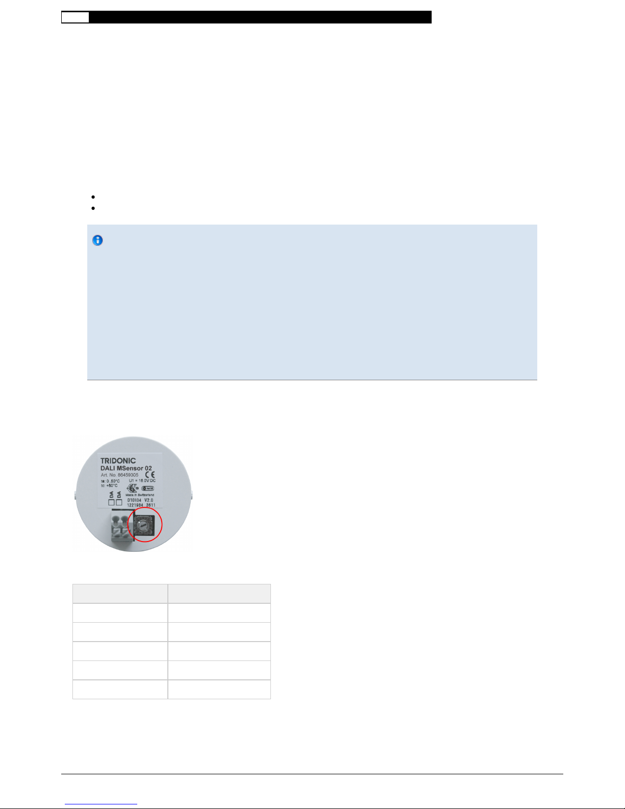
Group assignment by using rotary switch
The effective range of the DALI MSensor 02 is set using the rotary switch at the rear of the sensor. All control gear located
within the previously set effective range is controlled by the sensor.
Rotary switch setting Effective range (group)
0 All (broadcast)
1 0
2 1
3...9 2...8
A...F 9...14

  Commissioning and Adaptions
Documentation DALI MSensor 02 | 02-2012 | en - 11 / 38 -
Group assignment by using masterCONFIGURATOR
The effective range of the DALI MSensor 02 can be set in the masterCONFIGURATOR software (V2.02 or later). When this
assignment method is used, the position of the sensor's rotary switch is ignored and the assignment selected in the
masterCONFIGURATOR software is active. If the group assignment in the masterCONFIGURATOR software is cancelled,
the assignment set using the rotary switch becomes effective.
Replacing a faulty DALI MSensor (V1.5 or earlier)
It is only possible to replace a faulty DALI MSensor (V1.5 or earlier) by a DALI MSensor 02 if specific preconditions are met:
Make sure that there is no other DALI MSensor (V1.5 or earlier) in the DALI group in question!
Make sure that the faulty DALI MSensor (V1.5 or earlier) is not influenced by other DALI controllers (e.g. by the fact
that a DALI GC activates daylight-based control via the sensor group).
Further adaptation is required in the case other applications:
If you have any queries, please contact Tridonic Technical Support.
Alternatively, it is possible to use the masterCONFIGURATOR software to install the V1.5 firmware in the DALI
MSensor 02. The DALI MSensor 02 will then behave in the same way as previous-generation DALI MSensors.
...

  Functions
Documentation DALI MSensor 02 | 02-2012 | en - 12 / 38 -
Functions
The DALI MSensor 02 has the following functions and user interfaces:
Constant light control by means of ambient light sensor
Presence-based control by means of PIR motion sensor or presence detector
Remote control via an infrared input for two different IR remote controls
Constant light control
Description
Constant light control makes it possible to match the lighting in a room to the naturally available ambient light. To do this, the
ambient light sensor monitors the illuminance in the room, compares it to the previously set brightness setpoint and dims the
light until the received illuminance matches the desired setpoint. If several DALI MSensors 02 are used in the same luminaire
group, the light is dimmed until the light value is no longer less than the setpoint at every sensor.
Where ambient light values are high, this can result in ambient light-based bright-out and bright-in. If the measured
illuminance exceeds a specified threshold value for a period of time that is longer than the specified delay time, the luminaire
group is switched off by the DALI MSensor 02. This also applies in cases where motion is detected in the room. The
luminaire group is switched on again as soon as the measured illuminance falls below the brightness setpoint.
The Constant light control function ensures that the illuminance in the room remains constant and changes due to variable
amounts of ambient light in the room are compensated for. This produces greater comfort, illumination is always properly
adjusted, and it also saves energy.
Detection area of the ambient light sensor
The detection area of the sensor is sized so that a relatively large area, rather than just an individual location on the task
area, is covered and assessed. This ensures that objects being moved around cannot cause incorrect measurements.
  Constant light control
Documentation DALI MSensor 02 | 02-2012 | en - 13 / 38 -
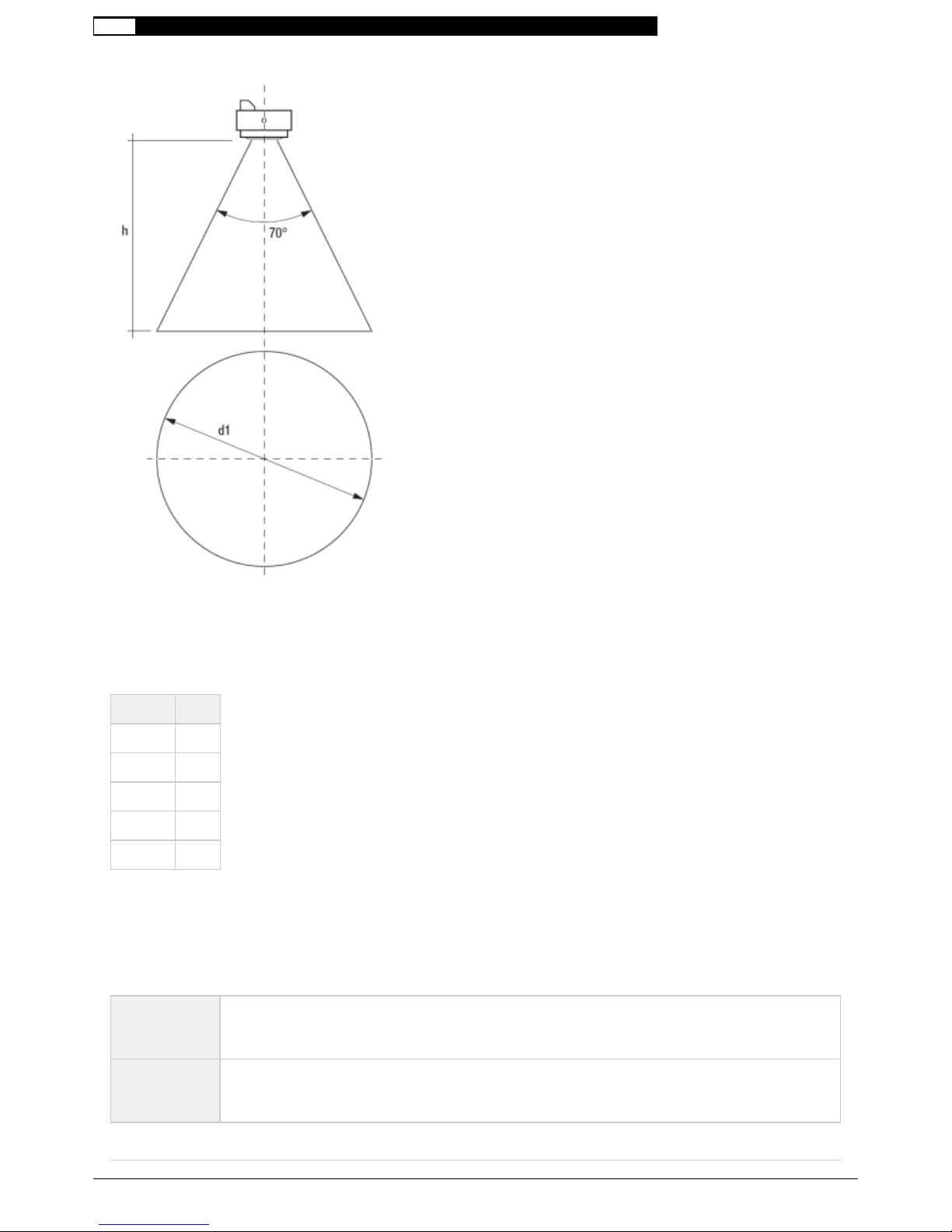
The diameter of the detection area depends on the detection angle of the sensor and the height at which it is mounted.
Calculating the diameter:
d1 = 2 × tan(0.5 × 70°) × h
Typical example values of detection area:
Height h Ø d1
2.0 m 2.8 m
2.5 m 3.5 m
3.0 m 4.2 m
3.5 m 4.9 m
4.0 m 5.6 m
Operating modes
The ambient light sensor has three operating modes. Constant light control can be activated or deactivated. Constant light
control can also be deactivated temporarily.
Ambient light
control:
"enabled"
Light control of the luminaire group is activated by triggering the DALI MSensor 02.
Ambient light
control:
"disabled"
The light control of the DALI MSensor 02 is permanently deactivated. A fixed setpoint in the luminaire
group is invoked by triggering the DALI MSensor 02.

  Constant light control
Documentation DALI MSensor 02 | 02-2012 | en - 14 / 38 -
Ambient light
control:
"temporarily
disabled"
Light control can be temporarily deactivated by a manual intervention on another DALI controller. Doing
so temporarily switches off light control. The luminaires remain adjusted to the corresponding setpoint.
Light control is reactivated at the next switch-on or by an activation command.
Commissioning
Setting operating modes
The individual operating modes can be set by using the masterCONFIGURATOR software (V2.02 or later) (see chapter
"Source directory", page 35
Setting the brightness setpoint
The brightness setpoint is set by using an IR SMART Controller, DALI RC or masterCONFIGURATOR.
Notice
The factory settings of the ambient light sensor are appropriate for normal conditions in a typical office room.
Factors such as the room height, type of furniture and nature of the floor can make it necessary to make
adjustments.
Check that ambient light control adjusts the lighting to desired levels.
In case of incorrect operation or unsatisfactory results: adjust the brightness setpoint.
Notice
A suitable brightness setpoint is typically defined by using a lux meter to make a localised brightness
measurement. The results obtained may vary depending where the measurement is made and what the
external lighting conditions are.
Check ambient light control at various locations within the measuring area and under varying external
lighting conditions.
Make sure that the selected brightness setpoint takes into account varying conditions.
Procedure with IR SMART Controller
For the names of the buttons with letters, see the figure showing the IR SMART Controller (see chapter "IR SMART
)Controller", page 21
Set the desired brightness by pressing the Up/Down button (F and G)
Save the new brightness setpoint by pressing the SET button (C)
-› DALI MSensor 02 briefly dims the luminaire group up and down
Procedure with DALI-RC
For the names of the buttons with letters, see the figure showing the DALI RC ( )see chapter "DALI RC", page 22
Set the desired brightness by pressing the +/- button (J)
Save the new brightness setpoint by pressing the AUTOMATIC button (K) for at least 3 seconds.
-› DALI MSensor 02 briefly dims the luminaire group up and down
  Constant light control
Documentation DALI MSensor 02 | 02-2012 | en - 15 / 38 -
Procedure with masterCONFIGURATOR
Directly enter the brightness setpoint
Setting the ambient light-based bright-out and bright-in
This function can be activated or deactivated. The individual parameters can be adjusted. All settings can be made by using
the masterCONFIGURATOR software (V2.02 or later) ( ).see chapter "Source directory", page 35
Tricks and hints
Position the ambient light sensor correctly
Ambient light control is based on measuring reflected artificial light and daylight. This light must be detected correctly and
completely. Prevent measurements being falsified by other light sources. Positioning the ambient light sensor correctly is
crucial:
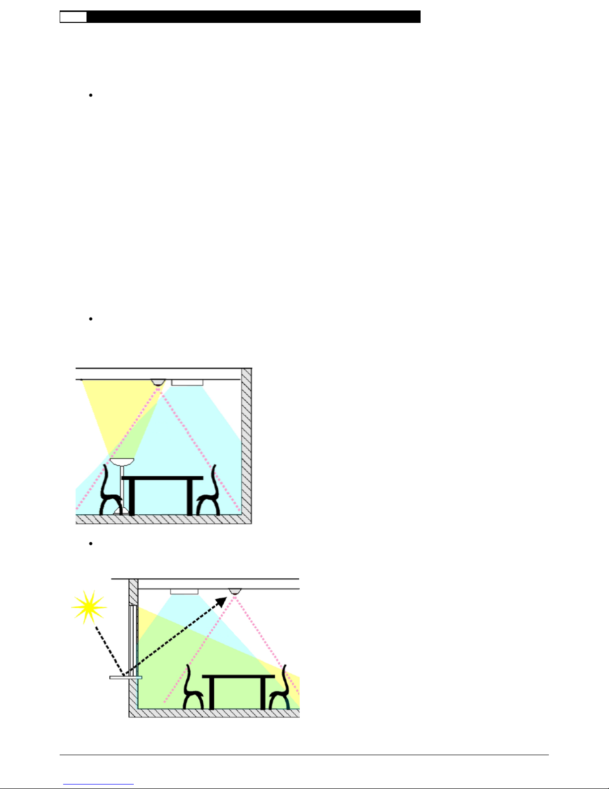
1. In order to be able to control ambient lighting properly, the sensor must be able to detect the light from the controlled
luminaires completely.
Position the sensor so that the sensor's detection area lies within the area that is lit by the controlled luminaires.
2. If the sensor is directly exposed to other light sources, this falsifies the results obtained and the reflected artificial light and
daylight can no longer be detected correctly.
Position the sensor so that it is not directly exposed to other artificial light sources (e.g. free-standing luminaires in the
room).

  Constant light control
Documentation DALI MSensor 02 | 02-2012 | en - 16 / 38 -
Position the sensor so that it is not directly exposed to sunlight:
Make sure that the detection area of the sensor lies within the room.
Make sure that the sensor is far enough away from any window area.
Make sure that any glare or sunlight reflected by shiny glass or metal surfaces cannot hit the sensor.
3. If more than one sensor is being used in a room it is possible that the detection areas of the sensors may overlap.
Overlapping detection areas may cause the different control circuits to affect one another and this may lead to false results.
Position the sensors so that their detection areas do not overlap.
...
  Presence control
Documentation DALI MSensor 02 | 02-2012 | en - 17 / 38 -
Presence control
Description
Presence-based control makes it possible to link illuminance to the presence or absence of people. The light is switched on
as soon as a person enters a room. When the person leaves, the light is set to a predefined light value after a certain time
lapse. Presence-based control offers the benefits of saving energy as well as the convenience of automatic lighting control.
The device has different operating modes and profiles that can be adjusted in the masterCONFIGURATOR software (V2.02
or later).
Notice
The presence-based control of the DALI MSensor 02 reacts to moving thermal radiation from people. Other
heat sources (e.g. photocopiers, radiators, etc.) may have an adverse affect on presence-based control.
Make sure that there are no other heat sources in the immediate vicinity of the sensor.
Detection area of the motion sensor
The detection area of the motion sensor consists of a pattern of various measurement fields. The following conditions must
be met in order for an object to be detected reliably:
The object must move from one measurement field to another
The temperature of the object must be different from the background temperature
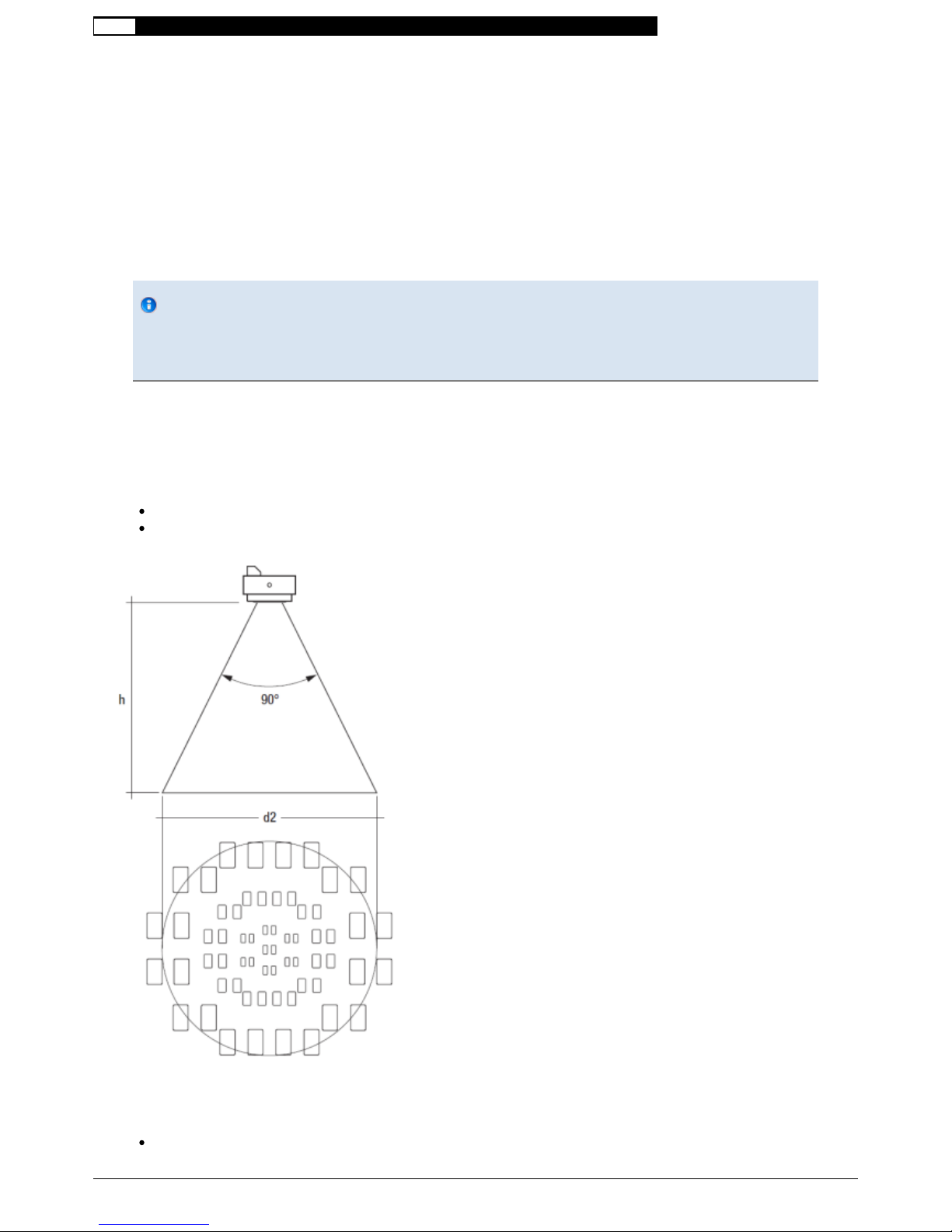
The diameter of the detection area depends on the detection angle of the sensor and the height at which it is mounted. The
mounting height also has an effect on the sensor's accuracy.
The position and mounting height produce two different detection areas:
in the centre of the detection area, the sensor operates as a presence detector, i.e. objects are detected merely by

  Presence control
Documentation DALI MSensor 02 | 02-2012 | en - 18 / 38 -
arm movements, etc. and do not need to move through the room. (This applies up to a maximum height of 3 m)
Throughout the entire detection area, the sensor operates as a motion sensor, i.e. objects are detected when they
move through the room
Calculating the diameter:
d2 = 2 × tan(0.5 × 90°) × h
Typical example values of detection area:
Height h Ø d2
2.0 m 4 m
2.5 m 5 m
3.0 m 6 m
3.5 m 7 m
4.0 m 8 m
Notice
The recommended maximum room height is 3 m for office applications and 4 m for corridor applications.
For presence detection, it is vital that arm movements, etc. can be detected.Position the sensor on the ceiling
so that the room user's hands are located in the centre of the detection area and are not concealed by
display screens, backs, etc.
Operating modes
The motion sensor has four different operating modes.
Operating
mode:
"enabled"
The light is switched on or off automatically in response to the presence of a person.
Operating
mode:
"enabled
(only OFF)"
The sensor switches off if there is no motion detected in the detection area, but does not switch on again
even if motion is detected. Switch-on must be obtained through a manual switch-on command (e.g. using
DALI RC). The manual switch-on command (e.g. scene recall) must either be directed at the luminaire group
or to all devices (broadcast) in order for presence-based control to be activated. The DALI MSensor 02
ignores switch-on commands sent to other groups.
Operating
mode:
"disabled"
The motion sensor is deactivated. The light must be switched on and off manually.
Operating
mode:
"Never-Off"
After no motion has been detected and the delay time has elapsed, the sensor dims to a low light value
(absence value) but does not switch off.
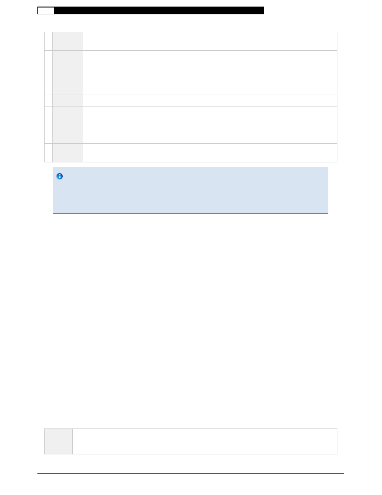
Profiles
  Presence control
Documentation DALI MSensor 02 | 02-2012 | en - 19 / 38 -
1Fade-in
time The time needed to reach the presence value.
APresence
value The value that the luminaire group assumes while a person is present in the room.
2run-on
time The time that starts to run after the last motion is detected in a room and after which, when it elapses, the
fade-down time is started. If another movement is detected in the room during the delay time, the delay
time is restarted.
3Fade time Time in which the lighting is faded down to the absence value.
4Switch-off
delay The time for which the absence value is maintained if no motion is detected.
BAbsence
value The value that the luminaire group assumes during the switch-off delay.
5Fade-off
time The time needed to dim down from the absence value.
Notice
If the motion sensor is switched off manually during operation, it is temporarily deactivated. The duration of
deactivation depends on the value of the "Dead time (manual OFF)" parameter. If the sensor detects motion
during the time lag, it restarts the time lag afresh. The motion sensor is reactivated when the time lag has
elapsed.
Commissioning
Setting the operating mode
The individual operating modes can be set in the masterCONFIGURATOR software (V2.02 or later) (see chapter "Source
).directory", page 35
Setting the profile
The individual profiles can be set in the masterCONFIGURATOR software (V2.02 or later) (see chapter "Source directory",
).page 35
Setting the "Dead time (manual OFF)"
The value of "Dead time (manual OFF)" can be set in the masterCONFIGURATOR software (V2.02 or later) (see chapter
"Source directory", page 35
Enhanced functionality
DALI MSensors 02 of different DALI groups can synchronise their motion detection, i.e. a DALI MSensor 02 can monitor
other DALI groups with DALI MSensors 02 and respond appropriately to the "Motion detected" synchronisation command in
another group. A DALI MSensor 02 can monitor up to 4 other DALI groups.
The following parameters can be adjusted:
Go to
Presence
value
The "Motion detected" synchronisation command is interpreted in the same way as if the actual sensor
detected motion.

  Presence control
Documentation DALI MSensor 02 | 02-2012 | en - 20 / 38 -
Go to
Absence
value
The "Motion detected" synchronisation command causes the DALI MSensor 02 to maintain the absence value.
If the sensor is already at the absence value, it keeps resetting the switch-off delay and remains at that value. If
the sensor is in the "OFF" state, it switches to the absence value. If the sensor is at the absence value, the
synchronisation command is ignored.
MASK The DALI MSensor 02 ignores the "Motion detected" synchronisation command of the other group (factory
setting).
Notice
In the operating mode: "enabled (only OFF)", the DALI MSensor 02 does not send synchronisation
commands until the sensor has been activated by a manual switch-on command.
In the operating mode: "enabled (only OFF)", the DALI MSensor 02 does not respond to synchronisation
commands until the sensor has been activated by a manual switch-on command.
...
Table of contents
Other Tridonic Accessories manuals


