Eminent ET-II User manual

FLUID DYNAMIC DAMPING FOR THE ET-II
EMINENT TECHNOLOGY, INC.
225 EAST PALMER STREET
TALLAHASSEE, FL 32301
(850) 575-5655

INTRODUCTION
This kit includes a properly engineered fluid dynamic trough for the ET-2 Tonearm, which
will operate on any turntable without interfering with any feature or adjustment ability of the
tonearm. Installation is simple and straightforward, and does not require tonearm removal from
the turntable or any special tools.
Be very careful when handling the silicone fluid, which is included with this kit. Be sure
not to get any on the air bearing portions of the tonearm. If you accidentally get the silicon fluid
on your hands, be sure they are clean before handling any part of the tonearm.

If you accidentally SPILL silicone fluid on the air bearing, do not operate the tonearm
until that part is thoroughly cleaned. First, clean the part with a household spray cleaner, (409,
Fantastic, Windex, etc.) using paper towels. Then use alcohol and paper towels, bath tissue, or
cotton balls rubbing the bearing thoroughly. Silicone fluid will not damage the bearing. The
inside portion of the manifold may have to be cleaned if the bearing is moved with silicone fluid
on its surface. Consult the ET-2 Owners Manual or the factory if you have any questions.

The silicone damping trough is carefully designed to and positioned so that it is unlikely
that fluid will get on your hands or any part of the tonearm during normal use.
The rigid semi circular trough is constructed of an anodized aluminum alloy. The shape
always maintains a constant distance between the paddle and any surface of the trough over the
full travel of the tonearm.

INSTALLATION
We recommend that the user not install the fluid damping trough until you become
thoroughly familiar with the use and features of the ET-2, and feel completely comfortable using
the tonearm. You should know how to level the tonearm and set the tracking force before
installing the damping trough.
We believe that the damping trough can be installed on any turntable/ET-2 combination
without any performance limitation. If you have specific questions about any installation, feel free
to contact us. The air pump should be turned off during installation.

During all of the installation procedures, put your cartridge stylus guard in place on the
cartridge and leave the cuing lever in the up position. No adjustments will be made to the cuing
assembly.


In order to install the kit you must first remove the counterweight assembly from the
backside of the air bearing spindle. This is done by loosening the top screw on the counterweight
clamp. Loosen this screw about one full turn and pull the clamp off of the end of the spindle. Do
not overtorque these screws when re-assembling this part. The 3/32” allen wrench which is
supplied with the ET-2 is the only tool required for installation.
After the counterweight clamp is removed from the air bearing spindle you must remove
the I-beam from the clamp. This is also done by removing the clamp cover screw and pulling
outward on the I-beam. The I-beam should pull out exposing a stainless steel fork spring on its
end.

The I-beam should then be re-installed in the new supplied counterweight clamp/paddle
assembly. Install the new clamp cover leaving the screw loose. Then slide the fork spring of the
I-beam under the clamp cover and tighten the screw.
Install the new counterweight clamp/I-beam assembly onto the spindle. Be careful with
the wires to make sure that they are not being pinched on the underside of the counterweight
clamp as it is being pushed onto the spindle. There is, by design a tight fit between the spindle
and the counterweight clamp. When the clamp is in place and pushed onto the spindle until it
stops, you can tighten the clamping screw. This screw should only be tightened until it offers a
slight resistance.

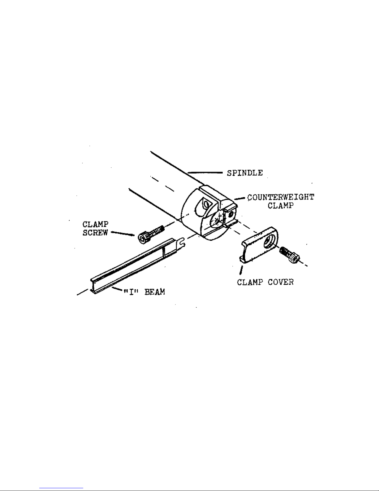
A very rigid coupling occurs with only a small amount of torque on this screw because of
the close tolerances. Overtorquing this screw can distort the air bearing spindle and crack the
counterweight clamp.
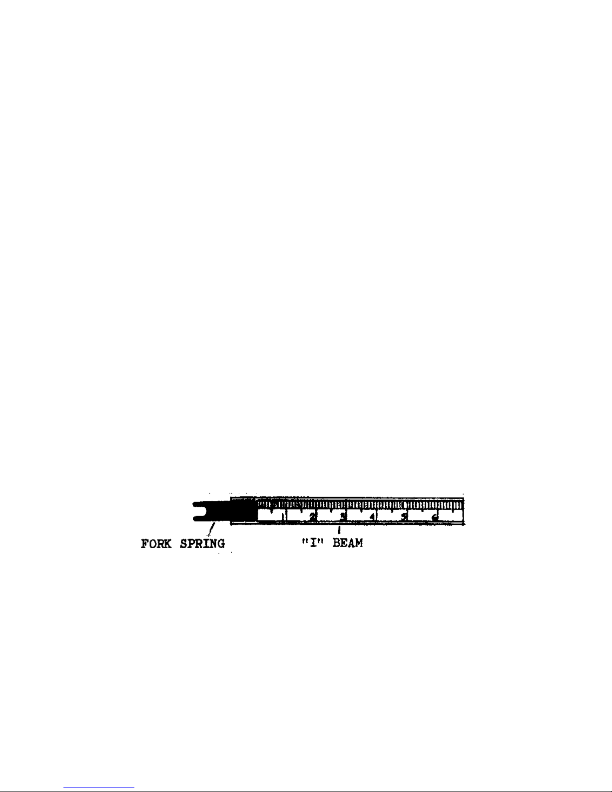
If the fork spring breaks off the I-beam during the above process it can be glued back into
place using ordinary “super glue” (cyanoacrolate) and then re-assembled.
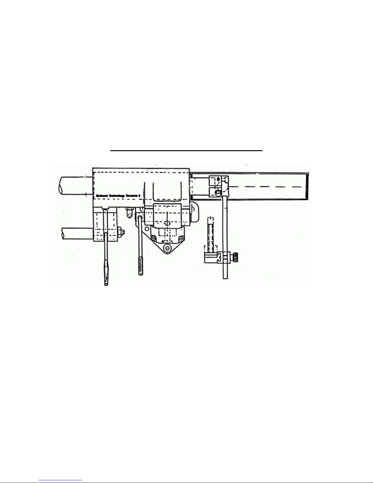
The counterweight I-beam should be positioned by rotating the counterweight clamp on
the spindle until the I-beam is parallel to the tonearm tube. It can be positioned up or down
slightly with respect to the tonearm tube, but generally parallel is the best position.
A very aggressive adhesive has been applied to the trough along the side, which is to be
attached to the underside of the manifold housing. When the wax paper is removed exposing the
adhesive on the trough it is ready to be put in place.

DAMPING TROUGH WITH ADHESIVE PADDLE


Study the drawings carefully and position the trough on the underside of the manifold
housing as shown. If the tonearm is viewed from above, the trough should be positioned directly
under the spindle and parallel to it. The inside fluid stop should be directly up against the
manifold housing. When the above two conditions are met, light finger pressure under the trough
will secure it to the manifold housing. It can be repositioned if necessary. Heavy finger pressure
clamping the trough to the manifold housing will almost permanently secure the trough to the
housing.


The paddle is threaded into the counterweight clamp and can be raised or lowered by
rotation. Turn the paddle until it is positioned about 1/16” above the dry trough across the full
travel of the tonearm. (It is OK to move the air bearing back and forth without the air pump
operating.)

ADDING FLUID
Enough fluid is supplied for several refills. Initially, about 1 cc of fluid should be
uniformly spread along the trough. An additional ½ cc of fluid may be required to establish contact
between the paddle and the fluid over the full travel of the spindle.
SETTING THE TRACKING FORCE AND LEVELING THE TONEARM
If the counterweights were not removed or repositioned along the I-beam, then the
tracking force should be the same and no adjustment is necessary. Fluid damping of a tonearm
does not affect the tracking force.

The additional mass of the damping trough adds about 18 grams to the mass of the
tonearm. This additional mass may affect a lightly suspended turntable so it is recommended that
the level be checked. Use the procedures described in the tonearm owner’s manual. Please note
that the tonearm now responds much more slowly due to fluid damping. YOU ARE NOW
READY TO ENJOY MUSIC AGAIN!

TECHNICAL DISCUSSION
The compliance (spring stiffness) of a phono cartridge and the effective mass of a tonearm
create a spring-mass system with a corresponding natural frequency. For a typical
tonearm/cartridge combination, the resonant frequency of this spring/mass system generally falls
below 20 Hz. On the surface it would seem that this does not create a problem. However, the
rise in frequency response of this system for most arm/cartridge combinations is quite substantial
(usually on the order of 8dB with a very high Q) and would not be tolerated in any other
associated piece of equipment (speakers, electronics, etc.) The effects that result from this rise in
response are in some cases subtle and in other cases substantial.

PHASE SHIFT
If a tonearm/cartridge system has a substantial rise in response below 20 Hz as most do,
the phase response at the low end will be shifted and phase shift will occur beginning at 2 to 3
times the resonant frequency down to Fr. The time in which low frequency signals come from the
tonearm will be shifted slightly with respect to mid-range frequencies within the audible range and
substantially shifted up to several periods at resonance. This is difficult to measure with a
tonearm, but easy to measure in a loudspeaker and the two responses are directly related. We
find it interesting that this as a tonearm performance parameter has never been discussed. We do
not know the audible effect of a purely phase shifted low frequency response. The ET-2 with the
damping trough will exhibit almost perfect low frequency phase response.

WOW AND FLUTTER
Wow and flutter, FM distortion and surface irregularities in the LP should all be grouped
together because, as we will see, they are all tied together.
When you cut a pure tone (say 1kHz) onto an LP and then play it back on a
turntable/tonearm/cartridge system, you would hopefully want 1kHz to come back. Something
close to 1kHz comes back, but rapidly being shifted up and down around 1kHz. If the frequency
is shifted up to 1001Hz and down to 999Hz within a short period of time, the amount of shift is
.1%. If the shift occurs less than 10 times a second, it is considered as flutter. The two measures
are generally lumped together and called wow and flutter.
Table of contents
Other Eminent Accessories manuals