Braun Aesculap OP930 Manual

Aesculap®
Aesculap Endoscopic Technology
Instructions for use/Technical description
Xenon Light Source OP930
Gebrauchsanweisung/Technische Beschreibung
Xenon-Lichtquelle OP930
Mode d’emploi/Description technique
Source de lumière froide au xénon OP930
Instrucciones de manejo/Descripción técnica
Fuente de luz de Xenon OP930
Istruzioni per l’uso/Descrizione tecnica
Fonte di luce allo xenon OP930
Instruções de utilização/Descrição técnica
Fonte de luz Xénon OP930
Gebruiksaanwijzing/Technische beschrijving
Xenon-lichtbron OP930
Bruksanvisning/Teknisk beskrivning
Xenon-ljuskälla OP930
Инструкция по примению/Техническое описание
Ксеноновый источник света OP930
Návod k použití/Technický popis
Xenonový světelný zdroj OP930
Instrukcja użytkowania/Opis techniczny
Ksenonowe źródło światła OP930
Návod na použivanie/Technický opis
Xenónový svetelný zdroj OP930
Kullanım Kılavuzu/Teknik açiklama
Xenon ışık kaynağı OP930


1 2 3 4 5 6
9
10
11
12
14
13
15
16
17
8 7

2
Aesculap®
Xenon Light Source OP930
Aesculap®
Xenon Light Source OP930
Legend
1Power OFF switch
2Power ON switch
3Power ON indicator
4Lamp OK indicator (while lamps are in operation)
5Brightness control
6Optical cable connection
7Device feet
8Change lamp indicator
9Xenon lamp
10 Light source connection
11 Optical cable
12 Instrument connection
13 Power socket
14 Power cord
15 Fuse holder
16 Equipotential connector
17 Fast-action locks
Symbols on product and packages
Caution
Follow instructions for use (small white man on a
blue background)
Type CF applied part
Optical cable connection
Potential equalization connector
Indicator: Lamp needs replacing
Indicator: Lamp within permissible operating period
Hazardous electrical voltage
Fuse
Alternating current
On/Off switch
Marking of electric and electronic devices according
to directive 2002/96/EC (WEEE), see Disposal

3
Contents
1. Safe handling 3
1.1 Safe for use in conformance with IEC regulations 4
1.2 Safety information regarding XBO reflector lamps 4
2. Product description 4
2.1 Scope of supply 4
2.2 Components required for operation 4
2.3 Intended use 4
2.4 Operating principle 5
3. Preparation and setup 5
3.1 First use 5
3.2 Presetting the correct voltage 5
4. Working with the xenon light source 6
4.1 System set-up 6
4.2 Function checks 7
4.3 Safe operation 7
5. Validated reprocessing procedure 7
5.1 General safety instructions 7
5.2 General information 8
5.3 Dismantling prior to carrying out the reprocessing procedure 8
5.4 Preparations at the place of use 8
5.5 Preparation before cleaning 8
5.6 Cleaning/disinfection 8
5.7 Wipe disinfection for electrical devices without sterilization 9
5.8 Inspection, maintenance and checks 9
6. Maintenance 9
6.1 Replacing xenon lamp 9
7. Troubleshooting list 11
7.1 Fuse replacement 12
8. Technical Service 12
9. Accessories/Spare parts 12
9.1 Optical cable accessories 12
9.2 Optical cable connection accessories 12
9.3 Accessories for power cord 12
9.4 Other accessories 12
9.5 Spare parts 12
10. Technical data 13
10.1 Ambient conditions 13
11. Disposal 13
1. Safe handling
►Transport the product only in its original box.
►Prior to use, check that the product is in good working order.
►Observe “Notes on Electromagnetic Compatibility (EMC)“, see
TA022130.
►To prevent damage caused by improper setup or operation, and in order
not to compromise warranty and manufacturer liability:
– Use the product only according to these instructions for use.
– Follow the safety and maintenance instructions.
– Only combine Aesculap products with each other.
– Adhere to application instructions according to relevant norms, see
Safe for use in conformance with IEC regulations.
►Inspect the accessories regularly: Electrode cables and endoscopic
accessories, in particular, must be checked for possible damage to the
insulation.
►Keep the instructions for use accessible for the user.
►Always adhere to applicable standards.
►Ensure that the electrical facilities in the room in which the device is
being used conform to IEC norms.
►Unplug the device by pulling on the plug, and never on the power cord.
►Do not use xenon light sources in areas where there is a risk of explo-
sion.
WARNING
Risk of injury to patients due to inappropriate
application!
►The product and accessories should only be
operated by qualified or trained and experi-
enced personnel.

4
Aesculap®
Xenon Light Source OP930
1.1 Safe for use in conformance with IEC regulations
Operating environment
►Do not use the xenon light source at more than 2500 m above sea level.
►Make certain that the ambient temperature does not exceed 35 °C.
►Make certain that the device’s ventilation ducts are not covered.
►Make certain that the following minimum distances from other devices
are maintained:
– on the sides 50 mm
–fromtherear60mm
►Make certain that only non-conductive optical cables are used. This
applies in particular to products from other manufacturers, in order to
meet CF requirements.
►To avoid failure of the xenon lamp during an operation: Make certain
that the xenon lamp is replaced after 500 hours of operation (i.e., its
guaranteed service life). Check the operating time counter.
1.2 Safety information regarding XBO reflector lamps
►Make certain that xenon lamps are operated only with enclosed xenon
light sources.
►Only operate XBO lamps with the safety cladding and protecting cap.
►When performing maintenance or repairs, always wear protective garb
(safety glasses and gloves).
►When doing maintenance or repair work, make certain that the reflec-
tor opening is not pointing towards any persons.
2. Product description
2.1 Scope of supply
Note
The xenon light source OP930 does not have a spare lamp. As the xenon
lamp may fail before the guaranteed operating period has elapsed, always
have a spare lamp available, see Accessories/Spare parts.
2.2 Components required for operation
2.3 Intended use
The xenon light source OP930 is used to illuminate the operative field and
body cavities during medical applications.
DANGER
Risk of fatal injury from electric shock!
►Do not open the product.
►Connect the product only to a grounded power
supply.
WARNING
Risk of injury from explosion!
►Exercise caution when working with the xenon
lamp. The permissible inner pressure of the
xenon lamp when cold is ca. 20 bar.
►Do not use the xenon lamp more than 1.25
times longer than its average service life. During
operation, the inner pressure of the lamp
increases threefold.
WARNING
Risk of injury to eyes from strong ultraviolet radi-
ation and high luminance!
►Do not look directly into or at the xenon lamp.
Art. no. Designation
OP930 Xenon light source
OP935 Aesculap-Storz optical cable connection
TA009789 Instructions for use for Xenon Light Source OP930
TA022130 Notes on electromagnetic compatibility (EMC)
Art. no. Designation
OP930 Xenon light source
TE730 to TE780 Power cord
OP906
OP913
OP914
Optical cable

5
2.4 Operating principle
When the device is switched on, a xenon lamp is ignited. The xenon lamp
is operated under output control.
The xenon lamp generates free-burning discharge arcs between two elec-
trodes in pure xenon gas. The small gap between the electrodes allows for
creation of a source of illumination closely resembling that of a spotlight.
The light is filtered through the cold light reflector, propagated through
the optical cable and directed to the field of view (operative field).
Monitoring the operating time of the xenon lamps
The xenon light source OP930 is fitted with an operating time counter that
registers the number of hours the lamp has been in operation. During
operation, the xenon lamp OK display 4is illuminated. If a lamp operating
period of 500 hours is exceeded, the change lamp indicator 8comes on.
Monitoring temperature
In order to safeguard the xenon light source against overheating, the
operating temperature of the power supply unit and xenon lamp are con-
tinuously monitored. If the limiting temperature is exceeded, the xenon
lamp switches off. The fan is activated during the cooling phase. The
xenon light source can be used again after a brief period.
Brightness control
The desired brightness can be continuously adjusted with the brightness
control 5.
3. Preparation and setup
Non-compliance with the following instructions will preclude all respon-
sibility and liability in this respect on the part of Aesculap.
►When setting up and operating the product, adhere to
– national regulations for installation and operation,
– national regulations on fire and explosion protection.
Note
For the safety of patients and users it is essential that the mains power cord
and, especially, the protective earth connection are intact. In many cases
defective or missing protective earth connections are not registered imme-
diately.
►Connect the device via the potential equalization terminal at the rear
panel of the device to the potential equalization system of the room
used for medical purposes.
Note
The potential equalization lead can be ordered from the manufacturer as
art. no. GK535 (4 m length) or TA008205 (0.8 m length).
3.1 First use
3.2 Presetting the correct voltage
The mains voltage must correspond to the voltage indicated on the type
plate at the back of the unit.
DANGER
Danger of explosion from a device that is improp-
erly set up!
►Do not use the device in explosion-hazard areas.
►Make certain that the power plug is connected
to the power supply outside of any areas where
there is a risk of explosion.
WARNING
Risk of injury and/or product malfunction due to
incorrect operation of the electromedical system!
►Adhere to the instructions for use of any medi-
cal device.

6
Aesculap®
Xenon Light Source OP930
4. Working with the xenon light source
4.1 System set-up
►Set up the device on an even surface in a non-sterile area.
►Make certain that the device support (e.g., table, hanging ceiling light,
medical cart or similar) is sufficiently stable.
►Make certain that the device is safeguarded against vibration during
operation.
Connecting the accessories
Combinations of accessories that are not mentioned in the present
instructions for use may only be employed if they are specifically intended
for the respective application, and if they do not compromise the perfor-
mance and safety characteristics of the products.
Also note that any equipment connected at the interfaces must demon-
strably meet the respective IEC standards (e.g. IEC 60950 for data process-
ing equipment, IEC/DIN EN 60601-1 for electromedical devices).
All configurations must comply with basic standard IEC/DIN EN 60601-1.
Any individual connecting devices with one another is responsible for such
configuration and must ensure compliance with basic standard IEC/DIN
EN 60601-1 or applicable national standards.
►Please address your B. Braun/Aesculap partner or Aesculap Technical
Service with any inquiries in this respect; for a contact address, see
Technical Service.
Connecting the endoscope
►Connect the endoscope to the instrument connection 12.
Connecting the optical cable
The endoscope must be connected to the instrument connection 12.
►Insert the optical cable 11 into the optical cable connection 6until it
snaps into place.
►Do not crush or crimp the optical cable 11 or wind it too tightly (min-
imum diameter 150 mm).
Keep the xenon light source separated from the optical cable
►Separate the xenon light source from the optical cable after use.
►In order to prevent the xenon light source from slipping, hold the xenon
light source firmly in one hand and pull out the optical cable 11 with
the other hand.
Changing the optical cable connection
The Xenon Light Source OP930 is delivered with a Aesculap-Storz fiber-
optic connection. This can be exchanged for the fiber-optic connection
systems Wolf (article no. OP936), Olympus (article no. OP837) and ACMI
(article no. OP938), see Accessories/Spare parts.
If a fiber-optic cable is plugged in, remove it:
►Rotate the optical cable connection 6in a counterclockwise direction
and then remove it.
►Mount the other optical cable connection 6by rotating it as far as it
will go in a clockwise direction.
Always ensure that the fiber-optic connection is firmly connected with
the housing.
WARNING
Risk of burns from excessively high operating tem-
peratures!
The xenon lamp, optical cable socket and optical
cable connections get hot.
►Do not situate optical cables near any flamma-
ble objects (e.g., drape).
WARNING
Danger of blinding from light rays!
►Never look into the open end of an optical cable
or endoscope that is connected.
DANGER
Risk of injury due to unapproved configuration
using additional components!
►For all applied components, ensure that their
classification matches that of the application
component (Type CF) of the respective device.
DANGER
Risk of fatal injury from electric shock!
►Before dismantling the fiber-optic connection
system, disconnect the power plug.
►Do not insert anything into the device opening.
DANGER
Risk of burns!
►Only replace the fiber-optic connection system
after the device has completely cooled down.
►Do not insert anything into the device opening.
►Do not operate the device without a fiber-optic
connection system being installed.

7
Connecting the power supply
Note
Before operating the device, make certain that the supply voltage marked
on the plug of the device matches that of the supply voltage being used.
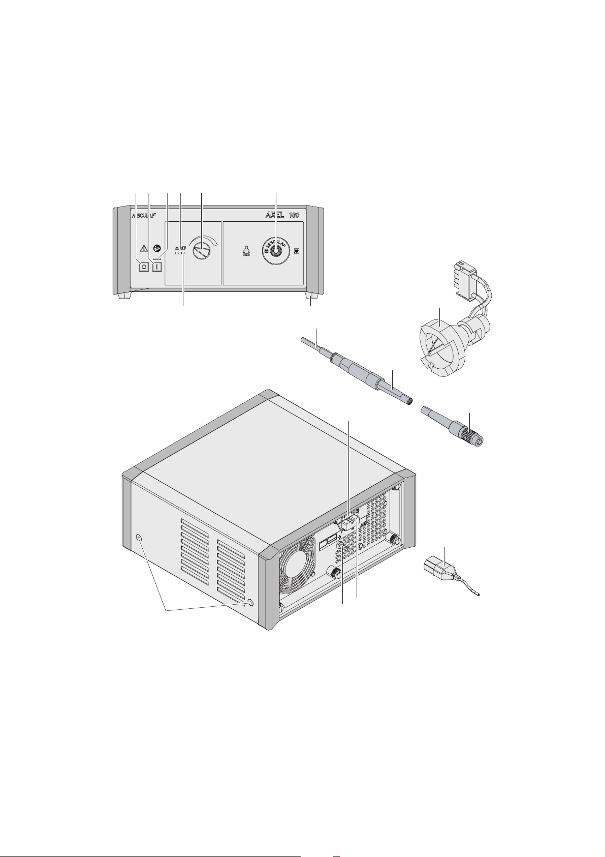
►Plug the power 14 cord into the socket 14 at the back of the control
unit.
►Plug in the mains plug at a socket of the building mains.
►Turn on the control unit with the power ON switch 2.
The power ON indicator 3lamp shows that the device is activated.
►When operating multiple devices concomitantly, connect the devices
to the potential equalization terminal.
4.2 Function checks
►Prior to each use, perform a functionality test for the xenon light
source.
►Make certain that the self-test runs in accordance with legal regula-
tions.
If the device is functioning properly, the xenon lamp 9will be ignited after
the device is switched on. After the device is switched on, the power ON
indicator 3on the front of the device is activated. After the self-test has
been successfully performed, the lamp OK indicator 4also comes on.
When the change lamp indicator 8is illuminated:
– The xenon lamp is malfunctioning
– Maximum permissible operating time has been exceeded
►Replace the xenon lamp, see Replacing xenon lamp.
4.3 Safe operation
Automatic self-test
After being switched on, the device automatically carries out a self-test
lasting approximately 3 seconds. During this self-test, all display elements
on the front panel are illuminated. After performance of the test, either
the lamp OK indicator 4or the change lamp indicator 8are activated,
depending upon the length of period during which the lamp has been
operated. If a malfunction is detected during the self-test, the lamp OK
indicator 4and change lamp indicator 8are illuminated simultaneously.
If this happens, the device must be restarted.
Switching the device on and off
►Turn on the control unit with the power ON switch 2.
►Turn off the control unit with the power OFF switch 1.
Brightness control
The desired brightness can be continuously adjusted with the brightness
control 5.
Note
If the cold light source is switched on and off frequently, the xenon lamp
will wear out more quickly. During brief interruptions, instead of switching
the device off, lower the brightness with the brightness control.
5. Validated reprocessing procedure
5.1 General safety instructions
Note
Adhere to national statutory regulations, national and international stan-
dards and directives, and local, clinical hygiene instructions for sterile pro-
cessing.
Note
For patients with Creutzfeldt-Jakob disease (CJD), suspected CJD or possi-
ble variants of CJD, observe the relevant national regulations concerning
the reprocessing of products.
Note
Mechanical reprocessing should be favored over manual cleaning as it
gives better and more reliable results.
Note
Successful processing of this medical device can only be ensured if the pro-
cessing method is first validated. The operator/sterile processing techni-
cian is responsible for this.
The recommended chemistry was used for validation.
Note
If there is no final sterilization, then a virucidal disinfectant must be used.
Note
For the latest information on reprocessing and material compatibility see
also the Aesculap extranet at www.extranet.bbraun.com
The validated steam sterilization procedure was carried out in the Aesculap
sterile container system.
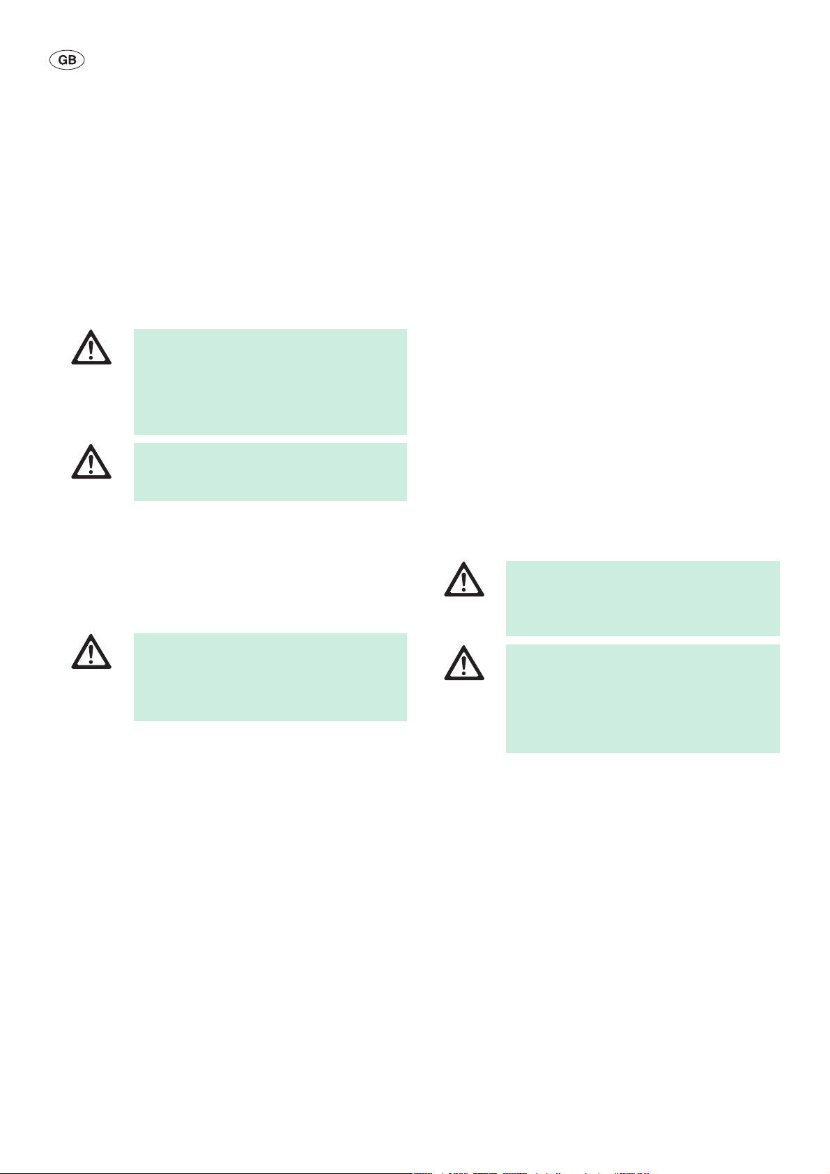
DANGER
Risk of fatal injury from electric shock!
►Connect the product only to a grounded power
supply.
►Set up the device in such a way that a separa-
tion from the network cable is straightforwardly
possible.
WARNING
Risk of injury and/or malfunction!
►Always carry out a function check prior to using
the product.

8
Aesculap®
Xenon Light Source OP930
5.2 General information
Dried or affixed surgical residues can make cleaning more difficult or inef-
fective and lead to corrosion. Therefore the time interval between appli-
cation and processing should not exceed 6 h; also, neither fixating pre-
cleaning temperatures >45 °C nor fixating disinfecting agents (active
ingredient: aldehydes/alcohols) should be used.
Excessive measures of neutralizing agents or basic cleaners may result in
a chemical attack and/or to fading and the laser marking becoming
unreadable visually or by machine for stainless steel.
Residues containing chlorine or chlorides e.g. in surgical residues, medi-
cines, saline solutions and in the service water used for cleaning, disinfec-
tion and sterilization will cause corrosion damage (pitting, stress corro-
sion) and result in the destruction of stainless steel products. These must
be removed by rinsing thoroughly with demineralized water and then dry-
ing.
Additional drying, if necessary.
Only process chemicals that have been tested and approved (e.g. VAH or
FDA approval or CE mark) and which are compatible with the product’s
materials according to the chemical manufacturers’ recommendations
may be used for processing the product. All the chemical manufacturer's
application specifications must be strictly observed. Failure to do so can
result in the following problems:
■Optical changes of materials, e.g. fading or discoloration of titanium or
aluminum. For aluminum, the application/process solution only needs
to be of pH >8 to cause visible surface changes.
■Material damage such as corrosion, cracks, fracturing, premature aging
or swelling.
►Do not use metal cleaning brushes or other abrasives that would dam-
age the product surfaces and could cause corrosion.
►Further detailed advice on hygienically safe and material-/value-pre-
serving reprocessing can be found at www.a-k-i.org, link to Publica-
tions, Red Brochure – Proper maintenance of instruments.
5.3 Dismantling prior to carrying out the reprocessing
procedure
►Disassemble the product immediately after use, as described in the
respective instructions for use.
5.4 Preparations at the place of use
►Remove any visible surgical residues to the extent possible with a
damp, lint-free cloth.
►Transport the dry product in a sealed waste container for cleaning and
disinfection within 6 hours.
5.5 Preparation before cleaning
►Keep the product separate from the power supply.
►Remove accessories.
►Carry out non-fixating/NaCl-free pre-cleaning immediately after use.
5.6 Cleaning/disinfection
Product-specific safety instructions for the reprocessing procedure
DANGER
Risk of electric shock and fire hazard!
►Unplug the device before cleaning.
►Do not use flammable or explosive cleaning or
disinfecting solutions.
►Ensure that no fluids will penetrate the product.
CAUTION
Damage to, or destruction of the product caused by
mechanical cleaning/disinfection!
►Only clean and disinfect the product manually.
►Do not sterilize the product under any circum-
stances.
CAUTION
Damage to the product due to inappropriate clean-
ing/disinfecting agents and/or excessive tempera-
tures!
►Only use cleaning/disinfecting agents approved
for surface cleaning. Follow the manufacturer’s
instructions for the respective cleaning/disin-
fecting agent.
►Observe specifications regarding concentration,
temperature and exposure time.

9
Validated cleaning and disinfection procedure
5.7 Wipe disinfection for electrical devices without sterilization
RT: Room temperature
Phase I
►Remove any visible residues with a disposable disinfectant wipe.
►Wipe all surfaces of the optically clean product with a fresh, disposable
disinfectant wipe.
►Observe the specified application time (1 min minimum).
5.8 Inspection, maintenance and checks
►Allow the product to cool down to room temperature.
►Inspect the product after each cleaning and disinfecting cycle to be
sure it is: clean, functional, and undamaged.
►Check the product for any damage, abnormal running noise, overheat-
ing or excessive vibration.
►Set aside the product if it is damaged.
6. Maintenance
To ensure reliable operation, the product must be maintained at least once
a year.
For technical service, please contact your national B. Braun/Aesculap
agency, see Technical Service.
The guaranteed service life of the xenon lamp is 500 hours of operation.
Note
Maintenance must only be carried out by authorized personnel. If neces-
sary, the circuit diagrams and the service manual, which contains all the
necessary documents, are provided for this.
6.1 Replacing xenon lamp
Validated procedure Special features Reference
Wipe disinfection for
electrical devices with-
out sterilization
■Keep the optical cable interfaces clean.
■Be sure that the optical cable interfaces are not scratched. Rub the
optical cable interfaces with a wad of cotton.
Chapter Wipe disinfection for electrical devices
without sterilization
Phase Step T
[°C/°F] t
[min] Conc.
[%] Water quality Chemical
IWipedisinfectionRT ≥1 - - Meliseptol HBV wipes 50 % Propan-1-ol
DANGER
Risk of fatal injury from electric shock!
►Pull out the power plug before opening the
device.
DANGER
Danger of explosion due to incorrect handling!
►The xenon lamp should only be operated by
qualified personnel.
►Always wear protective gloves and safety
glasses.
DANGER
Danger of burns from a hot xenon lamp!
►Only replace the xenon lamp after the device
has completely cooled down.

10
Aesculap®
Xenon Light Source OP930
Opening the device
►Rotate the fast-action locks 17 90° in a counterclockwise direction.
►Pull the cover slightly outwards and raise it.
►Make certain that the ground cable is not under any strain by being
pulled on.
Removing xenon lamp
Fig. 1
Legend
AWire loop
BPlug tabs
CLamp connector
DCeramic socket
ELamp body
►Loosen lamp connector C:
– Squeeze the laterally mounted plug tabs Btogether.
– Withdraw lamp connector Cat the same time.
►Release the wire loop Aon either side and fold them back.
►Grasp the xenon lamp by its ceramic socket Dand push it backwards.
At the same time incline the xenon lamp slightly downwards and open
the two fastening brackets.
Installing xenon lamp
Fig. 2
Legend
ABushing
BBushing flange
CGroove
DLamp connector
ECeramic socket
FPositioning flange
►Grasp the xenon lamp by its ceramic socket E.
►Incline the xenon lamp and its underside forwards.
►Insert the positioning flange Fof the xenon lamp in the groove Cof the
lamp holder and push it forward. Make certain that the lower edge of
the reflector touches the lamp holder.
►Push the xenon lamp forward until the upper segment of the edge of
the reflector touches the xenon lamp holder and the lamp snaps into
the two fastening brackets.
►Suspend the wire loop.
The xenon lamp is now fixed in place.
►Plug lamp plug Dinto bushing A. Ensure that the plug tabs snap into
place in the bushing flange B.
►Setting back the operating time counter, see Setting back the operat-
ing time counter
A
D
B
B
C
E
F
C
B
D
E
A

11
Closing the device
Note
Before putting the device cover in place, the connection between the cover
and the ground cable must be present and intact.
►Pull the device cover slightly outwards, by its lower edge.
►Set the cover on the device.
►Make certain that no wires are caught.
►Press the fast-action locks 17.
►Rotate the fast-action locks 17 clockwise 90° with a screwdriver until
it snaps into place.
Setting back the operating time counter
The xenon light source is equipped with an integrated operating time
counter that registers the number of hours the xenon lamp has been in
operation. If the xenon lamp exceeds the maximum permissible number of
hours in operation of 500 hours, the lamp change lamp indicator 8lights
up. After inserting the new xenon lamp, the operating time counter must
be reset.
►Switch on the device.
►Press on the two the lamp OK indicator 4and change lamp indicator 8
displays for approximately 3 seconds.
This sets the counter back.
The lamp OK 4and change lamp 8indicators flash alternately four times.
Then the lamp OK indicator light 4is illuminated.
7. Troubleshooting list
Malfunction Detection Cause Remedy
Xenon lamp and fan do not work Device not powered The plug is not inserted in the
socket
Insert plug in socket
Indicators not illuminated Fuses blown Replace fuses, see Fuse replace-
ment
Indicator light not illuminated even
after change of fuse
Malfunction in power supply unit Have xenon light source repaired
by manufacturer
Xenon lamp does not come on No light comes out of end of opti-
cal cable
Power ON switch not activated Activate power ON switch
The xenon lamp is malfunctioning Replace the xenon lamp
Malfunction in power supply unit Have xenon light source repaired
by manufacturer
Xenon lamp overheated Wait a few moments until the
xenon lamp is ignited
Fan does not work No air comes out of right grating Malfunction in fan Have xenon light source repaired
by manufacturer
Brightness noticeably poorer The optical cable cannot be
removed
Optical cable not completely
inserted
Use the correct optical cable con-
nection
Visual check of filter Thermal protection filter dirty Clean the thermal protection filter
Visual check of filter Malfunction in thermal protection
filter
Have xenon light source repaired
by manufacturer

12
Aesculap®
Xenon Light Source OP930
7.1 Fuse replacement
Specified fuses that can be used with this unit: TA020436 (T 4.0 AH/
250 V).
►Use a small screwdriver to release the clip on the fuse holder 15.
►Remove fuse holder 15.
►Replace both fuses.
►Reinsert fuse holder 15 so that it audibly snaps into place.
Note
If the fuses burn out frequently, the device is faulty and should be
repaired, see Technical Service.
8. Technical Service
►For service and repairs, please contact your national B. Braun/
Aesculapagency.
Modifications carried out on medical technical equipment may result in
loss of guarantee/warranty rights and forfeiture of applicable licenses.
Service addresses
Aesculap Technischer Service
Am Aesculap-Platz
78532 Tuttlingen / Germany
Phone: +49 (7461) 95 -1601
Fax: +49 (7461) 14 -939
E-Mail: ats@aesculap.de
Other service addresses can be obtained from the address indicated above.
9. Accessories/Spare parts
9.1 Optical cable accessories
9.2 Optical cable connection accessories
9.3 Accessories for power cord
9.4 Other accessories
9.5 Spare parts
DANGER
Risk of fatal injury from electric shock!
►Unplug the device before changing the fuses!
WARNING
Risk of injury and/or malfunction!
►Do not modify the product.
Art. no. Designation
OP906 Optical cable ∅=4.8mm,1800mmlong
OP913 Optical cable ∅=4.8mm,2500mmlong
OP914 Optical cable ∅=4.8mm,3500mmlong
Art. no. Designation
OP936 Optical cable connection system: Wolf
OP937 Optical cable connection system: Olympus
OP938 Optical cable connection system: ACMI
Art. no. Approvals Color Length
TE780 Europe black 1.5 m
TE730 Europe black 5.0 m
TE734 Great Britain black 5.0 m
TE735 USA, Canada, Japan gray 3.5 m
Art. no. Designation
TE736 Plug for isolation transformer
TA022012 Service manual
Art. no. Designation
OP931 Xenon lamp (180 W / 14.5 V)
TA020436 Fuses that can be used with this unit

13
10. Technical data
Classification acc. to Directive 93/42/EEC
10.1 Ambient conditions
Note
The atmospheric pressure of 770 hPa corresponds to a maximum operating
altitude of 2 500 m.
11. Disposal
Note
The user institution is obliged to process the product before its disposal, see
Validated reprocessing procedure.
►Detailed information concerning the disposal of the product is avail-
able through your national B. Braun/Aesculap agency, see Technical
Service.
Art.
no. Designation Class
OP930 Xenon light source I
Model OP930
Voltage range (current
consumption)
100Vto240V(5.5Ato2.3A)
Frequency 50 Hz to 60 Hz
Safety rating I
Device protection
Time-Current characteris-
tic
Breaking capacity
Construction
T 4.0 AH / 250 V
T (time lag)
H (1 500 A)
5 mm x 20 mm
Weight 6.5 kg
Dimensions L x W x H 305 mm x 305 mm x 125 mm
Applied partType CF
Xenon lamp 180 W xenon
Short-arc reflector lamp (14.5 V)
EMC IEC 60601-1-2
Norms applied IEC 60601-1
Operation Storage and transport
Temperature
Relative
humidity
Atmospheric
pressure
Adhere to national regulations when disposing of or recy-
cling the product, its components and its packaging!
The recycling pass can be downloaded from the Extranet
as a PDF document under the respective article number.
(The recycling pass includes disassembling instructions for
the product, as well as information for proper disposal of
components harmful to the environment.)
Products carrying this symbol are subject to separate col-
lection of electrical and electronic devices. Within the
European Union, disposal is taken care of by the manufac-
turer as a free-of-charge service.

14
Aesculap®
Xenon-Lichtquelle OP930
Aesculap®
Xenon-Lichtquelle OP930
Legende
1Schalter Netz AUS
2Schalter Netz EIN
3Anzeige Netz EIN
4Anzeige Lampe OK (innerhalb Lampenbetriebszeit)
5Helligkeitsregler
6Lichtleiteranschluss
7Gerätefüße
8Anzeige Lampenwechsel
9Xenon-Lampe
10 Lichtquellenanschluss
11 Lichtleiterkabel
12 Instrumentenanschluss
13 Gerätesteckdose
14 Netzkabel
15 Sicherungshalter
16 Anschluss Potenzialausgleich
17 Schnellverschlüsse
Symbole an Produkt und Verpackung
Vorsicht
Gebrauchsanweisung befolgen (weißes Männchen
auf blauem Grund)
Anwendungsteil des Typs CF
Lichtleiteranschluss
Anschluss für Potenzialausgleich
Anzeige: Lampenwechsel erforderlich
Anzeige: Lampe innerhalb erlaubter Betriebszeit
Gefährliche elektrische Spannung
Sicherung
Wechselstrom
Schalter Netz-EIN/AUS
Kennzeichnung von Elektro- und Elektronikgeräten
entsprechend Richtlinie 2002/96/EG (WEEE), siehe
Entsorgung

15
Inhaltsverzeichnis
1. Sichere Handhabung 15
1.1 Sichere Handhabung gemäß IEC-/VDE-Bestimmungen 16
1.2 Sicherheitshinweise zu XBO Reflektorlampen 16
2. Gerätebeschreibung 16
2.1 Lieferumfang 16
2.2 Zum Betrieb erforderliche Komponenten 16
2.3 Verwendungszweck 16
2.4 Funktionsweise 17
3. Vorbereiten und Aufstellen 17
3.1 Erstinbetriebnahme 17
3.2 Spannungsvorwahl 17
4. Arbeiten mit der Xenon-Lichtquelle 18
4.1 Bereitstellen 18
4.2 Funktionsprüfung 19
4.3 Bedienung 19
5. Validiertes Aufbereitungsverfahren 19
5.1 Allgemeine Sicherheitshinweise 19
5.2 Allgemeine Hinweise 20
5.3 Demontage vor der Durchführung des
Aufbereitungsverfahrens 20
5.4 Vorbereitung am Gebrauchsort 20
5.5 Vorbereitung vor der Reinigung 20
5.6 Reinigung/Desinfektion 20
5.7 Wischdesinfektion bei elektrischen Geräten ohne
Sterilisation 21
5.8 Kontrolle, Wartung und Prüfung 21
6. Instandhaltung 21
6.1 Xenon-Lampe austauschen 21
7. Fehler erkennen und beheben 23
7.1 Sicherungswechsel 24
8. Technischer Service 24
9. Zubehör/Ersatzteile 24
9.1 Zubehör Lichtleiterkabel 24
9.2 Zubehör Lichtleiteranschluss 24
9.3 Zubehör Netzkabel 24
9.4 Sonstiges Zubehör 24
9.5 Ersatzteile 24
10. Technische Daten 25
10.1 Umgebungsbedingungen 25
11. Entsorgung 25
1. Sichere Handhabung
►Produkt nur im Originalkarton transportieren.
►Vor der Anwendung des Produkts Funktionsfähigkeit und ordnungsge-
mäßen Zustand prüfen.
►„Hinweise zur elektromagnetischen Verträglichkeit (EMV)“ beachten,
siehe TA022130.
►Um Schäden durch unsachgemäßen Aufbau oder Betrieb zu vermeiden
und die Gewährleistung und Haftung nicht zu gefährden:
– Produkt nur gemäß dieser Gebrauchsanweisung verwenden.
– Sicherheitsinformationen und Instandhaltungshinweise einhalten.
– Nur Aesculap-Produkte miteinander kombinieren.
– Anwendungshinweise gemäß Norm einhalten, siehe Sichere Hand-
habung gemäß IEC-/VDE-Bestimmungen.
►Zubehör regelmäßig prüfen: Insbesondere sollten Elektrodenkabel und
endoskopisches Zubehör auf mögliche Beschädigungen an der Isola-
tion geprüft werden.
►Gebrauchsanweisung für den Anwender zugänglich aufbewahren.
►Gültige Normen einhalten.
►Sicherstellen, dass die elektrische Installation des Raums den IEC-
Anforderungen entspricht.
►Netzverbindung durch Ziehen am Stecker lösen, nie durch Ziehen am
Kabel.
►Xenon-Lichtquelle nicht in explosionsgefährdeten Bereichen einset-
zen.
WARNUNG
Verletzungsgefahr für den Patienten durch unsach-
gemäße Anwendung!
►Produkt und Zubehör nur von Personen betrei-
ben lassen, die die erforderliche Ausbildung,
Fachkenntnis oder Erfahrung haben.

16
Aesculap®
Xenon-Lichtquelle OP930
1.1 Sichere Handhabung gemäß IEC-/VDE-Bestim-
mungen
Operationsumfeld
►Xenon-Lichtquelle nur auf Höhen von max. 2500 m über N.N. betrei-
ben.
►Sicherstellen, dass die Umgebungstemperatur 35 °C nicht überschrei-
tet.
►Sicherstellen, dass die Lüftungsschlitze nicht verdeckt sind.
►Sicherstellen, dass die folgenden Mindestabstände zu anderen Geräten
eingehalten werden:
– zur Seite 50 mm
– nach hinten 60 mm
►Sicherstellen, dass nur Lichtleiter verwendet werden, die nicht elekt-
risch leitend sind. Dies gilt vor allem für Produkte anderer Hersteller,
um die CF-Bedingung zu gewährleisten.
►Um einen Ausfall der Xenon-Lampe während einer Operation zu ver-
meiden: Sicherstellen, dass die Xenon-Lampe nach der garantierten
Betriebszeit von 500 Stunden ausgetauscht wird. Betriebsstundenzäh-
ler beachten.
1.2 Sicherheitshinweise zu XBO Reflektorlampen
►Sicherstellen, dass Xenon-Lampen nur in geschlossener Xenon-Licht-
quelle betrieben werden.
►XBO-Lampen immer in mitgelieferter Schutzhülle bzw. mit Schutz-
kappe handhaben.
►Bei Wartungs- und Reparaturarbeiten immer Schutzkleidung tragen
(Schutzbrille und Handschuhe).
►Sicherstellen, dass bei Wartungs- und Reparaturarbeiten die Reflektor-
öffnung nicht auf Personen gerichtet ist.
2. Gerätebeschreibung
2.1 Lieferumfang
Hinweis
Die Xenon-Lichtquelle OP930 besitzt keine Ersatzlampe. Da vor Ablauf der
garantierten Betriebszeit die Xenon-Lampe ausfallen kann, immer eine
Ersatzlampe bereithalten, siehe Zubehör/Ersatzteile.
2.2 Zum Betrieb erforderliche Komponenten
2.3 Verwendungszweck
Die Xenon-Lichtquelle OP930 wird zur Ausleuchtung von Operationsfel-
dern und Körperhöhlen in der medizinischen Anwendung verwendet.
GEFAHR
Lebensgefahr durch elektrischen Stromschlag!
►Produkt nicht öffnen.
►Produkt nur an ein Versorgungsnetz mit Schutz-
leiter anschließen.
WARNUNG
Verletzungsgefahr durch Explosion!
►Sorgfältig mit der Xenon-Lampe umgehen. Der
Innendruck der Xenon-Lampe kann in kaltem
Zustand bis ca. 20 bar betragen.
►Xenon-Lampe nicht länger als die 1,25-fache
mittlere Lebensdauer verwenden. Während des
Betriebs steigt der Innendruck um das Dreifache
an.
WARNUNG
Verletzungsgefahr der Augen durch intensive UV-
Strahlung und hohe Leuchtdichte!
►Nicht direkt in die Xenon-Lampe sehen.
Art.-Nr. Bezeichnung
OP930 Xenon-Lichtquelle
OP935 Aesculap-Storz-Lichtleiteranschluss
TA009789 Gebrauchsanweisung Xenon-Lichtquelle OP930
TA022130 Hinweise zur elektromagnetischen Verträglichkeit
(EMV)
Art.-Nr. Bezeichnung
OP930 Xenon-Lichtquelle
TE730 bis TE780 Netzkabel
OP906
OP913
OP914
Lichtleiterkabel

17
2.4 Funktionsweise
Beim Einschalten des Geräts wird eine Xenon-Lampe gezündet. Die
Xenon-Lampe wird leistungsgeregelt betrieben.
Die Xenon-Lampe erzeugt zwischen zwei Elektroden einen frei brennen-
den Entladungsbogen in reinem Xenongas. Durch den geringen Abstand
der Elektroden kommt sie einer Punktlichtquelle sehr nahe.
Das Licht wird durch einen Kaltlichtreflektor gefiltert, in einen Lichtleiter
eingekoppelt und dem Betrachtungsfeld (OP-Feld) zugeführt.
Betriebszeitüberwachung der Xenon-Lampe
Die Xenon-Lichtquelle OP930 besitzt einen Betriebsstundenzähler, der die
Lampenbetriebszeit erfasst. Beim Betrieb leuchtet die Anzeige Xenon-
Lampe OK 4. Wird die max. Lampenbetriebszeit von 500 Betriebsstunden
überschritten, leuchtet die Anzeige Lampenwechsel 8.
Temperaturüberwachung
Um die Xenon-Lichtquelle vor Überhitzung zu schützen, wird die Betriebs-
temperatur des Netzteils und der Xenon-Lampe permanent überwacht.
Beim Überschreiten der Grenztemperatur wird die Xenon-Lampe ausge-
schaltet. Während der Abkühlphase sind die Lüfter aktiv. Die Xenon-Licht-
quelle ist nach kurzer Zeit wieder betriebsbereit.
Helligkeitsregelung
Die gewünschte Helligkeit wird stufenlos über den Helligkeitsregler 5ein-
gestellt.
3. Vorbereiten und Aufstellen
Wenn die folgenden Vorschriften nicht beachtet werden, übernimmt
Aesculap insoweit keinerlei Verantwortung.
►Beim Aufstellen und Betrieb des Produkts einhalten:
– die nationalen Installations- und Betreiber-Vorschriften,
– die nationalen Vorschriften über Brand- und Explosionsschutz.
Hinweis
Die Sicherheit des Anwenders und des Patienten hängt u. a. von einer intak-
ten Netzzuleitung, insbesondere von einer intakten Schutzleiterverbindung
ab. Defekte oder nicht vorhandene Schutzleiterverbindungen werden häu-
fig nicht sofort erkannt.
►Gerät über den an der Geräterückwand montierten Anschluss für
Potenzialausgleichsleiter mit dem Potenzialausgleich des medizinisch
genutzten Raums verbinden.
Hinweis
Die Potenzialausgleichsleitung ist unter der Art-Nr. GK535 (4 m lang) bzw.
TA008205 (0,8 m lang) beim Hersteller erhältlich.
3.1 Erstinbetriebnahme
3.2 Spannungsvorwahl
Die Netzspannung muss mit der Spannung übereinstimmen, die auf dem
Typenschild des Geräts angegeben ist.
GEFAHR
Explosionsgefahr durch falsches Aufstellen!
►Gerät nicht in explosionsgefährdeten Bereichen
benutzen.
►Sicherstellen, dass die Verbindung des Netzste-
ckers mit der Stromversorgung außerhalb
explosionsgefährdeter Bereiche vorgenommen
wird.
WARNUNG
Verletzungsgefahr und/oder Fehlfunktion des Pro-
dukts durch Fehlbedienung des medizinisch-elekt-
rischen Systems!
►Gebrauchsanweisungen aller medizinischen
Geräte einhalten.

18
Aesculap®
Xenon-Lichtquelle OP930
4. Arbeiten mit der Xenon-Lichtquelle
4.1 Bereitstellen
►Gerät auf ebener Fläche im nichtsterilen Bereich aufstellen.
►Sicherstellen, dass der Träger des Geräts (z. B. Tisch, Deckenampel,
Gerätewagen o. Ä.) ausreichend stabil ist.
►Sicherstellen, dass das Gerät während des Betriebs erschütterungsfrei
steht.
Zubehör anschließen
Zubehörkombinationen, die nicht in der Gebrauchsanweisung erwähnt
sind, dürfen nur verwendet werden, wenn sie ausdrücklich für die vorge-
sehene Anwendung bestimmt sind. Leistungsmerkmale sowie Sicherheits-
anforderungen dürfen nicht nachteilig beeinflusst werden.
Sämtliche Geräte, die an die Schnittstellen angeschlossen werden, müssen
darüber hinaus nachweislich die entsprechenden IEC-Normen erfüllen
(z. B. IEC 60950 für Datenbearbeitungsgeräte und IEC/DIN EN 60601-1
für medizinische elektrische Geräte).
Alle Konfigurationen müssen die Grundnorm IEC/DIN EN 60601-1 erfül-
len. Die Person, die Geräte miteinander verbindet, ist verantwortlich für
die Konfiguration und muss sicherstellen, dass die Grundnorm IEC/DIN
EN 60601-1 oder entsprechende nationale Normen erfüllt werden.
►Bei Fragen wenden Sie sich an Ihren B. Braun/Aesculap-Partner oder
den Aesculap Technischen Service, Adresse siehe Technischer Service.
Endoskop anschließen
►Endoskop am Instrumentenanschluss 12 anschließen.
Lichtleiterkabel anschließen
Das Endoskop muss am Instrumentenanschluss 12 angeschlossen sein.
►Lichtleiterkabel 11 am Lichtleiteranschluss 6einstecken, bis es einras-
tet.
►Lichtleiterkabel 11 nicht quetschen, knicken und nicht zu eng wickeln
(Mindestdurchmesser 150 mm).
Lichtleiterkabel von der Xenon-Lichtquelle trennen
►Nach der Operation Lichtleiter von Xenon-Lichtquelle trennen.
►Um zu verhindern, dass die Xenon-Lichtquelle verrutscht, Xenon-Licht-
quelle mit einer Hand festhalten und Lichtleiterkabel 11 mit der ande-
ren Hand ausstecken.
Lichtleiteranschluss wechseln
Die Xenon-Lichtquelle OP930 wird mit einem Aesculap-Storz-Lichtleiter-
anschluss geliefert. Dieser kann bei Bedarf durch die Lichtleiteranschluss-
Systeme Wolf (Art.-Nr. OP936), Olympus (Art.-Nr. OP937) und ACMI (Art.-
Nr. OP938) ausgetauscht werden, siehe Zubehör/Ersatzteile.
Sofern ein Lichtleiterkabel gesteckt ist, dieses entfernen:
►Lichtleiteranschluss 6gegen den Uhrzeigersinn drehen und entneh-
men.
►Anderen Lichtleiteranschluss 6einsetzen und im Uhrzeigersinn bis zum
Anschlag einschrauben.
Stets darauf achten, dass der Lichtleiteranschluss ausreichend fest mit
dem Gehäuse verbunden ist.
WARNUNG
Verbrennungsgefahr durch hohe Betriebstempera-
tur!
Xenon-Lampe, Lichtleiteraufnahme und Lichtlei-
teranschlüsse werden heiß.
►Lichtleiter nicht auf brennbaren Gegenständen,
wie z. B. OP-Tüchern ablegen.
WARNUNG
Blendgefahr durch Lichtstrahl!
►Niemals ins freie Ende eines angeschlossenen
Lichtleiters oder Endoskops sehen.
GEFAHR
Verletzungsgefahr durch unzulässige Konfiguration
bei Verwendung weiterer Komponenten!
►Sicherstellen, dass bei allen verwendeten Kom-
ponenten die Klassifikation mit der Klassifika-
tion des Anwendungsteils (Typ CF) des einge-
setzten Geräts übereinstimmt.
GEFAHR
Lebensgefahr durch elektrischen Stromschlag!
►Vor Demontage des Lichtleiteranschluss-Sys-
tems Netzstecker ziehen.
►Nicht in die Geräteöffnung fassen.
GEFAHR
Verbrennungsgefahr!
►Lichtleiteranschluss-System nur nach vollstän-
digem Abkühlen des Geräts austauschen.
►Nicht in die Geräteöffnung fassen.
►Gerät nicht ohne montiertes Lichtleiteran-
schluss-System in Betrieb nehmen.
Table of contents
Languages:
Other Braun Lighting Equipment manuals