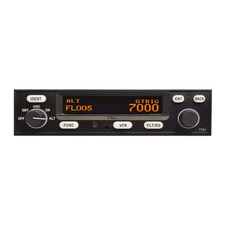
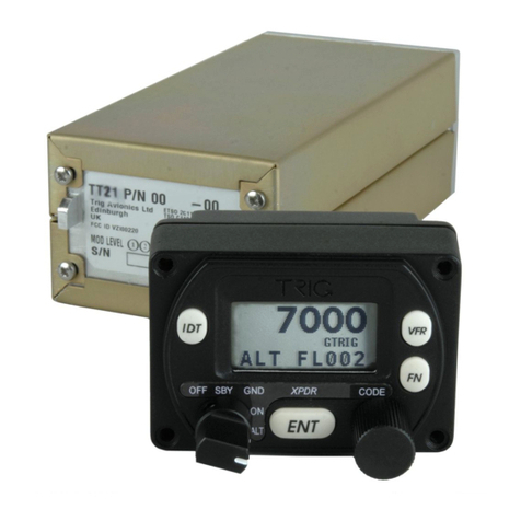
trig TT21 User manual

TT21 Mode S Transponder
Installation Manual
00560-00-AA
19 January 2009
Trig Avionics Limited
Heriot Watt Research Park
Riccarton, Currie
EH14 4AP
Scotland, UK
Copyright Trig Avionics Limited, 2009

This page intentionally left blank

TT21 Transponder Installation Manual 19 January 2009
00560-00 Issue AA
______________________
CONTENTS
1. PREFACE.......................................................................................................................................1
1.1 PURPOSE....................................................................................................................................1
1.2 SCOPE........................................................................................................................................1
1.3 CHANGES FROM PREVIOUS ISSUE ..............................................................................................1
1.4 DOCUMENT CROSS-REFERENCES ..............................................................................................1
2. INTRODUCTION..........................................................................................................................2
2.1 TT21 DESCRIPTION ...................................................................................................................2
2.2 INTERFACES...............................................................................................................................2
2.2.1 TT21 Transponder Unit....................................................................................................2
2.2.2 TC20 Controller Unit .......................................................................................................2
3. TECHNICAL SPECIFICATIONS...............................................................................................3
3.1 TT21 TRANSPONDER UNIT (00675-00).....................................................................................3
3.2 TC20 CONTROL UNIT (00649-00).............................................................................................4
4. UNIT AND ACCESSORIES SUPPLIED.....................................................................................5
4.1 TT21 MODE STRANSPONDER ITEMS ........................................................................................5
4.2 TC20 CONTROLLER ITEMS ........................................................................................................5
4.3 INSTALLATION KIT....................................................................................................................5
4.4 REQUIRED ITEMS.......................................................................................................................6
5. INSTALLATION ...........................................................................................................................7
5.1 UNPACKING AND INSPECTING EQUIPMENT................................................................................7
5.2 CONTROLLER MOUNTING..........................................................................................................7
5.3 TRANSPONDER MAIN UNIT MOUNTING.....................................................................................7
5.4 COOLING REQUIREMENTS .........................................................................................................7
5.5 TT21 TRANSPONDER ELECTRICAL CONNECTIONS.....................................................................8
5.5.1 TT21 Interface – Pinout....................................................................................................8
5.6 TT21 TRANSPONDER INTERFACE DETAILS................................................................................9
5.6.1 Power Input......................................................................................................................9
5.6.2 TMAP Bus.........................................................................................................................9
5.6.3 Power On..........................................................................................................................9
5.6.4 Controller Power..............................................................................................................9
5.6.5 Mutual Suppression..........................................................................................................9
5.6.6 Ident Switch Input.............................................................................................................9
5.6.7 Squat Switch Input............................................................................................................9
5.6.8 External Standby Input...................................................................................................10
5.6.9 GPS Position Input.........................................................................................................10
Trig Avionics Limited i

TT21 Transponder Installation Manual 19 January 2009
00560-00 Issue AA
______________________
5.7 TC20 CONTROLLER ELECTRICAL CONNECTIONS ....................................................................10
5.7.1 TC20 Interface - Pinout..................................................................................................10
5.8 TC20 CONTROLLER INTERFACE DETAILS................................................................................10
5.8.1 TMAP Bus.......................................................................................................................10
5.8.2 Altitude Out ....................................................................................................................11
5.8.3 Remote ON......................................................................................................................11
5.8.4 Power..............................................................................................................................11
5.9 DCONNECTOR CRIMP TERMINALS..........................................................................................11
5.10 WIRING CONSIDERATIONS.......................................................................................................11
5.11 ANTENNA INSTALLATION........................................................................................................12
5.11.1 Antenna Ground Plane...................................................................................................12
5.11.2 Antenna Cable ................................................................................................................ 12
5.11.3 TNC Connector...............................................................................................................14
5.12 STATIC PRESSURE CONNECTION..............................................................................................14
6. INSTALLATION SETUP AND TEST.......................................................................................16
6.1 CONFIGURATION ITEMS...........................................................................................................16
6.1.1 Aircraft Address Programming ......................................................................................16
6.1.2 VFR Squawk Code..........................................................................................................16
6.1.3 VFR Flight ID.................................................................................................................16
6.1.4 Airspeed Category..........................................................................................................17
6.1.5 Aircraft Category............................................................................................................17
6.1.6 Squat Switch Source .......................................................................................................17
6.1.7 GPS Input .......................................................................................................................17
6.1.8 GPS Line Speed..............................................................................................................17
6.1.9 GPS System Integrity Level ............................................................................................17
6.1.10 Aircraft Length and Width..............................................................................................17
6.1.11 ADS-B Test Message Options.........................................................................................18
6.2 TEST AND CALIBRATION ITEMS ...............................................................................................18
6.2.1 Voltage Check.................................................................................................................18
6.2.2 Altitude Encoder Calibration .........................................................................................18
7. POST INSTALLATION CHECKS............................................................................................20
8. NORMAL OPERATION.............................................................................................................21
8.1 OVERVIEW...............................................................................................................................21
8.2 DISPLAY..................................................................................................................................21
8.3 MODE SELECTOR KNOB ..........................................................................................................21
8.4 PUSH BUTTONS........................................................................................................................21
8.5 CODE SELECTOR KNOB ...........................................................................................................22
ii Trig Avionics Limited

TT21 Transponder Installation Manual 19 January 2009
00560-00 Issue AA
______________________
8.6 ALTITUDE ENCODER WARM UP..............................................................................................22
8.7 GENERAL LOW TEMPERATURE OPERATION.............................................................................22
8.8 WARNING MESSAGES..............................................................................................................22
8.9 FAULT ANNUNCIATION............................................................................................................22
9. CONTINUED AIRWORTHINESS............................................................................................24
10. LIMITED WARRANTY .........................................................................................................25
11. ENVIRONMENTAL QUALIFICATION FORMS ..............................................................26
12. ADS-B COMPLIANCE ...........................................................................................................28
12.1 ADS-B PARAMETERS SUPPORTED ..........................................................................................28
12.2 ADS-B SERVICE LEVELS.........................................................................................................28
12.3 AMC 20-24 COMPLIANCE....................................................................................................... 29
13. INSTALLATION DRAWINGS..............................................................................................30
13.1 MOUNTING TRAY FIXING AND OVERALL DIMENSIONS..............................................................30
13.2 FRONT PANEL CUT-OUT OPTIONS ...........................................................................................31
14. BASIC INTERCONNECT DIAGRAM .................................................................................33
Trig Avionics Limited iii

TT21 Transponder Installation Manual 19 January 2009
00560-00 Issue AA
______________________
iv Trig Avionics Limited
This page intentionally left blank

TT21 Transponder Installation Manual 19 January 2009
00560-00 Issue AA
______________________
1. Preface
1.1 Purpose
This manual describes the physical and electrical characteristics and the installation requirements for a
TT21 Mode S Transponder and associated TC20 controller.
1.2 Scope
This document applies to the installation of the TT21 Mode S Transponder.
At the publication date of this manual the software version identifier for the TT21 is 1.1 and the FPGA
version identifier is 1.1. The TC20 controller software version identifier is 1.1. The software and
FPGA versions are subject to change without notice.
1.3 Changes from Previous Issue
None, this is the first issue.
1.4 Document Cross-References
00559-00 TT21 Mode S Transponder Operating Manual AA
Trig Avionics Limited Page 1

TT21 Transponder Installation Manual 19 January 2009
00560-00 Issue AA
______________________
2. Introduction
2.1 TT21 Description
The TT21 Mode S transponder system is an ED-73B Class 2 compliant Mode S level 2 datalink
transponder, with support for extended squitter, which also meets the relevant environmental
requirements of ED-14D. It is certified to ETSO 2C112b and ETSO C166a.
The TT21 transponder is controlled using a separate front panel controller, called the TC20. This
allows the transponder to be mounted separately from the instrument panel, and reduces the amount of
panel space taken by the transponder. The TC20 includes an altitude encoder. The TC20 is certified to
ETSO 2C112b and ETSO C88a.
The TT21 transmitter power output is nominally 130 watts, and the transponder runs from either 14
volt nominal or 28 volt nominal DC power supply with no configuration changes required.
The TT21 transponder responds to both legacy Mode A/C interrogations and to Mode S interrogations
from both ground radar and airborne collision avoidance systems. In all cases, the interrogations are
received by the transponder on 1030MHz, and replies are transmitted on 1090MHz.
2.2 Interfaces
2.2.1 TT21 Transponder Unit
The main transponder unit has a single TNC antenna connection and a single 25 way D-type connector.
The 25 way D-type interface provides the following services:
Power Input The TT21 operates on 11 to 33 Volts DC.
Front Panel Datalink A two wire data link is used to connect the TT21 and the controller.
Front Panel Power The controller is powered from the transponder.
Remote On/Off The on-off switching is on the controller, and switches this input.
Ident input External IDENT switch input.
Standby input External standby input for dual transponder installations.
“On ground” input Allows automatic flight/ground mode switching for aircraft with a squat switch.
Suppression bus I/O ARINC compatible suppression bus signal used in aircraft with other pulse
equipment, such as DME. This pin is both an input to and output from the
transponder.
GPS Input Connection to a GPS supplying position input for ADS-B position reporting.
RS232 Output Secondary RS232 interface provided for future upgrade.
2.2.2 TC20 Controller Unit
The TC20 controller has a single 9 way D-type connector. It provides the following services:
Power Input The controller receives power from the transponder.
Front Panel Datalink A two wire data link is used to connect the TT21 and the controller.
Remote On/Off The on-off switching is on the controller, and controls this output.
Altitude Output An additional serial output on the TC20 provides pressure altitude information
that can be used for baro-aiding by certain GPS receivers.
Page 2 Trig Avionics Limited

TT21 Transponder Installation Manual 19 January 2009
00560-00 Issue AA
______________________
3. Technical Specifications
3.1 TT21 Transponder Unit (00675-00)
Specification Characteristics
Compliance ETSO 2C112b Class 2 Level 2es, ETSO C166a Class B0
FCC Identification VZI00675
Applicable documents EuroCAE ED-73B, EuroCAE ED-14E (RTCA DO-160E),
RTCA DO-181D, RTCA DO-260A change 2
Software ED-12B (RTCA DO-178B) Level B
Hardware DO-254 Level C
Power Requirements 11 – 33 Volts DC. Typical 5 Watts @ 14Volts.
Altitude 35,000 feet
Humidity 95% @ +50°C for 6 hours; 85% @ +38°C for 16 hours.
Tested to Category A in DO-160E
Operating Temperature -20°C to +70°C
Transmitter Frequency 1090MHz ± 1MHz
Transmitter Power 130 Watts nominal; 71 Watts minimum at antenna after
allowing for 0.5dB connector losses and 1.5dB cable losses.
Receiver Frequency 1030 MHz
Receiver Sensitivity -74dBm ± 3dB
Physical Specifications (in the
mounting tray)
Height 48mm (1.9”)
Width 66mm (2.5”)
Length 160mm (6.3”)
Weight 0.77lbs. (350 g)
Trig Avionics Limited Page 3

TT21 Transponder Installation Manual 19 January 2009
00560-00 Issue AA
______________________
3.2 TC20 Control Unit (00649-00)
Specification Characteristics
Compliance ETSO 2C112b, ETSO C88a
Applicable documents EuroCAE ED-73B, EuroCAE ED-14E (RTCA DO-160E),
RTCA DO-181D, SAE 8003
Software ED-12B (RTCA DO-178B) Level B
Altitude -1000 to 35,000 feet
Humidity 95% @ +50°C for 6 hours; 85% @ +38°C for 16 hours.
Tested to Category A in DO-160E
Operating Temperature -20°C to +55°C
Physical Specifications (behind the
panel)
Height 44mm (1.8”)
Width 63mm (2.4”)
Length 54mm (2.1”)
Weight 0.11lbs. (90 g)
Page 4 Trig Avionics Limited

TT21 Transponder Installation Manual 19 January 2009
00560-00 Issue AA
______________________
4. Unit and Accessories supplied
4.1 TT21 Mode S Transponder Items
The TT21 Mode S transponder includes the following items:
Unit Description Qty Part Number
TT21 Mode S Transponder 1 00675-00
TT21 Mounting Tray 1 00667-00
4.2 TC20 Controller Items
The TC20 controller includes the following items:
Unit Description Qty Part Number
TC20 Transponder Controller 1 00649-00
TT21 Installation Kit 1 00668-00
4.3 Installation Kit
The TT21 installation kit includes the following items:
Unit Description Qty Part Number
TT21 Transponder Installation Manual 1 00560-00
TT21 Pilots Operating Manual 1 00559-00
Mounting adapter (circular hole adapter) 2 00678-00
Connector Co-axial TNC 1 00723-00
Screwlock assembly 4 00724-00
Headshell, 9 Way 1 00725-00
Headshell, 25 way 1 00726-00
9 way D-type contact housing (female) 1 00727-00
25 way D-type contact housing (male) 1 00728-00
Crimp Terminal, Male, 22-24 AWG 20 00729-00
Crimp Terminal, Female, 22-24 AWG 9 00730-00
Static tubing, EPDM 5mm ID 1 00731-00
Hose T piece 1 00732-00
Hose Adapter 2 00733-00
Hose clip, small 6 00734-00
Hose clip, large 2 00735-00
Long mounting screws, 4-40 thread 4 00736-00
Short mounting screws, 4-40 thread 4 00737-00
Trig Avionics Limited Page 5

TT21 Transponder Installation Manual 19 January 2009
00560-00 Issue AA
______________________
4.4 Required Items
Additional items you will require, but which are not in the TT21 package, include:
Antenna and fixing hardware. The TT21 is compatible with any transponder antenna
approved to ETSO C74 or 2C112.
Cables. You need to supply and fabricate all required cables. Guidance on cable types is
given in section 5 below.
Fixings. To secure the transponder tray to the airframe you will need at least 3 flat head
screws and three self-locking nuts. If the aircraft does not have existing mounting provisions
you may need to fabricate additional brackets to support the transponder tray.
To support the optional ADS-B features a GPS receiver with an appropriate serial output is required.
Page 6 Trig Avionics Limited

TT21 Transponder Installation Manual 19 January 2009
00560-00 Issue AA
______________________
5. Installation
5.1 Unpacking and Inspecting Equipment
Carefully unpack the transponder and make a visual inspection of the unit for evidence of any damage
incurred during shipment. If the unit is damaged, notify the shipping company to file a claim for the
damage. To justify your claim, save the original shipping container and all packaging materials.
5.2 Controller Mounting
The TC20 transponder controller must be mounted rigidly in the aircraft panel. The controller can be
mounted in the ultra compact mounting hole or in a conventional 57mm (2¼ inch) instrument cut-out.
The following installation procedure should be followed, remembering to allow adequate space for
installation of cables and connectors.
Select a position in the panel that is not too close to any high external heat source. (The
TC20 is not a significant heat source itself and does not need to be kept away from other
devices for this reason).
Avoid sharp bends and placing the cables too near to the aircraft control cables.
If you are using a 57mm instrument cut-out, you must first clip the two mounting adapters to the
transponder. The controller should then be mounted using the four LONG screws provided. If you are
using the Trig compact cutout, you do not need the mounting adapters. The controller should be
mounted using the four SHORT screws provided. If alternate screws are required, please note that the
mounting thread in each case is 4-40.
5.3 Transponder Main Unit Mounting
The TT21 Mode S transponder is designed to be mounted in any convenient location in the cockpit, the
cabin, or an avionics bay.
The following installation procedure should be followed, remembering to allow adequate space for
installation of cables and connectors.
Select a position in the aircraft that is not too close to any high external heat source. (The
TT21 is not a significant heat source itself and does not need to be kept away from other
devices for this reason).
Avoid sharp bends and placing the cables too near to the aircraft control cables.
Secure the mounting tray (p/n 00667-00) to the aircraft via the three (3) mounting holes in the
tray. The tray should be mounted to a flat surface - it is important that the tray is supported at
the dimples as well as the three mounting points.
Put the TT21 transponder into the secured mounting tray by hooking the connector end under
the lip on the tray.
Lock the TT21 transponder into the mounting tray by clipping the retaining wire over the lugs
on the opposite end.
5.4 Cooling Requirements
The TT21 Mode S transponder meets all applicable ETSO requirements without forced air-cooling.
Attention should however be given to the incorporation of cooling provisions to limit the maximum
operating temperature if the TT21 is installed in close proximity to other avionics. The reliability of
equipment operating in close proximity in an avionics bay can be degraded if adequate cooling is not
Trig Avionics Limited Page 7

TT21 Transponder Installation Manual 19 January 2009
00560-00 Issue AA
______________________
provided.
5.5 TT21 Transponder Electrical Connections
The TT21 has a single 25 way female socket which provides the data and power inputs to the
transponder. A single TNC coaxial connector attaches to the antenna.
5.5.1 TT21 Interface – Pinout
Pin Signal Direction
1 Ground -
2 TMAP1A Bidirectional
3 TMAP1B Bidirectional
4 Ground -
5 GPS Position In Input
6 Ground -
7 RS232 Out Output
8 TMAP2A Bidirectional
9 TMAP2B Bidirectional
10 Ground -
11 Controller Power Output
12 Ground -
13 Power ON Input
14 Ground -
15 11-33V DC Input
16 Reserved -
17 Squat Switch In Input
18 Mutual Suppression Bidirectional
19 External Standby In Input
20 Ident Switch In Input
21 Reserved -
22 Reserved -
23 Reserved -
24 Reserved -
25 Reserved -
The following diagram shows the connector orientation as viewed from the wiring side.
Page 8 Trig Avionics Limited

TT21 Transponder Installation Manual 19 January 2009
00560-00 Issue AA
______________________
5.6 TT21 Transponder Interface Details
5.6.1 Power Input
The power supply can be 11-33 Volts DC; no voltage adjustment is required.
Use a 3 Amp circuit breaker for power supply protection to the TT21.
5.6.2 TMAP Bus
TMAP is a Trig proprietary bus based on RS485 signalling. It provides a bi-directional interface
between the transponder and the control head. Each TMAP interface comprises a balanced pair of
signals, called A and B, both of which must be connected for communication to work.
There are two sets of TMAP pins on the TT21, TMAP1 A and B, and TMAP2 A and B. This is to
support future installation wiring options. The two sets are identical, and either pair (TMAP1 or
TMAP2) may be used to connect to the control head.
5.6.3 Power On
The TT21 power supply can be directly controlled by this discrete input. The input is active low, so
that the TT21 will power up whenever the input is held low. This signal is intended to connect to the
TC20 Remote ON output.
5.6.4 Controller Power
The TC20 controller does not connect to aircraft power – it receives power from the TT21 using this
output. The TT21 provides 6.5 Volts to the TC20. This output includes short circuit protection, and
no fuse is required between the TT21 and the TC20.
5.6.5 Mutual Suppression
Mutual suppression allows two or more transmitters on adjacent frequencies to inhibit the other
transmitters when one is active to limit the interference effects. It is commonly used between
transponders and DME systems, and between transponders and collision avoidance systems.
The Suppress I/O on pin 18 is an ARINC compatible suppression bus interface, which acts as both an
input and an output. The TT21 will assert this signal when it is transmitting, and can be suppressed by
other equipment that asserts the signal. The TT21 will drive approximately 24 Volts on the output
(independently of supply voltage), and will treat the input as active whenever the bus has greater than
10 Volts.
5.6.6 Ident Switch Input
The Ident switch input allows the IDENT function to be selected using a remote switch. The input is
active low, and will be asserted when the voltage to ground is pulled below approximately 4 Volts.
5.6.7 Squat Switch Input
The Squat switch input allows the transponder to automatically switch between Airborne and Ground
modes. The input will be asserted when the voltage to ground is pulled below approximately 4 Volts.
The logical sense of the input can be programmed to be either active low or active high.
On an aircraft with no squat switch this input should be left unconnected, and the transponder
programmed to ignore the input.
Trig Avionics Limited Page 9

TT21 Transponder Installation Manual 19 January 2009
00560-00 Issue AA
______________________
5.6.8 External Standby Input
This input, when held low, places the transponder in Standby mode. It should be used to switch
between transponders in an installation with two transponders. The input is active low, and will be
asserted when the voltage to ground is pulled below approximately 4 Volts.
5.6.9 GPS Position Input
The GPS position input is required to support ADS-B functionality. The GPS position input is an
RS232 input to the transponder. The ADS-B features are optional – no GPS is required for normal
Mode S Elementary Surveillance.
The TT21 GPS input can recognise the industry standard “Aviation” format, the NMEA 0183 format,
or the format used by certain Freeflight and NexNav GPS sensors; the interface speed can be selected
between 4800, 9600 and 19200 bps.
There is also an RS232 output on the connector for future expansion. This pin is unused and should be
left unconnected.
5.7 TC20 Controller Electrical Connections
The TC20 controller has a single 9 way D type male connector to link to the transponder, and
optionally to connect to a GPS for baro-aiding.
5.7.1 TC20 Interface - Pinout
Pin Signal Direction
1 Ground -
2 TMAPA Bidirectional
3 TMAPB Bidirectional
4 Altitude Out Output
5 Reserved Input
6 Ground -
7 Remote ON Output
8 Power Input
9 Ground -
The following diagram shows the connector orientation as viewed from the wiring side.
5.8 TC20 Controller Interface Details
5.8.1 TMAP Bus
TMAP is a Trig proprietary bus based on RS485 signalling. It provides a bi-directional interface
between the transponder and the control head. Each TMAP interface comprises a balanced pair of
Page 10 Trig Avionics Limited

TT21 Transponder Installation Manual 19 January 2009
00560-00 Issue AA
______________________
signals, called A and B, both of which must be connected for communication to work.
TMAP A and B lines on the controller should be connected to the corresponding A and B lines of
either TMAP1 or TMAP2 on the TT21.
5.8.2 Altitude Out
The TC20 incorporates an altitude encoder. Certain GPS receivers can benefit from having altitude
information supplied to them. The TC20 reports pressure altitude on this pin as an RS232 serial data
format, at 9600 bps, using the format commonly called “Icarus” or “Garmin” format.
5.8.3 Remote ON
This output is connected directly to the Power/Mode switch on the TC20, and should be connected to
the Power ON discrete input of the TT21.
5.8.4 Power
The TC20 uses 6.5 volts which is available from the TT21 transponder. This input should NOT be
connected to aircraft power.
5.9 D Connector Crimp Terminals
The D type connector contacts should be wired with wire of 20-24 AWG. The contacts are compatible
with a wide range of crimp tools.
Once crimped, the contacts should be slotted into the rear of the connector shell. Push the contact in
until the retaining tab clicks into place. Tug gently to confirm the contact is locked in place.
5.10 Wiring Considerations
The connection from the TT21 transponder to the TC20 uses a minimum of six (6) signal lines; the
TMAP pair, the Power and Ground pair, and the Remote On discrete line plus associated ground line.
In a certified installation the normal wire choice would be Tefzel hook-up wire. Wire of 20 AWG is
more than adequate for the task; in installations where weight is an issue, wire of 22 or 24 AWG can
also be used. Where lighter wires than 20 AWG are used the individual wires should be laced together
for support.
The TT21/TC20 was tested and certified using unshielded, untwisted wiring, and that is sufficient for a
certified installation. There may however be technical benefits of improved electromagnetic emissions
and susceptibility to and from the transponder system if the two wires of the TMAP pair are lightly
twisted together – one twist per 1 to 2 inches is appropriate. This may reduce interference and break-
through on adjacent audio wiring if it is not possible to route them separately. For tidiness and
consistency the other pairs in the bundle can also be twisted, but there will be no particular difference
in behaviour.
The distance between the TT21 transponder and the TC20 controller is limited by the impedance of the
wire between them. The TC20 is powered from the TT21, not from aircraft power, and therefore the
acceptable voltage drop in the power line is what limits the distance. The TC20 needs an impedance of
less than 0.5 ohm in the power line for satisfactory operation. The following table gives guidelines for
typical aircraft hook-up wire. Note that different brands may vary – check your supplier for details.
Gauge Ohm/k
m Length for 0.5
Ohm
20
AWG 35 14.2 m
22 64 7.8 m
Trig Avionics Limited Page 11

TT21 Transponder Installation Manual 19 January 2009
00560-00 Issue AA
______________________
AWG
24
AWG 99 5.0 m
An alternative to a harness built from individual wires, particularly for a long cable run, is to use a
multi-core cable. Aviation grade cable with 6 or more cores is often more expensive than the
individual wires, and therefore is not generally a good choice for a certified aircraft. For aircraft where
those considerations do not apply however, an attractive alternative solution may be to use 3 pair or 4
pair data cable.
Whilst appropriate cables may exist, please note that not all data cable is suitable for this application.
Cables with solid cores should not be used, and cables should be selected based on the wear
characteristics of their insulation material, including temperature rating, resistance to solvents and oils,
and flammability. Most inexpensive commercial data cables have poor flammability properties.
5.11 Antenna Installation
The antenna should be installed according to the manufacturer’s instructions.
The following considerations should be taken into account when siting the Antenna.
The antenna should be well removed from any projections, the engine(s) and propeller(s). It
should also be well removed from landing gear doors, access doors or others openings which
will break the ground plane for the antenna.
The antenna should be mounted on the bottom surface of the aircraft and in a vertical position
when the aircraft is in level flight.
Avoid mounting the antenna within 3 feet of the ADF sense antenna or any COMM antenna
and 6 feet from the transponder to the DME antenna.
Where practical, plan the antenna location to keep the cable lengths as short as possible and
avoid sharp bends in the cable to minimise the VSWR.
Electrical connection to the antenna should be protected to avoid loss of efficiency as a result of the
presence of liquids or moisture. All antenna feeders shall be installed in such a way that a minimum of
RF energy is radiated inside the aircraft.
5.11.1 Antenna Ground Plane
When a conventional aircraft monopole antenna is used it relies on a ground plane for correct
behaviour. For ideal performance the ground plane should be very large compared to the wavelength
of the transmission, which is 275mm. In a metal skinned aircraft this is usually easy to accomplish, but
is more difficult in a composite or fabric skinned aircraft. In these cases a metallic ground plane
should be fabricated and fitted under the antenna.
As the ground plane is made smaller, the actual dimensions of the ground plane become more critical,
and small multiples of the wavelength should be avoided, as should circles. Rectangles or squares are
much less likely to create a critical dimension that resonates with the transmissions. The smallest
practical ground plane is a square around 120mm per side; as the size increases the performance may
actually get worse, but will be better by the time the ground plane is 700mm on each side. Anything
much larger than that size is unlikely to show significant further improvement.
The thickness of the material used to construct the ground plane is not critical, providing it is
sufficiently conductive. A variety of proprietary mesh and grid solutions are available. Heavyweight
cooking foil meets the technical requirements, but obviously needs to be properly supported.
5.11.2 Antenna Cable
The TT21 is designed to meet Class 2 requirements with an allowance of 2 dB for loss in the
Page 12 Trig Avionics Limited

TT21 Transponder Installation Manual 19 January 2009
00560-00 Issue AA
______________________
connectors and cable used to connect it to the antenna. Excessive loss will degrade both transmitter
output power and receiver sensitivity.
Allowing 0.25dB loss for the connector at each end of the antenna cable assembly leaves an allowance
of 1.5dB maximum loss for the cable itself.
An acceptable cable:
Has less than 1.5dB loss for the run length needed
Has a characteristic impedance of 50 Ohms
Has double braid screens or has a foil and braid screen
Once the cable run length is known, a cable type with low enough loss per metre that meets the above
requirements can be chosen. Longer runs require lower loss cable. Consider moving the TT21 closer
to the antenna to minimise the losses in the antenna cable – subject to the limits identified above, the
TT21 can be at any distance from the control head without affecting performance in any way.
NOTE: Low loss cable typically uses foamed or cellular dielectrics and foil screens. These make such
cables especially prone to damage from too-tight bends or from momentary kinking during installation.
Once kinked, these cables do not return to full performance when straightened.
The following table is a guide to the maximum usable lengths of some common cable types. Actual
cable loss varies between manufacturers, there are many variants, and the table is therefore based on
typical data. Use it as a guide only and refer to the manufacturer’s data sheet for your specific chosen
cable for accurate values.
Max Length
in Metres Max Length
in Feet Insertion Loss
dB/metre at
1090MHz
MIL-C-17 Cables Electronic Cable
Specialists Type
2.54 8’ 4” 0.59 M17/128 (RG400)
3.16 10’ 4” 0.47 3C142B
3.81 12’ 6” 0.39 M17/112 (RG304)
5.25 17’ 3” 0.29 M17/127 (RG393) 311601
6.42 21’ 1” 0.23 311501
8.22 26’ 11” 0.18 311201
12.59 41’ 3” 0.12 310801
Contact Electronic Cable Specialists on +1 414 421 5300 or www.ecsdirect.com for their data sheets.
When routing the cable, ensure that you:
Route the cable away from sources of heat.
Route the cable away from potential interference sources such as ignition wiring, 400Hz
generators, fluorescent lighting and electric motors.
Allow a minimum separation of 300mm (12 inches) from an ADF antenna cable.
Keep the cable run as short as possible.
Avoid routing the cable round tight bends.
Avoid kinking the cable even temporarily during installation.
Secure the cable so that it cannot interfere with other systems.
Trig Avionics Limited Page 13

TT21 Transponder Installation Manual 19 January 2009
00560-00 Issue AA
______________________
5.11.3 TNC Connector
This section describes the technique for attaching the antenna cable to the supplied TNC connector.
If a low-loss cable is needed that has too large a dielectric diameter to fit the supplied connector, a
short length (up to 150mm or 6 inches) of smaller cable may be used with suitable mating connectors
to adapt to the transponder connector.
The supplied connector can be completed using a wide range of commercial crimp tools (for example
the Tyco 5-1814800-3). The die apertures for the inner pin and the outer shield should be
approximately 1.72 mm and 5.41 mm respectively.
Strip back the coax cable to the dimensions in the table, as shown in the diagram below. Slide
25 mm (1 inch) of heat shrink tubing over the cable.
Slide the outer crimp sleeve over the cable – it must go on before securing the centre contact.
Dimension Cut size
(mm) Cut size
(inches)
A 17.5 0.69
B 7.2 0.28
C 4.8 0.19
Crimp the centre contact to the cable.
Insert the cable into the connector – the centre contact should click into place in the body, the
inner shield should be inside the body of the connector and the outer shield should be outside
the body.
Crimp the outer sleeve over the shield.
Slide heat shrink tubing forward (flush to connector) and heat to shrink the tubing.
5.12 Static Pressure Connection
The TC20 controller includes an altitude encoder which must be connected to the same source of static
pressure as the primary altimeter on the aircraft. The TC20 static pressure port provides a mounting
spigot intended for nominal 5mm or 3/16 inch inside diameter tubing. A length of 5mm EPDM rubber
tubing is included in the installation kit to facilitate connection to the aircraft static system.
Choose a point in the existing static pressure line that is as close as practical to the TC20. Cut the
static pressure line, and use the supplied T fitting to connect the altitude encoder. Take care not to
contaminate the inside of the static line when cutting or inserting the connectors.
Page 14 Trig Avionics Limited
Other manuals for TT21
2
Table of contents
Other trig Marine Radio manuals
Popular Marine Radio manuals by other brands

Honeywell
Honeywell Esser RZT 8000 Installation instruction
Uniden
Uniden MC 795 operating guide
GME
GME GX600D instruction manual
UPS Aviation Technologies
UPS Aviation Technologies Apollo SL70R installation manual

Raymarine
Raymarine Ray 90 Installation & operating instruction
Honeywell
Honeywell ESSER IQ8FCT Installation instruction

