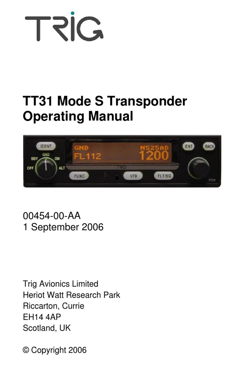
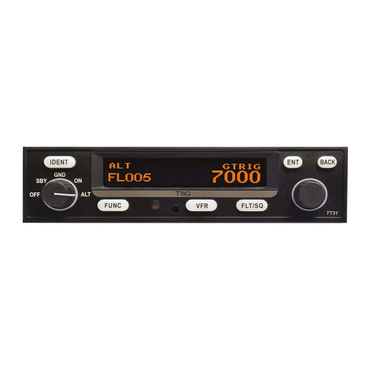
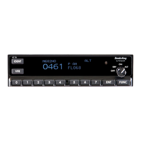
trig TT21 User manual

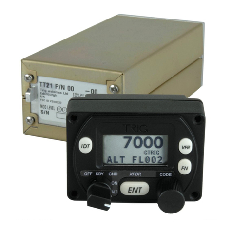
TT21/TT22 Mode S Transponder
Installation Manual
00560-00-AP
22 August 2017
Trig Avionics Limited
Heriot Watt Research Park
Riccarton, Edinburgh
EH14 4AP
Scotland, UK
Copyright Trig Avionics Limited, 2013

This page intentionally left blank

TT21/TT22 Transponder Installation Manual 22 August 2017
00560-00 Issue AP
______________________
Trig Avionics Limited i
CONTENTS
1. PREFACE...............................................................................................1
1.1 PURPOSE...........................................................................................1
1.2 SCOPE...............................................................................................1
1.3 CHANGES FROM PREVIOUS ISSUE......................................................1
1.4 DOCUMENT CROSS-REFERENCES......................................................2
2. INTRODUCTION..................................................................................3
2.1 TT21/TT22 DESCRIPTION.................................................................3
2.2 INTERFACES......................................................................................3
2.2.1 TT21/TT22 Transponder Unit..................................................3
2.2.2 TC20 Controller Unit...............................................................4
3. TECHNICAL SPECIFICATIONS.......................................................5
3.1 TT21 TRANSPONDER UNIT (00675-00-01).......................................5
3.2 TT22 TRANSPONDER UNIT (00745-00-01).......................................6
3.3 TC20 CONTROL UNIT (00649-00).....................................................7
3.4 INSTALLATION APPROVAL.................................................................8
4. UNIT AND ACCESSORIES SUPPLIED.............................................9
4.1 TT21 MODE STRANSPONDER ITEMS................................................9
4.2 TT22 MODE STRANSPONDER ITEMS................................................9
4.3 TC20 CONTROLLER ITEMS................................................................9
4.4 INSTALLATION KIT............................................................................9
4.5 REQUIRED ITEMS ............................................................................10
5. INSTALLATION.................................................................................12

TT21/TT22 Transponder Installation Manual 22 August 2017
00560-00 AP
______________________
ii Trig Avionics Limited
5.1 UNPACKING AND INSPECTING EQUIPMENT......................................12
5.2 CONTROLLER MOUNTING................................................................12
5.3 TRANSPONDER MAIN UNIT MOUNTING...........................................13
5.4 COOLING REQUIREMENTS ...............................................................13
5.5 TT21/TT22 TRANSPONDER ELECTRICAL CONNECTIONS................14
5.5.1 TT21/TT22 Interface –Pinout................................................14
5.6 TT21/TT22 TRANSPONDER INTERFACE DETAILS ...........................15
5.6.1 Power Input............................................................................15
5.6.2 TMAP Bus ..............................................................................16
5.6.3 Power On ...............................................................................16
5.6.4 Controller Power ...................................................................16
5.6.5 Mutual Suppression................................................................16
5.6.6 Ident Switch Input ..................................................................17
5.6.7 Squat Switch Input .................................................................17
5.6.8 External Standby Input...........................................................17
5.6.9 GPS Position Input.................................................................17
5.6.10 TIS Traffic Output ..................................................................18
5.7 TC20 CONTROLLER ELECTRICAL CONNECTIONS ............................18
5.7.1 TC20 Interface - Pinout .........................................................19
5.8 TC20 CONTROLLER INTERFACE DETAILS .......................................19
5.8.1 TMAP Bus ..............................................................................19
5.8.2 Altitude Out............................................................................20
5.8.3 Remote ON.............................................................................20
5.8.4 Power.....................................................................................20

TT21/TT22 Transponder Installation Manual 22 August 2017
00560-00 Issue AP
______________________
Trig Avionics Limited iii
5.9 DCONNECTOR CRIMP TERMINALS .................................................20
5.10 WIRING CONSIDERATIONS...............................................................21
5.11 ANTENNA INSTALLATION................................................................22
5.11.1 Antenna Ground Plane...........................................................23
5.11.2 Antenna Cable........................................................................24
5.11.3 TNC Connector ......................................................................26
5.12 STATIC PRESSURE CONNECTION .....................................................27
6. INSTALLATION SETUP AND TEST...............................................29
6.1 CONFIGURATION ITEMS...................................................................29
6.1.1 VFR Flight ID ........................................................................29
6.1.2 Aircraft Address Programming..............................................30
6.1.3 VFR Squawk Code .................................................................30
6.1.4 Airspeed Category..................................................................30
6.1.5 Aircraft Category...................................................................31
6.1.6 Squat Switch Source...............................................................31
6.1.7 TIS Output..............................................................................31
6.1.8 GPS Input...............................................................................31
6.1.9 GPS/TIS Line Speed...............................................................31
6.1.10 GPS Certification Level .........................................................32
6.1.11 GPS NAC velocity ..................................................................32
6.1.12 Aircraft Length and Width .....................................................32
6.1.13 GPS Antenna Offset ...............................................................33
6.1.14 1090 MHz Receiver Installed.................................................33
6.1.15 UAT Receiver Installed ..........................................................33

TT21/TT22 Transponder Installation Manual 22 August 2017
00560-00 AP
______________________
iv Trig Avionics Limited
6.2 TEST AND CALIBRATION ITEMS.......................................................34
6.2.1 Voltage Check ........................................................................34
6.2.2 Altitude Encoder Calibration.................................................34
7. POST INSTALLATION CHECKS....................................................38
8. NORMAL OPERATION ....................................................................39
8.1 OVERVIEW......................................................................................39
8.2 DISPLAY..........................................................................................39
8.3 MODE SELECTOR KNOB..................................................................40
8.4 PUSH BUTTONS...............................................................................40
8.5 CODE SELECTOR KNOB...................................................................41
8.6 ALTITUDE ENCODER WARM UP......................................................41
8.7 GENERAL LOW TEMPERATURE OPERATION....................................41
8.8 ADS-B MONITOR ...........................................................................42
8.9 DISPLAY BRIGHTNESS CONTROL.....................................................42
8.10 WARNING MESSAGES......................................................................42
8.11 FAULT ANNUNCIATION ...................................................................42
9. CONTINUED AIRWORTHINESS....................................................44
10. LIMITED WARRANTY.................................................................45
11. ENVIRONMENTAL QUALIFICATION FORMS ......................46
12. ADS-B COMPLIANCE...................................................................52
12.1 ADS-B PARAMETERS SUPPORTED..................................................52
12.2 FAA 91.227 COMPLIANCE..............................................................53

TT21/TT22 Transponder Installation Manual 22 August 2017
00560-00 Issue AP
______________________
Trig Avionics Limited v
12.3 CS-ACNS COMPLIANCE .................................................................54
12.4 TSO C199 TABS COMPLIANCE......................................................55
12.5 AUTOMATIC AIR/GROUND DETERMINATION...................................55
12.6 ADS-B SUPPORT ............................................................................55
13. INSTALLATION DRAWINGS......................................................56
13.1 MOUNTING TRAY FIXING AND OVERALL DIMENSIONS......................56
13.2 FRONT PANEL CONTROLLER DIMENSIONS ......................................57
13.3 FRONT PANEL CUT-OUT OPTIONS ...................................................58
14. BASIC INTERCONNECT DIAGRAM .........................................60

TT21/TT22 Transponder Installation Manual 22 August 2017
00560-00 AP
______________________
vi Trig Avionics Limited
This page intentionally left blank

TT21/TT22 Transponder Installation Manual 22 August 2017
00560-00 Issue AP
______________________
Trig Avionics Limited 1
1. Preface
1.1 Purpose
This manual describes the physical and electrical characteristics and the
installation requirements for a TT21/TT22 Mode S Transponder and
associated TC20 controller.
1.2 Scope
This document applies to the installation of the TT21 or TT22 Mode S
Transponder.
At the publication date of this manual the software version identifier for the
TT21 and TT22 is 2.12 and the FPGA version identifier is 1.2. The TC20
controller software version identifier is 1.14. The software and FPGA versions
are subject to change without notice.
1.3 Changes from Previous Issue
Changes from Issue AO to Issue AP are:
5.6.7 Squat Switch Input
Addition of note about GPS air/ground
determination.
5.6.9 GPS Position Input
Addition of Trig TN72 GPS.
6.1.9 GPS Line Speed
Addition of TN72 at 9600 bps.
8.3 Mode Selector
Minor editorial change.
12.2 FAA 91.227 Compliance
Reformatted, added Trig TN72.
12.3 CS-ACNS Compliance
Reformatted.
12.5 Automatic Air/Ground
Added GPS air/ground determination.

TT21/TT22 Transponder Installation Manual 22 August 2017
00560-00 AP
______________________
2 Trig Avionics Limited
1.4 Document Cross-References
00559-00
TT21 Mode S Transponder Operating Manual
AF

TT21/TT22 Transponder Installation Manual 22 August 2017
00560-00 Issue AP
______________________
Trig Avionics Limited 3
2. Introduction
2.1 TT21/TT22 Description
The TT21/TT22 Mode S transponder system is an ED-73C compliant Mode S
level 2els datalink transponder, with support for ADS-B extended squitter,
elementary surveillance and SI codes, which also meets the relevant
environmental requirements of ED-14F. The TT21 has a nominal power
output of 125 Watts, and meets the power output requirements for Class 2.
The TT22 has a nominal power output of 250 watts, and meets the power
output requirements for Class 1. The ADS-B function meets DO-260B class
B0 for the TT21 and class B1S for the TT22. The TT21/TT22 is certified to
ETSO 2C112b and ETSO C166a, and to FAA TSO C112c and C166b.
The TT21/TT22 transponder is controlled using a separate front panel
controller, called the TC20. This allows the transponder to be mounted
separately from the instrument panel, and reduces the amount of panel space
taken by the transponder. The TC20 includes an altitude encoder. The TC20
is certified to ETSO 2C112b and ETSO C88a, and to FAA TSO C112c and
TSO C88b.
The TT21/TT22 transponder runs from either 14 volt nominal or 28 volt
nominal DC power supply with no configuration changes required.
The TT21/TT22 transponder responds to both legacy Mode A/C interrogations
and to Mode S interrogations from both ground radar and airborne collision
avoidance systems. In all cases, the interrogations are received by the
transponder on 1030MHz, and replies are transmitted on 1090MHz.
2.2 Interfaces
2.2.1 TT21/TT22 Transponder Unit
The main transponder unit has a single TNC antenna connection and a single
25 way D-type connector. The 25 way D-type interface provides the following
services:

TT21/TT22 Transponder Installation Manual 22 August 2017
00560-00 AP
______________________
4 Trig Avionics Limited
Power Input
The TT21/TT22 operates on 11 to 33 Volts DC.
Front Panel Datalink
A two wire data link is used to connect the TT21/TT22
and the controller.
Front Panel Power
The controller is powered from the transponder.
Remote On/Off
The on-off switching is on the controller, and switches this
input.
Ident input
External IDENT switch input.
Standby input
External standby input for dual transponder installations.
“On ground” input
Allows automatic flight/ground mode switching for
aircraft with a squat switch.
Suppression bus I/O
ARINC compatible suppression bus signal used in aircraft
with other pulse equipment, such as DME. This pin is
both an input to and output from the transponder.
GPS Input
Connection to a GPS supplying position input for ADS-B
position reporting.
TIS Output
Connection to a traffic display.
2.2.2 TC20 Controller Unit
The TC20 controller has a single 9 way D-type connector. It provides the
following services:
Power Input
The controller receives power from the transponder.
Front Panel Datalink
A two wire data link is used to connect the
TT21/TT22 and the controller.
Remote On/Off
The on-off switching is on the controller, and controls
this output.
Altitude Output
An additional serial output on the TC20 provides
pressure altitude information that can be used for baro-
aiding by certain GPS receivers.

TT21/TT22 Transponder Installation Manual 22 August 2017
00560-00 Issue AP
______________________
Trig Avionics Limited 5
3. Technical Specifications
3.1 TT21 Transponder Unit (00675-00-01)
Specification
Characteristics
Compliance
ETSO 2C112b Class 2 Level 2els, ETSO
C166a Class B0, TSO C112c Class 2 Level
2els, TSO C166b Class B0
FCC Identification
VZI00675
Applicable documents
EUROCAE ED-73C, EUROCAE ED-14F
(RTCA DO-160F), RTCA DO-181D, RTCA
DO-260B
Software
ED-12B (RTCA DO-178B) Level B
Hardware
DO-254 Level C
Power Requirements
11 –33 Volts DC. Typical 5 Watts @ 14Volts.
Altitude
35,000 feet
Humidity
95% @ +50°C for 6 hours; 85% @ +38°C for
16 hours.
Tested to Category A in DO-160F
Operating Temperature
-20°C to +70°C
Transmitter Frequency
1090MHz ± 1MHz
Transmitter Power
125 Watts nominal; 71 Watts minimum at
antenna after allowing for 0.5dB connector
losses and 1.5dB cable losses.
Transmitter Modulation
6M75 V1D
Receiver Frequency
1030 MHz
Receiver Sensitivity
-74dBm ± 3dB

TT21/TT22 Transponder Installation Manual 22 August 2017
00560-00 AP
______________________
6 Trig Avionics Limited
Physical Specifications (in the mounting tray)
Height
48mm (1.9”)
Width
66mm (2.5”)
Length
160mm (6.3”)
Weight
0.77lbs. (350 g)
3.2 TT22 Transponder Unit (00745-00-01)
Specification
Characteristics
Compliance
ETSO 2C112b Class 1 Level 2els, ETSO
C166a Class B0, TSO C112c Class 1 Level
2els, TSO C166b Class B1S
FCC Identification
VZI00745
Applicable documents
EUROCAE ED-73C, EUROCAE ED-14F
(RTCA DO-160F), RTCA DO-181D, RTCA
DO-260B
Software
ED-12B (RTCA DO-178B) Level B
Hardware
DO-254 Level C
Power Requirements
11 –33 Volts DC. Typical 6 Watts @ 14Volts.
Altitude
35,000 feet
Humidity
Tested to Category A in DO-160F
Operating Temperature
-20°C to +70°C
Transmitter Frequency
1090MHz ± 1MHz
Transmitter Power
250 Watts nominal; 125 Watts minimum at
antenna after allowing for 0.5dB connector
losses and 1.5dB cable losses.
Transmitter Modulation
6M75 V1D

TT21/TT22 Transponder Installation Manual 22 August 2017
00560-00 Issue AP
______________________
Trig Avionics Limited 7
Receiver Frequency
1030 MHz
Receiver Sensitivity
-74dBm ± 3dB
Physical Specifications (in the mounting tray)
Height
48mm (1.9”)
Width
66mm (2.5”)
Length
160mm (6.3”)
Weight
0.77lbs. (350 g)
3.3 TC20 Control Unit (00649-00)
Specification
Characteristics
Compliance
ETSO 2C112b, ETSO C88a, TSO C112c, TSO
C88b
Applicable documents
EUROCAE ED-73B, EUROCAE ED-14F (RTCA
DO-160F), RTCA DO-181D, SAE 8003
Software
ED-12B (RTCA DO-178B) Level B
Altitude
-1000 to 35,000 feet
Humidity
95% @ +50°C for 6 hours; 85% @ +38°C for 16
hours. Tested to Category A in DO-160F
Operating Temperature
-20°C to +55°C
Physical Specifications (behind the panel)
Height
44mm (1.8”)
Width
63mm (2.4”)
Length
54mm (2.1”)
Weight
0.11lbs. (90 g)

TT21/TT22 Transponder Installation Manual 22 August 2017
00560-00 AP
______________________
8 Trig Avionics Limited
3.4 Installation Approval
The conditions and tests required for the TSO approval of the TT21/TT22
Mode S Transponder are minimum performance standards. It is the
responsibility of those desiring to install this transponder on or within a
specific type or class of aircraft to determine that the aircraft operating
conditions are within the TSO standards. The transponder may be installed
only if further evaluation by the user/installer documents an acceptable
installation that is approved by the appropriate airworthiness authority.

TT21/TT22 Transponder Installation Manual 22 August 2017
00560-00 Issue AP
______________________
Trig Avionics Limited 9
4. Unit and Accessories supplied
4.1 TT21 Mode S Transponder Items
The TT21 Mode S transponder includes the following items:

Unit Description
Qty
Part Number
TT21 Mode S Transponder
1
00675-00-01
TT21/TT22 Mounting Tray
1
00667-00
4.2 TT22 Mode S Transponder Items
The TT22 Mode S transponder includes the following items:
Unit Description
Qty
Part Number
TT22 Mode S Transponder
1
00745-00-01
TT21/TT22 Mounting Tray
1
00667-00
4.3 TC20 Controller Items
The TC20 controller includes the following items:
Unit Description
Qty
Part Number
TC20 Transponder Controller
1
00649-00
TT21/TT22 Installation Kit
1
00668-00
4.4 Installation Kit
The TT21/TT22 installation kit includes the following items:

TT21/TT22 Transponder Installation Manual 22 August 2017
00560-00 AP
______________________
10 Trig Avionics Limited
Unit Description
Qty
Part Number
TT21/TT22 Transponder Installation
Manual
1
00560-00
TT21/TT22 Pilots Operating Manual
1
00559-00
Mounting adapter (circular hole adapter)
2
00678-00
Connector Co-axial TNC
1
00723-00
Headshell, 9 Way
1
00725-00
Headshell, 25 way
1
00726-00
9 way D-type contact housing (female)
1
00727-00
25 way D-type contact housing (male)
1
00728-00
Crimp Terminal, Male, 22-24 AWG
20
00729-00
Crimp Terminal, Female, 22-24 AWG
9
00730-00
Static tubing, EPDM 5mm ID
1
00731-00
Hose T piece
1
00732-00
Hose Adapter
2
00733-00
Hose clip, small
6
00734-00
Hose clip, large
2
00735-00
Long mounting screws, 4-40 thread
4
00736-00
Short mounting screws, 4-40 thread
4
00737-00
4.5 Required Items
Additional items you will require, but which are not in the TT21/TT22
package, include:
Antenna and fixing hardware. The TT21/TT22 is compatible with
any transponder antenna approved to ETSO C74 or 2C112 or

TT21/TT22 Transponder Installation Manual 22 August 2017
00560-00 Issue AP
______________________
Trig Avionics Limited 11
equivalent.
Cables. You need to supply and fabricate all required cables.
Guidance on cable types is given in section 5 below.
Fixings. To secure the transponder tray to the airframe you will need
at least 3 flat head screws and three self-locking nuts. If the aircraft
does not have existing mounting provisions you may need to fabricate
additional brackets to support the transponder tray.
To support the optional ADS-B features a GPS receiver with an appropriate
serial output is required. To support the optional TIS features a display with an
appropriate serial input is required.

TT21/TT22 Transponder Installation Manual 22 August 2017
00560-00 AP
______________________
12 Trig Avionics Limited
5. Installation
5.1 Unpacking and Inspecting Equipment
Carefully unpack the transponder and make a visual inspection of the unit for
evidence of any damage incurred during shipment. If the unit is damaged,
notify the shipping company to file a claim for the damage. To justify your
claim, save the original shipping container and all packaging materials.
5.2 Controller Mounting
The TC20 transponder controller must be mounted rigidly in the aircraft panel.
The controller can be mounted in the ultra compact mounting hole or in a
conventional 57mm (2¼ inch) instrument cut-out.
The following installation procedure should be followed, remembering to allow
adequate space for installation of cables and connectors.
Select a position in the panel that is not too close to any high external
heat source. (The TC20 is not a significant heat source itself and
does not need to be kept away from other devices for this reason).
Avoid sharp bends and placing the cables too near to the aircraft
control cables.
If you are using a 57mm instrument cut-out, you must first clip the two
mounting adapters to the transponder. The controller should then be mounted
using the four LONG screws provided.
Note: The mounting adapters are held in place by the clamping
action of the panel installation. As an aid to securing them during
assembly when access is poor, we recommend putting a rubber band
around the adapters and the control head. The rubber band can be
snipped off and discarded when the installation is complete.
If you are using the Trig compact cut-out, you do not need the mounting
adapters. The controller should be mounted using the four SHORT screws
provided. The screws supplied are appropriate for panel thicknesses from 3
Other manuals for TT21
2
This manual suits for next models
1
Table of contents
Other trig Marine Radio manuals