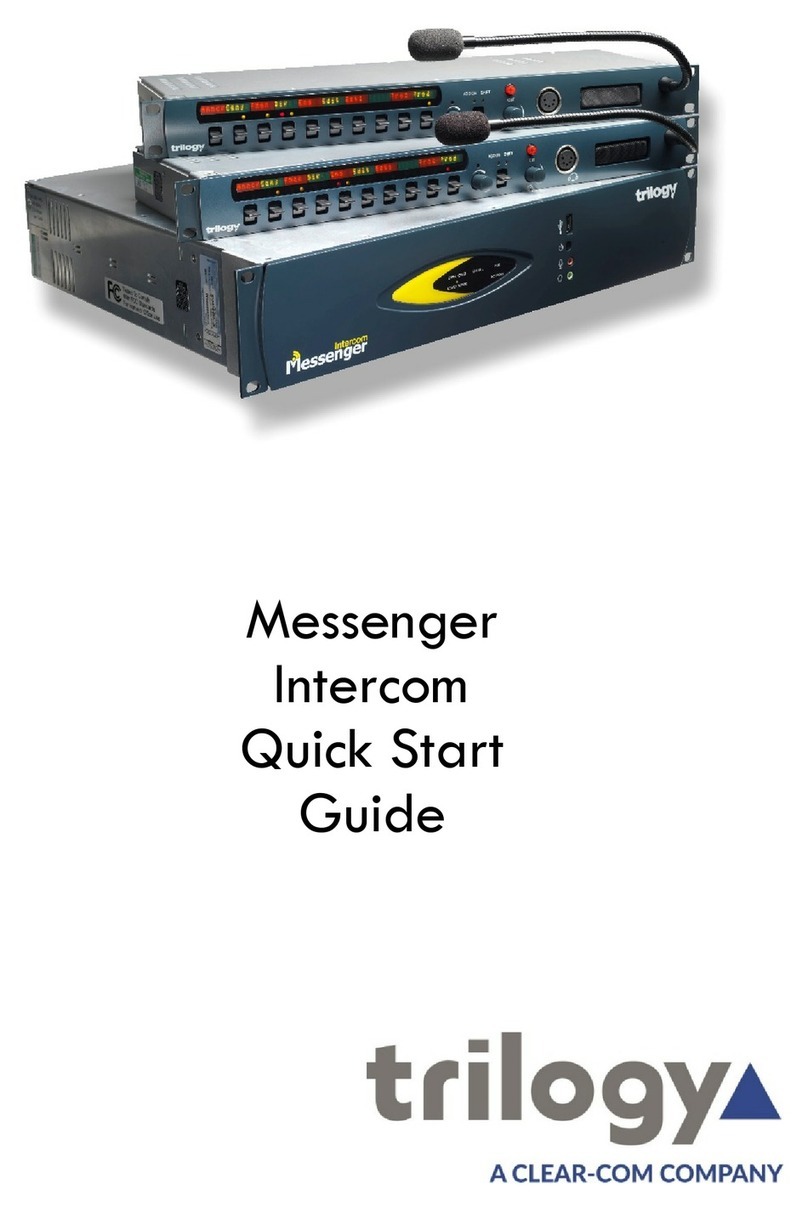
Trilogy Communications Gemini User manual

Short Form User Guide
ISSUE 0.60
TRILOGY COMMUNICATIONS LIMITED
26 Focus Way
Andover
Hampshire
SP10 5NY
United Kingdom
Telephone: +44 (0) 1264 384000
Fax: +44 (0) 1264 334806
www.trilogycomms.com

Short Form User Guide
Page 2 of 60 Trilogy Communications
The Copyright of the information and drawings in this document is
the property of Trilogy Communications Limited of Andover,
Hampshire and is neither to be reproduced in whole or in part, nor
disclosed to a third party, without the prior written consent of Trilogy
Communications Limited.
The information in this document has been carefully compiled and
checked for accuracy. However, Trilogy Communications Limited
accepts no responsibility for inaccuracies which may occur and,
further, reserves the right to make changes to specification or design
without prior notice.
Comments or correspondence concerning this manual should be
addressed to the Publications Manager at the address given at the
front of this User Guide.
DOCUMENT NUMBER 70090622.docx ISSUE 0.60
Issue
Date
Reason for Change
Approved
0.35
17 June 2011
Corrected typos
0.40
17 January 2012
Roles and Administrators
0.45
24 January 2012
Non-disruptive changes
0.50
30 January 2012
Updated screen grabs
0.60
14 May 2014
Password change

Short Form User Guide
Page 3 of 60 Trilogy Communications
Introduction........................................................... 5
Before You Start ................................................ 5
Getting Started ...................................................... 6
Gemini Matrix.................................................... 6
Introduction to Gateway, the System Configuration
Editor ..................................................................... 8
Gateway Operational Methodology .................. 9
Tutorial 1: Configuring a Simple System.............. 11
Configuration – First Steps .............................. 12
Enterprise Editor.............................................. 12
Domain Editor.................................................. 12
Subscribers ...................................................... 14
Panel Editor ..................................................... 15
Upload and Restart the Configuration............. 18
Control Panels...................................................... 19
Panel Keys and Tallies...................................... 19
The Panel Display............................................. 20
Shift Mode ....................................................... 20
Loudspeaker Volume ....................................... 20
Rotary Encoders (RENs) ................................... 20
Assignable Features......................................... 21
‘Cut’ Switch Features ....................................... 22
Extra Panel Features........................................ 22
Tutorial Two – Understanding More Complex
Functions ............................................................. 23
Before You Start .............................................. 23
Permanent Crosspoints, or “Fixed Routes” ..... 23
Groups ............................................................. 24
Conferences, and Production Talkback ........... 26
.Production Talkback Conference – Operation
..................................................................... 27
IFBs .................................................................. 29
What Does This All Mean?........................... 31
Dimming .......................................................... 32
Mirror Dimming ........................................... 32
Dimming Locations ...................................... 32
Configuring a System with more than one Matrix34
Before You Start ............................................... 34
Introduction to Systems With More Than One
Gemini Matrix .................................................. 34
High Speed Link (HSL)................................... 34
Network ....................................................... 34
Tutorial 3 –Creating a Gemini Ring .................. 35
Configuration Changes..................................... 36
Configuring a Multi-site System........................... 37
Before You Start............................................... 37
Introduction to Systems Operating over Multiple
Sites.................................................................. 37
High Speed Link (HSL)................................... 37
Network ....................................................... 38
Network Audio ............................................. 38
Gateways and Routers ................................. 39
Tutorial 4 –Gemini Systems on Two Domains.. 39
Configuration Changes................................. 40
Configuring a Gemini System for multiple
administrators...................................................... 41
Introduction ..................................................... 41
Launching the Roles and Administrators Editor
......................................................................... 41
Creating Roles .................................................. 41
Creating Administrators................................... 43
Associating Roles and Administrators.............. 44
Non-Disruptive Changes ...................................... 45
Introduction ..................................................... 45
Making changes ............................................... 45

Short Form User Guide
Page 4 of 60 Trilogy Communications
Appendix 1 – Basic Troubleshooting ................... 47
Appendix 2 – Key Types....................................... 48
Appendix 3 - Interfacing to Mercury ................... 49
Interfacing to Mercury Hosts........................... 49
Appendix 4 – Soft Panels ..................................... 50
Virtual Panels................................................... 50
Patch Panels..................................................... 51
Appendix 5 - POTS Telephony.............................. 52
Appendix 6 - Commander/Orator........................ 54
Appendix 7 – A Basic Introduction to GPIO ......... 56
GPI -> Route..................................................... 58
Route->GPO ..................................................... 58
Route->Route................................................... 58
Appendix 8 – Introduction to SIP......................... 59
Appendix 9 – Comparison of Control Panel
Facilities ............................................................... 60

Short Form User Guide
Page 5 of 60 Trilogy Communications
Introduction
Gemini is a flexible intercom system, built on the
concept of a de-centralised, scalable platform of
32 port matrices, each with IP connectivity. The 20
kHz audio performance is preserved both
internally and over a Gemini network of up to 256
ports using a proprietary High Speed Link (HSL)
using standard Cat 5 or fibre-optic connections.
This approach eliminates the single point of failure
associated with a traditional large matrix system,
and the use of a dual redundant ring of audio and
IP failsafe routing, ensures that Gemini delivers
ultra-resilient performance.
Gemini’s flexible design is suited to every
application ranging from small single studios to the
largest multi-studio complex. Using Gemini’s
seamless IP interfacing, a network can be
expanded almost limitlessly both in terms of
system size and geographic location via LAN, WAN
or Satellite. Connectivity for both traditional and IP
enabled intercom panels is provided, together
with support for telephony, with intelligent
interfacing to analogue and SIP enabled phone
systems, as well as portable devices.
This document is provided to guide the system
administrator through the configuration of typical
systems, starting with a simple single-matrix
system and culminating in a multi-matrix, multi-
site distributed system using IP connectivity.
Appendices are provided covering more advanced,
but less commonly used functionality.
Before You Start
This guide assumes that the Gemini system,
including any control panels, has been installed
correctly, and that the Gateway configuration and
database software is installed. The PC or laptop
that has the Gateway software, and the Gemini
matrix, should be connected to an IP Network.
Ports 1 - 32
High Speed Link +
High Speed Link -
LAN
GPI
Fault Loop Alarm
Commander/Orator Networking
Camera Mix/DA
Aux – Beltpack DC Power
32 IP Channels
Gateway
Configuration Editor
It may be useful to refer to other Gemini documentation
for more detailed information on the topics covered in
this guide.
Gemini Implementation Guide (document
70090620)
Gateway Configuration Guide (document
70090621)
These documents are available on the product CD
shipped with your system, or directly from Trilogy.
The Gemini Matrix
Refer to the Gemini Implementation Guide.

Short Form User Guide
Page 6 of 60 Trilogy Communications
Getting Started
Gemini Matrix
Apply power to your Gemini Matrix. It will take a
short while to boot up and will then show the main
menu.
The front panel display is equipped with a touchscreen,
so no keyboard or mouse is required to configure the
unit.
Press the SETTINGS button, followed by the SETUP
button and check the IP Address, Subnet Mask and
Database Server IP address have been configured.
Now launch a web browser programme on a PC
connected to the same network as the Gemini matrix,
and with an IP address in the same subnet – it might be
most convenient to use the PC that runs the Gateway
configurations software.
Type the IP address of the Gemini Matrix in the address
bar and, if all the IP addresses have been entered
correctly, a status page will be displayed.
“BACK” button. Returns to previous
menu.
“HOME” button. Returns to top menu.
STATUS menu. Allows the status of the
software, power supplies, fan, LAN and
HSL connections to be checked, and
software revisions to be reported.
TOOLS menu. Audio monitoring, GPI
testing and monitoring, panel status and
route information. Also allows the system
to be reset.
SETTINGS menu. Setup of IP addresses,
“EDH” address and keypad click on/off.
INFO menu. Shows which option modules
are fitted, as well as basic wiring
information for the rear panel connectors.
The name assigned to this Gemini matrix
The IP address of the matrix must be in the
same range – or subnet – as that of the PC
running the Gateway Software. For example,
the PC might have IP address 192.168.10.10
(subnet mask 255.255.255.0) and the matrix
perhaps 192.168.10.100. G
iven those IP
addresses, the Gemini matrix would have the
Database Server IP address set to match that of
the PC.
The addresses should have been configured
during system installation. Refer to the Gemini
Implementation Guide.
Status and Alarm Indicator

Short Form User Guide
Page 7 of 60 Trilogy Communications
At this point, take time to explore the various tabs
presented on the status screens, but do not be
concerned about any error messages at this time.
It is recommended not to make any changes yet.
The pages refresh automatically approximately
every 10 seconds.
It is worth checking that the Gemini matrix is
reporting an “EDHS” address of 0.1.1 (EDHS, and
the relevance of this, will be explained later).
The default password for both the “admin” and
“debug” Settings pages is:
trilogy
At this point, the Gemini System is installed, connected and operational. Should it NOT be
operational, a short troubleshooting guide is available as Appendix 1.

Short Form User Guide
Page 8 of 60 Trilogy Communications
Introduction to Gateway, the System Configuration Editor
Gateway is the software application used to configure the Gemini system.
A “configuration” is all of the information needed for the matrix system to operate as required: IP addresses so
they can communicate; declarations of the panels and other audio devices that are connected; what the panel
keys should do; groups and conference functionality; and so on.
The configuration is stored in a set of database tables on a PC acting as a server. This database server may be
the same one as that on which the Gateway editor is run, but it need not be.
The database is of a client/server design and is managed by a Windows service named “Trilogy Database
Supervisor”. This service is loaded automatically every time the PC starts up, and it then runs in the
background.
The client/server design means that multiple “clients” can connect simultaneously while the supervisor
manages the reading and submission of data to and from the database, and provides file “locking” to prevent
two clients attempting to change data at the same time.
In the context of Gemini, “clients” include the Gemini configuration editor itself as well as the Gemini matrices
and any soft panels in use.
The Gateway Editor and Database Supervisor should already have been installed on a PC or laptop that is
connected to the same network as the Gemini Matrix.
A small graphical application is also provided as
part of the installation. This allows you to monitor
the current status of the database and to perform
routine maintenance and troubleshooting. It will
launch automatically at start up. When it is run, a
small additional icon will be displayed in the
Windows system tray adjacent to the clock. On
double clicking the icon, the database supervisor
will be displayed.
This applications is available via the Start Menu
and is called “DatabaseSupervisorGui.exe”
Start up the Gateway Editor on the PC.
If all is well, the Database Supervisor should now
show that both the Gateway Editor and the Gemini
Matrix are connected and operational.
A similar form is available by clicking the “Active
Clients” button in the main Gateway editor
window – this is described in Tutorial 1, as part of
uploading and restarting the system to run a new
configuration.
DB Supervisor icon
The default top level Administrator is:
Admin
The default password is:
trilogy

Short Form User Guide
Page 9 of 60 Trilogy Communications
Gateway Operational Methodology
Gateway has a number of principle areas within the main application window
The tree view list in the left hand pane is the main
navigational tool within Gateway.
Where an entry has an arrow next to it, the tree
may be expanded to show “children” of the
parent.
To access a basic editor, single click on the
required item. For example, to edit “Host 1.1”
simply click once on the “Host 1.1” symbol in the
tree view.
To access an advanced editor, double click on the
symbol as appropriate
The selected editor will then appear in the Main
Window to the right.
“MENU” button. Accesses all
menus such as “FILE” and “TOOLS”
Name of the current configuration,
and configuration version number
A tree view list
of configured
functionality and
devices, and
quick access to
the main
Gateway editor
tools.
Main Editor window.
“Standard” editors cover the majority of day-to-day
activities for a system that is already configured and running
“Advanced
” editors are needed during initial system
configuration and, later, for some more complex functions.
Click to launch the “Active Clients”
window to connect to Gemini
system. The colour shows if the on-
screen configuration has changed.
GREEN in sync
RED - out of sync

Short Form User Guide
Page 10 of 60 Trilogy Communications
Once an editor is selected, a variety of editing
methods are supported, depending on the activity
being undertaken such as: drop-down selection
boxes; “either/or” selection (or “radio” buttons);
text entry; or drag-and-drop. These will be
explained as necessary in the later section
describing the configuration of a simple Gemini
system. You can also right-click within many forms
to call up a selection list.
Many editors have navigation buttons allowing
quick access to the next “record” (for example, the
next panel connected to the host). This tool bar
also has “accept” and “reject” change buttons –
note that any changes made are automatically
accepted when you move on to edit something
else, so if you want to reject a change made, you
must click on the reject cross. A “refresh data”
button at the end reloads the information stored
in the database for that editor page should there
be any doubt as to whether the page is current or
not.
It is also useful to know that every menu item or
button has a “tool tip”: if the mouse cursor is
allowed to hover over a button, a brief explanation
will appear.
Many editors also have “add” and “delete”
buttons allowing, for example, an entire Gemini
matrix unit to be added or deleted from the
configuration. This tool bar also has a “grid
options” button that allows, for example,
displayed data to be exported (for documentation
purposes, for example)
An example of “radio buttons”
A “tool tip” showing that the
circular arrow means “Refresh
Data”

Short Form User Guide
Page 11 of 60 Trilogy Communications
Tutorial 1: Configuring a Simple
System
This tutorial will walk through the initial
configuration of a simple Gemini system.
It is recommended that you read all the preceding
chapters first, to ensure you are familiar with the
basic operational philosophy of the Gateway
configuration editor, as well as making sure your
Gemini matrix is operational, and that both are
succesfully connected to the database supervisor.
A “Simple” system, or enterprise, for the purposes
of this guide, means:
A single Gemini matrix, or host in a single
domain
No HSL audio connections
No use of IP audio
The tutorial will walk through the creation of a
completely new configuration from scratch,
including the addition and configuration of control
panels and 4-wire ports – subscribers - and then
we will upload the configuration to the matrix,
restart the configuration on the system, and check
that everything is working correctly.
Further sections in this guide explain control
panels themselves covering:
Key Operation
Tallies
“cut” switch functionality
The rotary encoder control, or “REN”
There are also more advanced tutorials explaining
Fixed Crosspoints
Groups
Conferences and Production Talkback
IFBs
Dimming.
Enterprise; Domain; Host; Subscriber –
what’s that all about?
Since a Gemini system can comprise many
elements –
individual Gemini matrices,
perhaps installed over several sites, with a
large
number of control panels and other
audio devices – with the added complexity of
an IP network,, as well as the High Speed
Link, it is necessary to have a numbering
system within Gemini that uniquely identifies
all these elements.
The system employed is kn
own as the
“e.d.h.s” system:
e=enterprise and is used to represent the
complete system. At present “e” is
always 0, but the adoption of “e” allows
for future expansion to assist
interoperability between completely
different broadcasters, for example.
d=domain
. A domain is a convenient
collection of devices, usually in the same
physical location, such as “studio 1”.
They can be used to logically separate
devices for convenience, but are also
essential when it comes to IP networks:
this will be explained later
h=host
where a host is an individual
Gemini matrix (or a Mercury device such
as an “MIU”)
s=subscriber
which, like a telephone
subscriber, is at the end of the line – the
actual device used by the operator, such
as a control panel, or an audio port.

Short Form User Guide
Page 12 of 60 Trilogy Communications
The Advanced Host Editor can also be
used to mark the host as “offline” –
useful if a host will be added later, to
avoid error messages in the meantime.
Configuration – First Steps
Start the Gateway configuration editor.
To be sure we’re working with a new, blank
configuration, click the menu button and select
the File menu and the choose New (refer to the
section entitled “Gateway Operational
Methodology” if you’re not sure where the menu
button is.
Click Yes when asked if you’re sure you want to
create a new configuration – although if another
administrator has been working on a configuration
is might be worth saving their work first – this can
be done from the same File menu by choosing
Save.
Enterprise Editor
Now single click the very top entry in the tree view
(in the left hand pane of the editor) – it will be
labelled Config<date> where <date> is today’s
date. This opens up the Enterprise Editor, and we
can give our new configuration a name – for
example “Tutorial 1” and perhaps the description
could be “Simple Gemini system configuration “.
No other changes are needed at the Enterprise
level.
Domain Editor
Next, expand the tree view relating to Domains by
clicking the arrow to the left, to reveal that the
configuration has, by default, created a single
domain called “Domain1. Expand the tree
associated with Domain1 - the default
configuration also includes 2 Gemini hosts – Host
1.1 and Host 1.2.
Single click on the Domain 1 element of the tree
view to open the Domain editor.
Since this configuration only requires a single
Gemini mattrix, Host 1.2 can be deleted if required
by selecting the row it is shown on and clicking the
“minus” button, which looks like this

Short Form User Guide
Page 13 of 60 Trilogy Communications
USEFUL TIP
When you have entered the first
“octet” (192 in this example) you can
move to the next field (where we’ll
enter 168 in this example) by
Either pressing the tab key on the
keyboard
or, since this is an IP address that
is separated by a a dot (or “full
stop”, or a “period”), you can
press the “dot” key on the
keyboard
Port is the term used to describe the
physical connection on the back of the
Gemini matrix to which a panel, for
example, is connected.
Host 1.1 (the 1.1 means domain 1, host 1, as
determined by the e.d.h.s numbering scheme),
can be renamed if wished by clicking the name
field associated with this host and entering your
own name – perhaps “Gemini Matrix1” – along
with a comment if so required.
The most important field to configure is the IP
address. Without this being entered, the database
supervisor will not be able to locate the correct
Gemini matrix on the IP network.
The IP address must match the IP address given to
the Gemini we’re configuring – this should have
been noted in the earlier sections. For the
purposes of this document, 192.168.10.100 will be
used
Once the IP address is entered, it is good practice
to click the tick in the navigation tool bar –
although changes will be
saved automatically if you navigate away from this
editor. Once confirmed, the IP address entered will
also appear next to the host in the grid view.
The final step is to make sure that the Gemini
Matrix itself is configured with the correct number
of ports, of the correct type. You will need to refer
to the shipping information or installion records if
you are not sure exactly what your matrix is
equipped with: this tutorial assumes just 8 ports.
Click on the “Type” field, and a list of possible host
types will be presented: select an 8, 16, 24 or 32
port Gemini matrix as appropriate.
You may see a warning that changing the host
type, or number of ports, will require subscribers
to be added or removed – this is OK, so select Yes
to proceed.
The actual port types for the matrix will almost
certainly be correct, the default being “AEB”, or
“Audio Expansion Board”, which support analogue
control panels and 4-wire audio. In the event your
matrix has other modules fitted, please refer to
the full system documentation.
We now need to configure the subscribers to be
the correct type.

Short Form User Guide
Page 14 of 60 Trilogy Communications
TIP: you can resize the width of
columns in the same manner as you
can with spreadsheets –
move the
cursor to
the divider line between
column headings and either drag it to
the required width, or double click it
to automatically resize the column to
a width appropriate to the length of
the text entered.
Subscribers
Single click the host (Gemini Matrix1in this
example) in the tree view to launch the standard
subscriber editor.
Click in the Type field for every port of your matrix
and select the correct type from the drop down
menu, according to your installation.
The two most commonly used port types are Panel
and 4-wire. The different types of panels available,
and their main differences are explained later, and
virtual panels and patch panels are described in
Appendix 4 – Soft Panels.
For each subscriber, a name should be entered.
This name will be used on control panel displays
when keys are assigned to speak or listen to the
subscriber - it is worth bearing in mind that the
majority of trilogy panels support 5 character
labels, so choose appropriate abbrevations
By default, the labels are “H1S1” or similar,
representing “Host 1, Subscriber 1”.
The Long Name is used on panels that support
labels longer than the default 5 characters
It is good practice, although not essential, to enter
a Description for each subscriber – this would
typically be a full explanation of the subscriber
including, perhaps, its location in the studio.
It is not necessary to enter text in the Lstn Label
(the ”Listen” label) field.
For this tutorial, assign the first 4 ports as panels,
and the second as 4-wires, labelling them like this:
The final task, before we have a basic, but
functional, configuration is to add keys to panels.
What is a 4-Wire port?
“4-wire” is the term given to a simple audio
source that has a balanced audio input and
balanced audio output. Balanced audio
requires a pair of wires, each carrying the
audio signal but with opposite polarity – in
electronic terms this means the signal can be
received with minimum chance of electrical
interference. Two pairs –
one pair for the
input and one for the output – results in “4
wires”.
4-wires carry no signalling information: they
are just audio. This means they cannot
inherently cause a tally to illuminate on a
control panel when the 4-wire audio source is
speaking.
However, two basic mechanisms do exist to
allow tallying:
Audio presence detection
General Purpose Input/Outputs, or GPIO
These are briefly described in Appendix 7 – A
Basic Introduction to GPIO.

Short Form User Guide
Page 15 of 60 Trilogy Communications
TIP: if you right-click in the tree view,
menu options allow you to fully
expand, or fully coll
apse, the tree
view.
.
Panel Editor
Ensure the tree view on the left is fully expanded
to show the configured subscribers.
Single click on the first of your panels to launch the
panel editor.
There are a variety of methods provided for the
configuration of panel keys, principally:
Drag and drop within the panel editor
Dialogue box, then selection from lists. This is
selected by clicking within the KEY LABEL area
to cause the “ellipsis” button to be
displayed, then clicking the button to show
the dialogue.
The LABEL of the selected target
Displayed key targets can be “dragged and
dropped” from the Available Targets palette
area to required key location above.
PAGE selection
Bin: drag keys
from the panel to
remove them
from the current
layout.
COPY tools
Choose the type of target currently displayed,
e.g. panels, conferences. Each button has a
tool-tip.
Non-disruptive changes
Navigation tools
Roles and Administrators
File Management
KEY MODE: e.g. speak, listen etc.

Short Form User Guide
Page 16 of 60 Trilogy Communications
To configure panel keys, there are 3 main steps:
1. Choose the KEY TARGET TYPE: panel, 4-
wire, conference etc
2. Choose the actual KEY TARGET (for
example “panel 1” or “4-wire 1)”
3. Choose the key KEY MODE. The most
widely used are the first 4 choices from
the menu, or a “QRS”:
Speak. This key operates as a latching
speak key if you briefly press the key,
otherwise it is a momentary speak,
making a speak route only for the
duration of the keypress. The upwards
and downwards action of a lever-action
key is identical
Latching Speak. This key will always be a
momentary speak if the key is pressed
downwards, and is always latching in the
upwards direction.
Listen. With a latching/momentary
operation the same as the speak key, but
listening rather than speaking. generally
not used for communications with
panels, but useful for 4-wires.
Speak/listen. Has the
latching/momentary characteristics of the
speak key, but the downwards motion is
for speaking and the upwards motion for
listening.
QRS. The QRS is a “quick response” key
that allows a reply to the most recent
incoming call to be made without first
having to locate the specifically
configured key for that caller on the
panel.
Now configure keys as required for the panels in
your system. It is useful to note:
Panel-to-panel intercom almost always
uses speak keys, with no need for
corresponding listen keys at panels.
Communications with 4-wires almost
always need a listen keys, but may need a
speak/listen key.
Gateway will automatically choose a
speak key for panel targets, and a listen
key for 4-wire targets.
TIP: start typing a name in the
Available Targets window, and the
available targets will be filtered to
match the text entered.
Key Types
Gemini offers an array of key types, all
of which may be selected from the
dialogue that pops up.
An explanation of all the available key
types is given in Appendix 2 – Key
Types.
TIP: if a non-graphical “grid” (i.e.
spreadsheet-like) editor is preferred,
use the advanced panel editor.
For this tutorial, at the very least
assign speak keys on the Director
panel to speak to Sound, and vice
versa.

Short Form User Guide
Page 17 of 60 Trilogy Communications
Note that a second or “shift” page is also available, doubling the number of key targets that a given panel may
have – the 2 pages available can be easily selected may have – the two pages available can be easily selected
within Gateway
Before proceeding now is a good time to make a
back up of the configuration. Do this by selecting
File then Save Configuration from the menu
button.
At this point, the Configuration, although basic, is functional and will work. Before learning
about more advanced functionality we will upload the configuration to the Gemini Matrix and
run it, to make sure it works.
NOTE: this operation is just taking a
copy of the data and saving it in a zip
file. The configuration data is held
within the database, managed by the
database supervisor and is always up
to date, so does not need to be saved
via this file action.

Short Form User Guide
Page 18 of 60 Trilogy Communications
TIP: there is a preferences menu
accessible from the setup menu (use
the menu button). From there you can
set an option to cause an uploaded
configuration to always be
immediately run once the upload is
completed, rather than having to
confirm it each time.
Upload and Restart the
Configuration
Click the Active Clients icon at the top right of the
Gateway window. As well as showing any client
that is connected to the database supervisor, there
are two actions available from the tools on the left
of the dialogue:
1. Upload – this sends the new
configuration to the host(s), but does not
restart the system. The system continues
to run its current configuration
2. Restart – the uploaded configuration is
activated. A short period of system
disruption will occur before the new
configuration runs.
Select Upload. Once this process has completed, a
dialogue will ask you to confirm that you wish to
“go live” with the configuration – click on Yes. The
system will then restart and the new configuration
will be running.
Check the keys on your panel(s) to confirm that
they are, indeed, as configured: assuming so, you
have successfully completed tutorial one, and are
now able to configure a simple Gemini system.
The configuration created during the tutorial is
available on the product CD, called
“Tutorial1_finished.trilogy”
Tutorial two will cover the use of Groups and
Conferences, Production Talkback, IFBs and
dimming, but we will now take a quick look at
control panels to understand how they operate.

Short Form User Guide
Page 19 of 60 Trilogy Communications
Control Panels
This section explains the functionality available on
Gemini intercom panels. The follow topics are
covered:
Panel Keys and Tallies
Panel Display
Working in the ‘Shift’ Mode
Loudspeaker Volume
Panel Encoders
Assignable Features
Cut Switch Features
Extra Panel Features
Panel Keys and Tallies
All keys on panels connected to the Gemini system
are configured on a key-by-key basis, using the
Gateway configuration software.
The function of a panel key can be either: Listen;
Speak; Listen and Speak; IFB; or a Phone key type.
Each panel key can also be programmed to either
be latching (the function remains active when the
key is momentarily pressed) or momentary (the
function is only active whilst the key is pressed).
Associated with each key are two Tally lamps; one
red and one yellow:
The red lamp indicates when you are speaking
The yellow lamp indicates when you are
listening.
The yellow lamp has a further function to indicate
when there is an audio 4 wire source present at
the panel. If the signal presence option is enabled
in the Gateway advanced panel editor, the yellow
lamp will flash at a medium rate if the audio is
present and the key is not selected to listen to the
source.
To listen to the source, a key type with a listen
function should be assigned in the Gateway editor.
The key is pressed up to listen, and the yellow tally
will go solid yellow to indicate you have selected
the audio source.
Panels Currently Supported by Gemini
700-30-50B 24 lever key, 2U panel.
700-31-00B 16 lever key, 2U panel.
700-31-51B 16 lever key plus dial-pad 2U
panel.
700-33-00B 32 lever key, 2U panel.
700-41-xx 8 lever key desktop panel.
700-42-01 8 button Callstation.
700-42-50B 1U, 10-lever key panel fitted
with 5 character LED displays.
700-45-00B 8 button vacuum fluorescent
display, 1U panel.
700-46-00B 10 button, LC key, 1U panel.
700-37-00 30 button, 2U touch-screen
panel.
700-47-00 20 key, desktop touch-screen
panel.
A table comparing the panels in more details
is provided in Appendix 9 – Comparison

Short Form User Guide
Page 20 of 60 Trilogy Communications
TIP: Gateway has a User Label
function available in the Advanced
Panel Editor. This allows the label on
a key of a specific panel to be different
to the generic speak or listen label
entered in the basic editor.
NOTE: The Advanced Panel Editor can
be used to set a “minimum” level or
“hold off” to prevent the volume being
inadvertently reduced to zero.
The Panel Display
The five-character label shown on the display next
to each key shows the key’s assigned target –
either the destination that will be spoken to, for a
speak key, or the source that will be listened to,
for a listen key.
Shift Mode
If you press the panel’s ASSIGN/SHIFT key
downwards, a yellow lamp next to the Shift label
indicates that you are in shifted page mode and a
second page of keys becomes available.
To return to the main page, simply press the
ASSIGN/SHIFT key DOWN again.
Note that the shifted keys can have a totally
different set of functions to the main page, for
example; Key 1 on the main page could be a speak
key to, for example, the Director whereas Key 1 on
the shifted page could be a listen and speak key to
Camera 1.
Loudspeaker Volume
The knob on the panel with the VOL legend
controls the loudspeaker or headset volume.
Rotary Encoders (RENs)
The Rotary Encoders or RENs are the knobs that
are provided with a single red LED on the front
panel.
By default, when you select a listen key to a 4 wire
on the panel, or receive an incoming call, the lamp
next to the encoder will light for ten seconds. This
allows the user to adjust the listening level of the
source audio to a preferred level.
The REN is also used during locally assignable
functions.
Table of contents
Other Trilogy Communications Intercom System manuals
