1 2
4
3
5
2
1
3
V191121
www.trimlineres.com
STEP 1
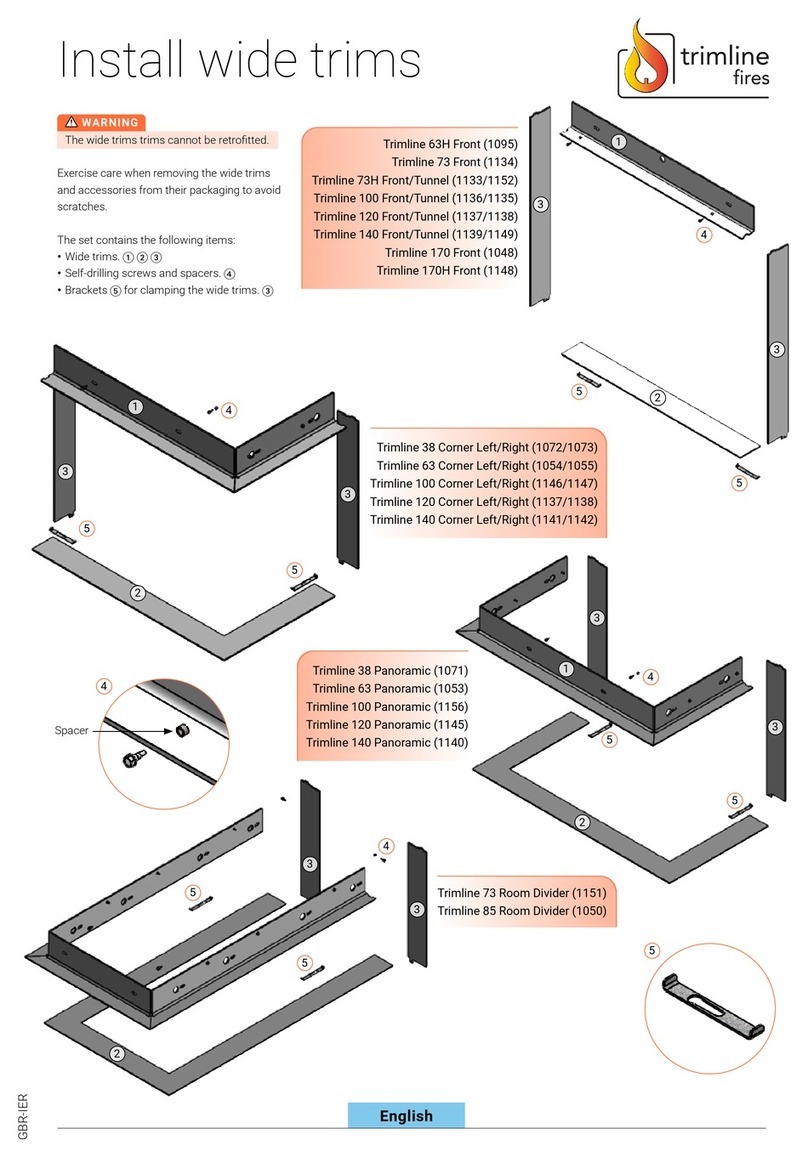
Place the top frame trim ① on the nishing edge on the front panel
on the stove ❶. Centre the trim accurately relative to the centre of the
stove (drawing), align the top trim with the front trim edge. In the case
of stoves with predrilled xing holes, secure the upper trim using the
screws and spacers provided. Do not over tighten the screws, thetrim
needs to be able to slide.
In the case of stoves with no predrilled xing holes, the top frame trim
① must be fastened to the existing front panel using the self-drilling
screws. After pre-drilling with the self-drilling screws, remove thefront
panel from the appliance and drill a 5mm hole in the convection box
❷. Ret the front panel and fasten the top frame trim using the screws
and spacers. Do not over tighten the screws, the trim needs to be able
toslide.
CAUTION
In the case of the Trimline 63H F, 73 F and 73H T models, the 2 vertical
glazing bars❸ must be removed before tting the side trim ③.
Theseglazing bars are no longer required.
5mm holeAlignment
Finishing edge
STEP 2
Loosen the left-hand and right-hand hexagon socket head screws that
secure the bottom glazing bar. Fit the left-hand and right-hand trims ③;
they hook behind the top wide trim. ①
Fit the brackets ⑤ on the left and right, slide them against the wide
trims and retighten the hexagon socket head screws. ❹
STEP 3
CAUTION
Work carefully to avoid damaging the wide trims.
The wide trims ②can now be positioned between the side trims ③.
CAUTION
The built-in construction may not make contact with the wide trims
due toexpansion of the stove when hot.
While tting the remaining refractory material, ensure a clearance gap
of a few millimetres to the wide trims. The nishing edge on theframe
surrounds the glass. ❺


