EN I 11
5.2 Installation of high temperature sensor AWU
Place the high temperature sensor in the specified input in the product and tighten it (in the case of Hoxter products). If the appliance
does not have such an input or it is not possible to install the high temperature sensor in it, put it in the flue gas path.
5.3 Air inlet flap installation AW
1. Connect the air inlet flap by aluminium flexible pipe (not included) with the fireplace insert or stove doors. The connection between
the air inlet flap and the product must be air-tight.
2. When installing into closed-in build, the air inlet flap must be placed outside the environment with high temperature. The heat
resistance of the air inlet flap is max 50 °C.
If you want to control the fireplace using electronic combustion control only and if you want to disassemble manual air control, follow
these instructions:
5.4 Installation of heat sensors PT1000 and sensor sump W
1. Module W contains 3 pieces of heat sensors PT1000 with different coloured connectors and 1 piece of sump for heat sensor.
2. Install the heat sensor sump in the heat exchanger of Hoxter water heating fireplace insert (follow the instructions attached
tothe product).
3. Mount the heat sensor PT1000 marked yellow in the sump in the heat exchanger of the fireplace insert. Put the sensor at least
60mm deep.
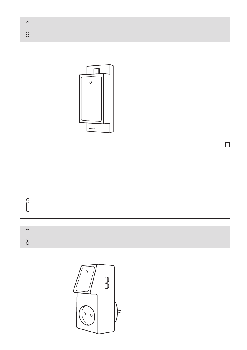
Option A (flat air control lever)
1. Set the air control to opened position (maximum air).
2. Remove the air control lever (dotted).
3. As an accessory, it is possible to order a hole cover, which
can be mounted instead of the lever.
Option B (round air control lever)
1. Set the lever to opened position (maximum air).
2. Remove the air control lever (dotted).
3. Turn the hole in the cap not to be visible from the front.
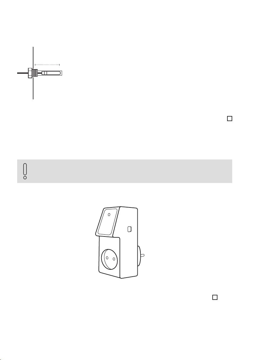
Install the high temperature sensor at least 20 mm deep into the hot zone. For proper functionality,
always install high temperature sensor before the attached accumulation mass (if available).
For the proper function of the electronic combustion control, it is always necessary to open the
manual air control to the maximum.
≥ 20 mm
Fig. 6 / Position of the high temperature sensor
Fig. 7 / Disassembly of the manual air control lever on the fireplace insert
To ensure correct measurement the high
temperature sensor must be calibrated
every2 years.