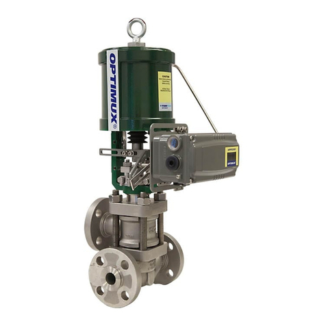
Trimteck OPTIMUX OpDx Specification sheet

Product Instruction Manual
Leading Technologies
For Control
OpDx
Butterfly Control Valve
INTRODUCTION
Scope of Manual
This instruction manual includes installation,
maintenance, and parts information for the
OptimuxTM OpDx control valve. Refer to
separate manuals for information regarding
installation, operation, and maintenance of
additional features such as actuators,
positioners, special accessories, fail-safe
systems, etc. Only qualified persons should
install, operate, and maintain an Optimux OpDx
valve. Any questions about these instructions
should be directed to your Optimux sales office
or sales representative before proceeding.
This publication does not contain information on
Optimux positioners. Refer to the appropriate
manual for information on positioner installation,
operation, maintenance, and calibration.
Note:
Selecting the proper fastener material is
the responsibility of the customer. Typically,
the supplier does not know what the valve
service conditions or environment may be.
Optimux's standard body bolting material is
B7/2H. B8 (stainless steel) is optional for
applications above 800• F and with stainless
steel or alloy body valves. The customer
therefore must consider the material's
resistance to stress corrosion cracking in
addition to general corrosion. As with any
mechanical equipment, periodic inspection
and maintenance is required. For more
information about fastener materials, contact
your local Optimux representative or factory.
Unpacking
1. While unpacking the valve, check the
packing list against the materials received.
Lists describing the valve and accessories
are included in each shipping container.
2. When lifting the valve from the shipping
container, position lifting straps to avoid
damage to tubing and mounted accessories.
TABLE OF CONTENTS
INTRODUCTION
Scope of Manual ............................ pg. 1
Safety Information ..........................pg. 1
Unpacking ...................................... pg. 1
INSTALLATION .............................. pg. 2
Quick-Check .................................. pg. 2
MAINTENANCE ............................ pg. 3
ASSEMBLY AND DISASSEMBLY
Valve Removal from Line .............. pg. 4
Actuator Removal .......................... pg. 4
Body Disassembly.......................... pg. 5
Body Reassembly .......................... pg. 5
REMOUNTING ACTUATOR .......... pg. 6
SAFETY INFORMATION
WARNING: Indicates a potentially
hazardous situation, which, if not
avoided, could result in death or
serious injury.
CAUTION: Indicates a potentially
hazardous situation, which, if not
avoided, could result in minor or
moderate injury and/or property
damage.
Note: Indicates a potential situation,
which, if not avoided, may result in an
undesired result or state.

OpDx Butterfly Control Valve
2
Valves up through 14-inch may be lifted by
the actuator lifting ring. On larger valves, lift
the valve using lifting straps or hook
through the yoke legs and outer end of the
body.
3. In the event of shipping damage, contact
your shipper immediately.
4. Should any problem arise, contact your
Optimux representative.
INSTALLATION
1. Before installing the valve, clean the line of
dirt, scale, welding chips, and other foreign
material. Clean the gasket surfaces
thoroughly to insure leak-proof joints.
2. Check flow direction to be sure valve is
installed correctly. Fail-closed valves
should be installed with the shaft upstream
only on gas service. It is preferred that
liquid service valves must be installed with
the shaft downstream regardless of air
failure action. However, under certain flow
conditions the valve can flow shaft
upstream. Consult factory if the valve must
be mounted with the shaft upstream in
liquid service. Fail-open valves should be
installed with the shaft downstream.
WARNING: When installing the
valve in-line between flanges,
make certain the flange face
gasket covers both seat
retainer and body and
surface. Failure to do so will
cause excessive leakage
downstream. Refer to “Seat
Insert/Snap-ring Configuration”
in Figure 1.
3. Fully close the valve before and during the
installation process.
WARNING: Keep hands, hair,
clothing, etc. away from the
rotating disc and the seat when
operating the valve.
CAUTION: Because of
Optimux’s self-centering seat,
there is no reason to open the
valve at any time during
installation. Therefore, the
valve should remain closed
until it is fully installed.
4. Connect air supply and instrument signal.
Throttling valves are usually equipped with
valve positioners. Two connections are
marked for the air supply and for the
instrument signal. Cylinder actuator is
suitable for 150 PSI air supply. An air filter
is recommended unless the supply air is
unusually clean and dry. All connections
must be free of leaks.
CAUTION: On valves equipped
with air filters, the air filter bowl
must point down; otherwise,
the air filter will not perform
properly.
Note:
In some rare cases, the air supply must
be limited to 100 PSI rather than 150 PSI. In
this case, a sticker found near the upper air
port on the cylinder will indicate this and an
air regulator should be installed to insure the
supply pressure does not exceed 100 PSI.
5. Make sure proper clearance exists
internally in the mating piping to permit
proper disc rotation.
6. Apply recommended torque values to line
flange bolting for proper sealing (see Table I).
Quick-check
Prior to start-up, check the control valve by
following these steps:
1. Check for full stroke by making the
appropriate instrument signal change.
Observe disc position indicator plate
mounted on the transfer case. The disc
should change position in a smooth, rotary
fashion.

Product Instruction Manual
3
2. Check all air connections for leaks. Tighten
or replace any leaky lines.
3. Evenly tighten the packing nuts to slightly
over finger-tight.
CAUTION: Do not over-tighten
packing. This can cause excessive
packing wear and high shaft friction,
which may impede shaft rotation.
After the valve has been in operation
for a short time, check the packing
nuts to make sure they are just over
finger-tight (readjust if necessary). If
packing box leaking occurs, tighten
the packing nuts only enough to stop
leakage.
4. To observe the valve failure mode in case
of air failure, position the valve to midstroke
and shut off the air supply or disconnect the
instrument signal. By observing the
indicator plate, the disc should either fail
open or closed. If incorrect, refer to the
“Actuator Action Reversal” section in the
appropriate Spring Cylinder Actuator
Instruction Manual.
MAINTENANCE
At least once every six months, check for
proper operation by following the preventive
maintenance steps outlined below. These
steps can be performed while the valve is in
line and, in some cases, without interrupting
service. If an internal problem is suspected,
refer to the Disassembly and Reassembly
section.
1. Look for signs of gasket leakage through
body and line flanges. Tighten flange
bolting if necessary.
2. Note if any corrosive fumes or process
drippings are damaging the valve.
3. Clean valve and paint any areas of severe
oxidation.
4. Check packing box bolting for proper
tightness. Packing nuts should be slightly
over finger-tight; however, tighten as
necessary to prevent stem leakage.
CAUTION: Do not over-tighten
packing.
5. If valve is supplied with a lubricator, check
lubricant supply and add lubricant if
necessary.
6. If possible, stroke valve and check for
smooth, full-stroke operation by observing
the disc position indicator plate mounted on
the transfer case. Unsteady movement of
the disc could indicate an internal valve
problem (jerky motion is normal whenever
Grafoil packing is used).
Valve Size
(inches)
2
3
4
6
8
10
12
14
16
18
20
24
30
Rating
150
300
600
150
300
600
150
300
600
150
300
600
150
300
600
150
300
150
300
150
150
150
150
150
150
Torque
(ft./lbs.)
118
118
118
118
209
209
118
209
337
209
209
505
209
337
728
337
505
337
728
505
505
728
728
1009
1009
Table I: Flange Bolting Torques

OpDx Butterfly Control Valve
4
7. Check positioner calibration by observing
the gauges and the disc position indicator
plate. Make sure the positioner is calibrated
to the correct range.
8. Remove transfer case cover plate and
make sure the positioner linkage and
internal actuator parts are securely
fastened. Also, check for air leaks through
actuator stem seal, using a soap solution.
CAUTION: Never apply air to the
actuator without the cover
plate installed; otherwise, the
unsupported shaft may sustain
damage.
9. Be sure that all accessories, brackets and
bolting are securely fastened.
10. If possible, remove air supply and observe
stroke plate for correct fail-safe action.
11. Spray soap solution around the cylinder
retaining ring and the adjusting screw to
check for air leaks through the O-rings.
12. Clean any dirt or other foreign material
from the exposed portion of the shaft.
13. If an air filter is supplied, check and replace
cartridge if necessary.
ASSEMBLY AND DISASSEMBLY
Valve Removal from Line
If an internal valve problem is suspected with
the valve and disassembly is required, remove
the valve from the line by proceeding as
follows:
WARNING: Depressurize line to
atmospheric pressure, drain
all process fluids and decontaminate
the valve (if caustic or hazardous
materials are present).
1. Make sure valve is fully closed.
Note:
On valves with fail-open action, air
pressure must be supplied under the
actuator piston to close the valve. If the valve
is supplied with a handwheel, it can be used
to close the valve.
2. Attach a hoist or some means to support
the valve.
3. Remove the line bolting. Do not attempt to
pry line flanges apart by pushing or pulling
on valve actuator.
4. Slide the valve carefully from the line. To
avoid damage to gasket surfaces, do not
twist the valve.
5. After the valve is completely removed from
the line, slowly relieve air pressure from the
actuator.
Actuator Removal
In most cases, both the body assembly and the
actuator are easier to disassemble with the
actuator removed from the body. To do so,
proceed as follows:
1. Support actuator assembly by the lifting
ring before disconnecting it from the body
assembly.
2. Remove the transfer case cover bolts.
Carefully pry or slide the cover plate from
the end of the shaft.
3. On Optimux actuators with a clamping lever
arm design, loosen the linkage bolt.
4. Loosen the actuator adjusting screw to
release spring pressure.
5. Remove the bolts connecting yoke to the
actuator subassembly.
6. Slide entire actuator assembly off the shaft.
For Optimux actuators with a clamping
lever-arm design, it may be necessary to
wedge the halves of splined lever arm apart
to loosen it from the shaft splines.

Product Instruction Manual
5
Body Disassembly
To disassemble the body, refer to Figures 1, 2
and 5 and proceed as follows:
1. On Optimux valves supplied with seat
retainer screws, remove the seat retainer
screws and retainer clips. Lift the seat
retainer out of the valve body. (Refer to
Figures 1A, B, C).
2. On valves supplied with retainer snap-ring
configuration, carefully insert a screwdriver
in the key slot provided in the retainer; pry
the retainer and snap ring out of the valve
body. (Refer to Figure 1D).
3. Remove the gland flange by removing both
packing nuts. It is not necessary to remove
the studs.
4. Drive the taper pins out of the disc by
tapping on the small end of the pins using a
punch and hammer.
5. Remove the end plug (optional bolted
flange and seal if applicable).
6. Remove shaft by inserting a press or a
nylon rod (or similar material) into body’s
blind end, and using a hammer, carefully
tap the shaft through the body.
CAUTION: Take special care not
to damage the splined end of
the shaft during disassembly.
To prevent scratching the sealing surface of
the disc while removing the shaft, place
supports underneath the disc. This also
prevents the shaft from binding in the body
as the shaft comes off the bearing surfaces.
7. Push the packing and bearings out of the
body using a dowel of appropriate
diameter. Push the packing from the center
of the valve.
Body Reassembly
To reassemble the body subassembly, refer to
Figures 1, 2, 3, and 5 and proceed as follows:
1. Clean all parts.
2. Check the disc seating surface to make
sure it is smooth and free of scoring and
scratches.
CAUTION: Damaged or dirty
seat surfaces can cause
excessive seat wear and high
torque requirements. Damaged
discs should be replaced.
3. Inspect shaft for scratches or galled
surfaces. For maximum performance,
Optimux shafts are machined to a very
smooth finish. If damage exists, replace the
shaft or contact factory representative.
Note:
Disc and shaft are interchangeable in
recent designs. Replacing the disc does not
require replacing the shaft. Earlier designs
require that the disc and shaft be machined
together. Contact the factory for matched
disc and shaft.
4. Insert new sliding stem shaft bearings into
the body. (A press may be required with
some designs.)
Note:
Earlier Optimux designs require the
disc to be aligned in the body in such a way
that it can rotate properly. Align the shaft
bearings on either side of the disc and insert
the shaft through the body, bearings and
disc.
5. Position the disc in the body, making sure it
will rotate in the proper direction with
respect to the body’s internal disc stop.
Slide the shaft through the body, bearings
and disc.
CAUTION: Exercise care while
sliding the shaft into the sliding
stem shaft bearings to avoid
damage to both the shaft and
bearings.

OpDx Butterfly Control Valve
6
6. Insert new taper pins and drive them firmly
into place in the side opposite the stop.
7. Slide the packing retainer, lower packing,
packing spacer, upper packing, and
packing follower over splined end of the
shaft and into the body. Typical packing
configurations are shown in Figure 3.
Note:
Always use new packing whenever
rebuilding the packing box.
CAUTION: Since the sealing on
V-ring packing takes place at
the feather edge, it is important
to avoid damage to that edge.
8. Reinstall the end plug (or replace the end
seal and reinstall the bolted flange).
9. Reinstall the gland flange and packing nuts.
Tighten packing evenly to slightly over
finger-tight.
CAUTION: Do not over-tighten
packing. This can cause
excessive packing wear and
high shaft friction, which may
impede shaft rotation.
10. All seat configurations with screw/clip
retainers require a gasket (item No. 55)
installed in the appropriate groove. This is
accomplished by pressing the gasket into
the appropriate groove.
11. If the seat retainer is the screw/clip type
and has a soft or dual seat, press the soft
seat into the soft seat retainer or metal
seat. (There should be an interference
between the soft seat and the retainer.)
With the valve in the closed position,
secure the retainer or metal seat in place
by tightening the retainer clips and screws.
This allows the seat to align with the disc,
permitting tight shutoff.
12. If the seat retainer is the screw/clip type
with a metal seat design, a gasket will need
to be installed in the metal seat prior to
clipping the seat in place with the seat clips
and screws.
Note:
Optimux valves of earlier design may
require that the disc be open while installing
the soft seat into the body. (Refer to Figure
1D.)
13. If an early design Optimux seat retainer
has an indexing groove to accept a soft
seat, press the corresponding seat into the
retainer groove. Install the seat retainer
subassembly into the body.
14. On valves supplied with the retainer snap-
ring configuration, install the snap-ring into
the groove around the retainer (or metal
seat). Start the retainer into the body with
the open ends of the snap-ring in the body
groove. Gently press the snap-ring into the
retainer until both the retainer and snap-
ring slip into the body. (Refer to
Figure 1D.)
15. On early design Optimux valves supplied
with seat retainer screws, install the insert
and retainer into the body with the disc
open. Loosely install the retainer screws,
then close the disc. Tighten the screws
after the closed disc has centered the seat.
This allows the seat to align with the disc,
permitting tight shutoff.
REMOUNTING ACTUATOR
Before mounting an Optimux actuator on the
valve body, verify that the disc rotation
matches the actuator rotation and complies
with the air failure requirements. Procedure for
mounting the actuator is as follows:

Product Instruction Manual
7
1. Slide the entire actuator assembly onto the
shaft. If necessary on Optimux actuator
designs with clamping lever arm design,
wedge the splined lever arm apart to loosen
it on the shaft splines. For full rotation of the
disc, marks provided on the end of the shaft
and on the lever arm should be aligned.
2. Bolt the actuator yoke to the valve body. Be
certain the stroke indicator plate is
positioned properly to accurately indicate
the valve's rotation.
3. Position the actuator lever arm on the shaft
so the actuator stem is centered in the
transfer case. Firmly tighten the linkage
bolt, on clamping lever arm actuators.
CAUTION: On clamping lever-
arm actuators, do not apply air
to the actuator without
the cover plate installed;
otherwise, the unsupported
shaft may sustain damage.
4. Adjust the actuator stroke stop bolts until
the disc is parallel to the seat surface, but
not resting on body disk stop.
CAUTION: Actuator stroke stop
bolts must be properly
adjusted, to prevent the valve
disc from overstroking. If
incorrectly adjusted the valve
shaft may be twisted or sheared
off.
5. Install valve in line as outlined in
Installation
section.
A – Dual Seat B – Metal Seat C – Soft Seat D – Seat Insert / Snap-ring
Note: Item numbers correspond directly to the bill of material.
Refer to the bill of material for specific part numbers.
Figure 1: Seat Retainer Configurations

OpDx Butterfly Control Valve
8
Figure 2: Body Assembly
Note: Item numbers correspond directly to the valve's bill of material.
Refer to it for specific part numbers.
Shaft
Plug
(Item No. 122)
Disc
(Item No. 50) Shaft Bearing (Item No. 83)
Taper Pins (Item No. 52)
Shaft (Item No. 51)
Inner Packing (Item No. 88)
Outer Packing (Item No. 88)
Packing Follower (Item No. 87)
Packing Spacer(s) (Item No. 93 - 95)
Packing Retainer (Item No. 85)
Seat Retainer Clip (Item No. 123)Seat Retainer Bolt (Item No. 124)
O-ring
(Item No. 61) Shaft
Bearing
(Item No. 83) Disc Stop
Body
(Item No. 1)
Seat
Figure 3: Typical Packing Configurations
Standard Square Standard Single "V"
Standard Single "V"
Twin "V"
PTG
(Packing studs rotated 45 degrees)
PT PTG / PT
Fire-safe Option
(Live-loading omitted)

Product Instruction Manual
9
424 42422
333
3Left-hand
Mounting
Right-hand
Mounting
Style A
Fail-closed
Air-to-open
Shaft Upstream
Style B
Fail-closed
Air-to-open
Shaft Upstream
Style C
Fail-closed
Air-to-open
Shaft Downstream
Style D
Fail-closed
Air-to-open
Shaft Downstream
Right-hand Mounting
Facing Downstream
Left-hand Mounting
Facing Downstream
1111
Style C Style D Style B Style A
FLOW
Figure 4: Transfer Case Mounting
Note: Orientation 1 is standard. Orientation positions 2 and 4 are not available
in some actuator sizes. Contact Optimux representative or factory.

OpDx Butterfly Control Valve
10
Item No. Description
1 body
20 hard seat
21 seat insert
22 seat retainer
50 disk
51 shaft
52 taper pins
55 seat gasket
61 O-ring
80 gland flange
83 shaft bearing
85 packing retainer
87 packing follower
88 packing
93 packing spacer
109 packing box stud
117 packing box nut
122 shaft plug
123 clip
124 screw
122 61
83 52
1
83
21
55
20/22
124
123
50
85
88
93
88
87
80
109
117
51
Figure 5: Exploded Body Sub-Assembly
Note: Item numbers correspond directly to the bill of material. Refer to it for specific part numbers.

Product Instruction Manual
11
Troubleshooting OpDx Buterfly Control Valve
Problem Probable Cause Corrective Action
Valve moves to failure
position, excessive air
bleeding from transfer case
1. Failure of actuator O-ring
2. Failure of sliding seal assembly
1. Replace actuator stem O-ring
2. Repair or replace sliding seal assembly
Jerky shaft rotation 1. Overtightened packing
2. Improper adjustment of lever arm on
shaft causing arm to contact transfer case
3. Cylinder wall not lubricated
4. Worn piston O-ring allowing piston to
gall on cylinder wall
5. Worn actuator stem O-ring causing
actuator stem to gall on stem collar
6. Worn (or damaged) shaft bearings,
shaft bearings or packing followers
1. Retighten packing box nuts to slightly over
finger-tight
2. Readjust lever arm (see step 1 in the
Remounting Actuator section)
3. Lubricate cylinder wall with silicone lubricant
4. Replace O-ring; if galling has occurred
replace all damaged parts
5. Replace O-ring; if actuator stem is galled
replace it
6. Disassemble and inspect parts; replace
any worn or damaged parts
Excessive leakage 1. Improper adjustment of external
stroke stops
2. Worn or damaged seat
3. Damaged disc seating surface
4. Improper handwheel adjustment
acting as limitstop
1. See
Adjusting External Stroke Stops
section
2. Replace seat
3. Replace disc and shaft
4. Adjust handwheel until disc seats properly
Leakage through line 1. Dirty line gasket surfaces
2. Improper sealing of line flanges
3. Flange or pipe misalignment
1. Clean gasket surfaces and reinstall valve
2. Tighten line flanges evenly and
completely (see Table I for proper torque)
3. Clean body bore and stem, replace packing
Leakage through
packing box
1. Loose packing box nuts
2. Worn or damaged packing
3. Dirty or corroded packing
1. Tighten packing box nuts to slightly over
finger-tight
2. Replace packing
3. Clean body bore and stem, replace packing
Disc interferes with body 1. Disc installed upside down
2. Worn shaft bearings
1. Reinstall disc
2. Replace shaft bearings
Disc interferes with line 1. Cement lining or heavy schedule pipe 1. Modify line to allow proper disc clearance
Valve slams, won't open, or
causes severe water hammer
1. Improper valve installation 1. See step 2 in Installation section and
correct flow direction
Shaft rotates, disc remains
open or closed
1. Missing or broken taper pins
2. Broken shaft
1. Replace taper pins
2. Replace shaft, make sure shaft is not
overstressing on external stroke stop
Actuator operates, shaft
does not rotate
1. Broken internal actuator parts 1. Refer to appropriate actuator Maintenance
Instructions

OpDx Butterfly Control Valve
Optimux customers should be aware that Optimux products might be used in numerous applications under a wide variety of industrial
service conditions. Although Optimux can (and often does) provide general guidelines, it cannot provide specific data and warnings
for all possible applications. The purchaser/user must therefore assume the ultimate responsibility for the proper sizing and selection,
installation, operation and maintenance of Optimux products. The purchaser/user should read and understand the Product Instruction
Manual (PIM) included with the product, and train its employees and contractors in the safe use of Optimux products in connection
with the specific application.
While the information and specifications presented in this literature are believed to be accurate, they are supplied for informative
purposes only and should not be considered certified or as a guarantee of satisfactory results by reliance thereon. Nothing contained
herein is to be construed as a warranty or guarantee, express or implied, regarding any matter with respect to this product. Because
Optimux is continually improving and upgrading its product design, the specifications, dimensions and information contained herein
are subject to change without notice. Should any question arise concerning these provisions, the purchaser/user should contact
TRIMTECK, LLC at any of its worldwide operations or offices.
For more information, contact:
FORM # PIM0910
For more information about Trimteck and its products,
contact www.trimteck.com or call USA (954) 753-5545
TRIMTECK LLC
12461 NW 44th Street
Coral Springs, FL 33065
Phones: (954) 753-5545
Fax: (954) 753-5561
Table of contents
Other Trimteck Control Unit manuals