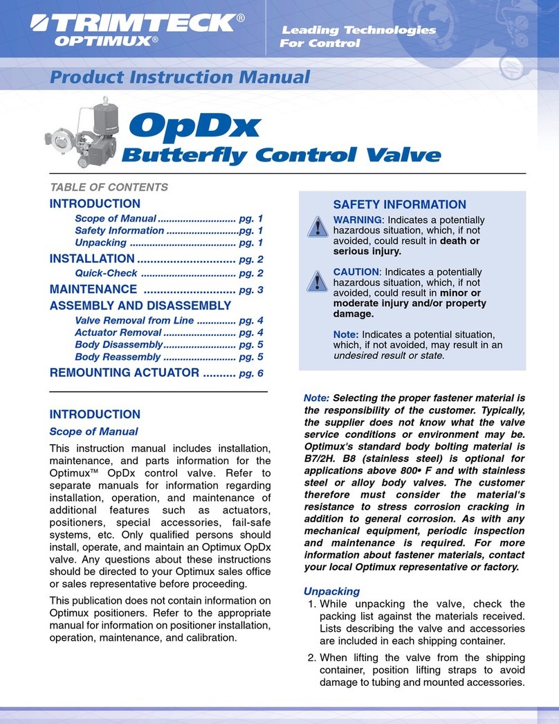
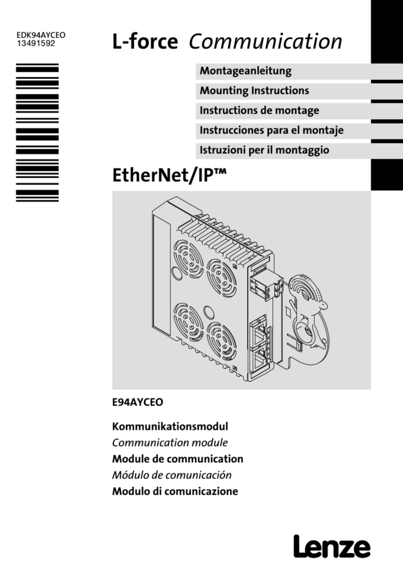
Trimteck Optimux OpGL User manual

OpGL
Globe Control Valve
Product Instruction Manual
Leading Technologies
For Control
INTRODUCTION
Scope of Manual
This instruction manual includes installation,
maintenance, and parts information for the
Optimux OpGL control valve. Refer to separate
manuals for information regarding installation,
operation, and maintenance of additional
features such as the special trim diaphragm
actuator, handwheel, extension bonnets, etc.
Only qualified persons should install, operate,
and maintain an Optimux OpGL valve. Any
questions about these instructions should be
directed to your Optimux sales office or sales
representative before proceeding.
This publication does not contain information on
Optimux positioners. Refer to the appropriate
manual for information on positioner installation,
operation, maintenance, and calibration.
Description
The OpGL is a spring-cylinder actuated globe
valve in which the supply air pressure and the
fluid pressure combine forces to produce an
exceptionally tight shutoff. In addition, self-
aligning seat rings make shutoff easier to
achieve. Valve specifications are as follows:
Table 1: Specifications
TABLE OF CONTENTS
INTRODUCTION
Scope of Manual ............................ pg. 1
Description...................................... pg. 1
Specifications ................................ pg. 1
Safety Information ........................ pg. 1
Unpacking ...................................... pg. 2
INSTALLATION .............................. pg. 2
MAINTENANCE ............................ pg. 3
ASSEMBLY AND DISASSEMBLY
Body Disassembly.......................... pg. 4
Body Reassembly .......................... pg. 5
Actuator Disassembly.................... pg. 7
Actuator Reassembly .................... pg. 8
AIR-ACTION REVERSAL
Air-to-Open .................................... pg. 9
Air-to-Close .................................... pg. 9
SAFETY INFORMATION
WARNING: Indicates a potentially
hazardous situation, which, if not
avoided, could result in death or
serious injury.
CAUTION: Indicates a potentially
hazardous situation, which, if not
avoided, could result in minor or
moderate injury and/or property
damage.
Note: Indicates a potential situation,
which, if not avoided, may result in an
undesired result or state.
Diameter
Body Style
Connections
Materials
Bonnet Types
Internals
1/2 ’’- 42’’ : ANSI Class 150-600
Globe, Angle, Three-way, Steam-
jacketed, Y-body
Separable flanges, Internal flanges,
Socketweld, Buttweld
Carbon Steel, Stainless steel, Chrome-
molly, Alloy, Hastelloy, B&C, Titanium,
and others…
Normal, Extended, Cryogenic, Coal box
extended
Flow characteristics, equal percentage,
linear, and quick-open. Seats available
in metal or soft (for "bubble tight" shut
off)

2
Unpacking
1. While unpacking the valve, check the
packing list against materials received.
Lists describing valve and accessories are
in each shipping container.
2. When lifting the valve from shipping
container, position the lifting straps through
the yoke legs to avoid damage to the tubing
and mounted accessories.
WARNING: When lifting an
actuator with lifting straps
through the yoke legs, be aware
that the center of gravity may
be above the lifting point.
Therefore, support must be
given to prevent the actuator
from rotating.
3. Contact your shipper immediately if there is
shipping damage.
4. Should any problem arise, call your
representative.
INSTALLATION
1. Before installing the valve, inspect it, and
other associated equipment, for any
damage and any foreign material.
2. Be sure that the body interior is clean, that
pipelines are free of foreign materials, and
that the valve is oriented in such a way that
pipeline flow is in the same direction as the
arrow on the side of the valve.
3. The assembly of the control valve may be
installed in any orientation unless otherwise
limited. However, whenever possible, the
valve should be installed with the actuator
vertical above the body. This is also
important for cryogenic applications to keep
the packing isolated from the flowing
medium, permitting the packing
temperature to remain close to ambient
temperature.
CAUTION: Do not insulate
extension bonnets that are
provided for hot or cold
services.
4. Be sure to allow sufficient overhead
clearance to provide for disassembly of the
plug from the valve body. Refer to
Table 2 below for overhead clearance
requirements.
Table 2: Overhead Clearance
Requirements
5. If welding the valve into the line, use
accepted piping and welding practices. In
the case that the valve has separable end
flanges, the half rings must be installed on
the body before bolting the valve into the
line in order to insure a tight connection.
WARNING:Failure to install half
rings on the valve body could
result in serious injury.
Note: Depending on valve body materials
used, post weld heat-treating may be
required. This may cause damage to internal
elastometric and plastic parts. Shrunk-fit
pieces and threaded connections may also
loosen. In general, if post weld heat-treating
is to be performed, all trim parts should be
removed. Contact your Optimux sales office
for additional information.
OpGL Globe Control Valve
Valve Size
(inches)
1/2, 3/4, 1
1 1/2, 2
3
4
6
8
10
12
Clearance
(inches/mm)
3/76
5/127
6/152
8/203
10/254
13/330
14/356
15/381

3
6. Connect air supply and instrument signal
(air or mA) lines. Throttling control valves
are equipped with a valve positioner. Two
connections are marked: One for the air
supply and the other for the instrument
signal. Both the actuator and positioner are
suitable for 150 psi/10.3 Bar air supply. An
air regulator is not required unless the
supply pressure exceeds 150 psi/10.3 Bar.
The air filter should be installed before the
positioner unless the supply air is unusually
clean and dry.
CAUTION: On valves equipped
with air filters, the filter
must point down for proper
performance.
Note: In some unusual cases, air supply must
be limited to less than the previously
mentioned amount of 150psi/10.3 Bar. In this
case, a sticker found near the upper air port
on the actuator cylinder will indicate this and
an air regulator should be installed to insure
that the supply pressure does not exceed the
line pressure indicated on the sticker.
MAINTENANCE
Valve parts are subject to normal wear and
must be inspected and replaced as necessary.
Inspection and maintenance frequency
depends on the severity of service conditions.
This section contains preventive maintenance
steps which can be performed while the valve
is still in-line and, in some cases, still in
service. If a problem is suspected of being
internal, refer to the Assembly/Disassembly
section.
1. Inspect end flanges and bonnet for signs of
gasket leakage. Tighten flange and bonnet
bolting (if required). See Table 4
2. Check the pressure-balance sleeve, metal
bellows seal, body drain plug, etc. (if
included) for fluid leakage to the
atmosphere.
3. Keep valve clean and repaint areas
affected by severe oxidation
4. Examine the valve for damage caused by
corrosive fumes or process drippings.
5. Check lubricant supply and add lubricant if
necessary. See Table 3 for common
lubricants.
6. Packing box bolting must be slightly over
finger-tight. Tighten only as necessary to
prevent stem leakage.
CAUTION: Do not over-tighten
packing. This may cause
excessive packing wear and
high stem friction, which can
Product Instruction Manual
Lubricant
Krytox 206
GP 460
Aeroshell
Grease 7
Garlock
Luball
Manufacturer
E.I. DuPont
Graphite
Products Co.
Shell Oil Co.
Garlock Inc.
Temperature Range
-5º to 550º F /
-20º to 285º
32º to 1000º F /
0º to 540º C
-100º to 300º F /
-75º to 150º C
32º to 500º F /
0º to 260º C
Description Applications
Fluorinated general purpose grease; handles common
liquids and gases; good lubricity in harsh mediums; non-
flammable, chemically inert; will not harm plastic or metal
parts
Graphite in petrolatum; high pressures; anti-galling,
graphite remains above 600º F/ 316º C
Synthetic oil based; low temperature applications
General purpose molybdenum disulfide lubricant
economical; good in water, steam and common chemicals;
not good in harsh mediums where Krytox 206 is
recommended
Table 3: Common Lubricants

4
impede stem movement.
7. Be sure that all accessories, brackets, and
bolts are securely fastened.
8. Check rubber bellows for wear.
9. Remove any foreign substances from the
plug system.
10. Spray a soap solution around the cylinder
actuator that retains the ring, adjust screw
and actuator stem guide for air leaks
through the O-rings.
11. If possible, remove air supply and observe
actuator for correct fail-safe action.
12. If the valve contains an air filter, check and
replace cartridge if necessary.
13. Be certain that stem clamp and positioner
linkage are securely fastened. If the stem
clamp is loose, check the plug thread
engagement. (For the correct procedure
on aligning the plug with the seat, refer to
the "Reassembly of the Actuator" section of
this manual).
14. Stroke the valve, if possible, and check for
smooth, full stroke operation. Wobbly stem
movement could be a sign of an internal
valve problem.
Note: Erratic stem movement is common
whenever Grafoil packing is utilized.
WARNING: Keep hands, hair,
clothing, etc. away from all
moving parts when operating
the valve.
ASSEMBLY AND DISASSEMBLY
Body Disassembly
In disassembling the valve body, refer to Figure
4 and continue as follows:
WARNING: Depressurize line to
atmospheric pressure and
drain all fluids before
commencing work on the valve.
1. If valve is air-to-close, skip to step 2. If
valve is air-to-open, apply air under piston
to raise the plug off the seat before taking
the valve apart.
2. Take out the bonnet flange bolting which
will allow for removal of the actuator,
bonnet, and plug from the valve.
CAUTION: Heavy actuators may
require a hoist. A lifting ring is
provided on most valves for
this function; otherwise, lift the
valve with the yoke legs using a
lifting strap and a hoist. Care
should be taken to lift the
actuator and plug straight out
of the body to avoid damage to
the seat as well as to the plug.
3. Lift retainer, seat ring, and gaskets from the
body.
4. See to it that the seating surfaces on both
the seat ring and plug are free of damage
so that a tight shutoff is ensured. Be sure
that gasket surfaces on the seat ring,
bonnet, and body are clean and
undamaged.
5. To inspect the plug, remove by loosening
the stem clamp and gland flange, also, take
off the yoke clamps.
Note: With air-to-close, fail-open valves, it
may be necessary to apply a small amount of
air to the top of the actuator to move the plug
away from the bonnet. If not, some irritation
may occur to the plug.
Turn the actuator off the plug and bonnet
without allowing the plug to rotate inside the
bonnet. Remove the plug carefully through the
packing box.
6. If re-machining is necessary on the seat
surfaces, both surfaces on plug and seat
must be reworked. The seat angle on the
plug is 30 degrees; the seat ring is 33
degrees. Lapping will not be necessary if
proper assembly procedures are followed.
OpGL Globe Control Valve

5
CAUTION: In the case that re-
machining is necessary, be
sure to protect the stem during
turning. Insure concentricity of
the seat surface with the plug
stem (or outside diameter of the
seat ring, if machining the
seat).
7. To replace packing or change the packing
box configuration, push out the packing,
spacer, and guides with a dowel of a similar
size as the plug stem.
WARNING: For valves equipped
with separable end flanges, do
not machine the body gasket
surfaces. Machining could
cause gasket leakage and
failure of the valve.
8. In the case that separable end flanges
need to be removed, file off tack welds or
pull rivets behind the flanges.
CAUTION: If separable end
flanges and spiral wound
gaskets are used, use gaskets
with outer back-up rings.
Failure to do so could result in
excess stress in some
applications.
Note: To prevent flanges from dropping off
during shipping, a tack weld or stainless
steel rivet has been installed behind the end
flanges.
Body Reassembly
To reassemble the valve body, refer to Figure
4, and continue as follows:
1. In the case that packing was removed, refer
to Figure 2 and install new packing exactly
as shown. Be sure to leave at least 1/8-inch
at the top of the packing box for the top
guide to enter. Different spacer lengths
allow a wide variety of packing
configurations, such as twin seal and
vacuum pressure packing.
WARNING: Valves with extended
bonnets or metal bellows seals
must not have lower packing
installed. Rather, lower packing
rings should be installed with
the upper set.
Wherever graphite guides are used, the
graphite liners should be replaced each
time the valve packing is replaced. Under
no circumstance, should the valve be
replaced without graphite liners and guides.
2. Insert the plug stem into the packing box,
being sure not to scratch the stem or
guides.
3. Turn actuator back onto the plug, without
turning the plug inside the bonnet. Be
certain that the gland flange and bonnet
flange are in place prior to engaging the
plug stem and actuator stem threads.
Note: To prevent galling, do not let the gland
flange come into contact with the polished
plug stem.
Leave about three to four plug stem
threads exposed. Attach yoke clamp and
gland flange bolting. When working with
valves using a 2-inch spud, make sure that
the half rings are in place between the yoke
and bonnet. Tighten yoke clamp bolting
firmly.
4. Install new seat gaskets as well as a new
bonnet beveled edge up for Teflon gaskets.
5. Introduce the seat ring into the body with
the step side down. Place the seat retainer
into the body with the thin end of the
cathedral window down.
Product Instruction Manual

6
Note: For ANSI Class 900 and above valves,
valve sizes up through 1.5-inch, the seat
retainer window should be placed in the body
with the window facing toward the valve
ports. For valves 2-inches or greater in size,
the bar of the retainer should face toward the
valve ports.
6. For air-to-open valves, place air under the
actuator piston to retract the plug.
7. Let down the plug and body squarely into
the body. Take caution as not to scratch the
plug as it enters the body.
8. To properly align the seat ring and plug, first
bring the bonnet bolting to finger tightness.
a. If the actuator is pneumatic, apply air
pressure above the piston to seat the
plug in the seat ring, then skip to step 9.
b. If the actuator is electric or hydraulic,
move the actuator stem down until it is
fully extended. Then retract the actuator
stem 1/8-inch/3.175-mm. Mount the
stem clamp onto the plug stem/actuator
limit switches according to the operating
manual of the actuator.
Note: The following step (9) pertains only to
valves with pneumatic actuators. In the case
that an electric or hydraulic actuator is used,
return the plug to the mid stroke position and
proceed to tighten.
CAUTION: For electric or
hydraulic actuators, failure to
return the plug to a mid stroke
position will cause damage to
the actuator and/or the valve
while the bonnet is being
tightened.
9. If the valve is air-to-close, skip this step and
continue to step 10. Check for proper plug
seating in air-to-open valves as follows: If
proper seating occurs, the bonnet flange
will be forced up against the finger tight
body with such force that it will not be
possible to wriggle the flange. If improper
seating occurred, the bonnet flange can be
wriggled with light hand force. If this
occurs, place air under the actuator piston
and retract the actuator to approximate
mid-stroke position. Turn the plug out of
the actuator stem one additional thread and
repeat the seating procedure described
above. When the bonnet flange becomes
tight against the finger tight body bolting,
the plug is then properly seated.
10. For pneumatic actuators, put the plug in
the closed position. For electric, hydraulic,
or mechanical actuators, move the plug to
the mid-stroke position. Tighten the bonnet
flange bolting in such a way that will
maintain the bonnet flange square (or
parallel) with the body. Tighten the first bolt
1/6 of a turn, then,tighten the bolt directly
opposite 1/6 of a turn and so on around the
flange. Tighten all the bolts firmly and
evenly to compress the bonnet gasket and
seat the bonnet. Torque the bonnet bolts to
the suggested torque values in Table 4.
Table 4: Suggested Bonnet Bolting Torque
Values (ft. lbs. /Nm, ± 10%)
11. To seat the plug, apply air over the piston.
For throttling valves, adjust the stem clamp
so that, with full instrument signal to the
positioner, the full signal scribe line on the
positioner cam points to the center of the
cam roller bearing.
OpGL Globe Control Valve
Bolt Size
(inches)
5/8
3/4
7/8
1
1 1/8
1 1/4
1 3/8
1 1/2
1 5/8
1 3/4
1 7/8
2
Carbon Steel
80/108
140/190
230/312
350/475
510/690
730/990
990/1342
1320/1790
1710/2318
2170/2942
2700/3660
3350/4542
Stainless Steel
50/68
90/122
150/203
220/298
330/447
460/624
630/854
840/1140
1080/1484
1400/1898
1700/2305
2100/2847
Bolt/Stud Material

7
Note: Concerning on/off valves, the bottom
of the stem clamp should be lined up with the
bottom of the actuator stem (± 1/16-
inch/1.60mm).
Make the stem clamp bolting tight. Proper
tightness is important since this adjustment
fastens the actuator stem to the plug stem.
Adjust the stroke plate so that the stem
clamp points to the "closed" position.
12. Lastly, if the valve was taken out of the line,
when reinstalling, be sure that the flow
arrow shows correct flow direction.
Actuator Disassembly
When dealing with air-to-open valves, the
actuator may be disassembled while still on the
valve. In the case of air-to-close valves, the
actuator must be removed from the valve
before it is disassembled. Refer to Figure 5 to
disassemble the actuator. Proceed as follows:
Note: Steps 1-4 pertain to the removal of the
actuator from the valve. If the actuator is to
be disassembled while still on the valve, skip
to step 5.
1. Be certain that the plug is not seated on the
seat ring as well as not back-seated against
the bonnet. To insure this, attach an air hose
to the appropriate side of the cylinder and
release pressure on the opposite side.
CAUTION: Critical surfaces may
be galled if the plug is not
positioned correctly between
the bonnet and seat ring.
2. Loosen the stem clamp.
3. Take out the packing box bolting and yoke
clamps.
4. Completely unscrew the actuator off of the
plug and bonnet without rotating the plug
inside the bonnet.
CAUTION: Do not allow the plug
to drop and collide against the
seat after turning the actuator
off of the plug threads.
5. Disconnect tubing.
6. Alleviate the spring compression by taking
out the adjusting screw.
CAUTION: Do not put a
screwdriver through the lifting
ring to take out the adjusting
screw; doing so may cause
damage to the weld between
the lifting ring and the adjusting
screw.
WARNING: Spring compression
MUST be relieved before
continuing with disassembly.
7. Use two screwdrivers to remove the
retaining ring from the groove. Insert them
in the ring’s slot and pry it from the groove.
8. For air-to-open configurations, pull the
cylinder off of the yoke and piston. Remove
spring for cleaning and inspection.
WARNING: Do not use air
pressure to remove the
cylinder.
For air-to-close configurations, remove
piston-retaining nut and slide piston off of
the actuator stem. The spring can then be
removed.
9. Inspect the actuator stem O-ring by
proceeding as follows: remove the stem
clamp and bellows, and push the actuator
stem through the yoke being careful not to
gall the stem. The O-ring can then be
removed and replaced.
Product Instruction Manual

8
Note: The actuator stem bushings are
pressed into the yoke; it is not necessary to
remove the bushing in order to replace the
O-ring.
Actuator Reassembly
For actuator reassembly, refer to Figure 5.
Continue as follows:
1. All O-rings should be replaced and the new
ones should be lubricated. Most O-rings
can be lubricated with a silicone lubricant.
(Do not use a silicone lubricant on silicone
O-rings)
2. Be certain to clean and lubricate all internal
parts before beginning reassembly.
3. In the case that the actuator stem has been
removed, replace the piston stem O-ring,
and reassemble the piston and actuator
spacer on the actuator stem according to
the valve’s air-action. If air-to-close, the
spring button has to be inserted under the
actuator stem-retaining nut. Tighten the
retaining nut firmly.
4. For air-to-close configurations, place the
spring under the piston and insert the
actuator stem through the yoke – be careful
not to gall the stem or bushings. Be sure
that the spring is retained in the groove on
top of the yoke. For air-to-open
configurations, insert the actuator stem
through the yoke and place the spring and
spring button above the piston.
5. Mount the cylinder and make certain that
the yoke is pushed deep enough into the
cylinder for the retaining ring to be installed.
6. Reintroduce the retaining ring by pushing it
into the groove a section at a time until it is
in place. Replace the stem bellows and the
stem clamp.
7. Reinstall the gasket and adjusting screw
using a new adjusting screw gasket. The
adjusting screw should be tightened only to
the point where it creates an air seal with
the gasket.
Note: For air-to-open configurations, be sure
that the hole in the spring button is directly
centered under the adjusting screw.
CAUTION: Do not put a
screwdriver through the lifting
ring to reinstall the adjusting
screw; doing so may damage
the weld between the lifting ring
and adjusting screw.
8. Apply air over the piston and place the
actuator subassembly, making certain that
the gland and bonnet flanges are in place,
onto the valve. If the valve has a 2-inch
spud, make sure that the half rings are in
place between the yoke and bonnet.
Connect the plug stem and actuator stem
threads. Cautiously turn the actuator
clockwise until the plug stem is engaged 3
to 4 turns.
CAUTION: Do not allow the plug
to turn on the seat to avoid
possible stem and/or seat
galling.
9. For air-to-open valves, apply air under the
piston, for air-to-close valves, apply air over
the piston, do either in order to prevent the
plug head from touching either the seat or
the bonnet. Continue turning the plug stem
into the actuator stem until 2 to 3 plug stem
threads remain exposed.
CAUTION: To prevent galling of
the polished plug system, do
not allow the gland flange to
make contact with the polished
plug system.
CAUTION: Do not allow the plug
to turn on the seat so as to
prevent possible stem and/or
seat galling.
OpGL Globe Control Valve

9
10. Apply air over the piston to drive the plug
and lift the yoke off of the bonnet. The
yoke will lift approximately 1/16-inch
(1.60mm). If the space is not that size,
apply air under the piston to retract the
actuator stem and screw the plug in or out
as needed. Repeat until the 1/16-inch
(1.60mm) space is created.
11. To attach the yoke clamps and packing box
bolting, apply air under the piston. Tighten
the yoke clamp bolting firmly. The packing
box nuts should be just over finger-tight.
CAUTION: Do not over-tighten
packing.
12. To seat the plug, apply air over the piston.
For all throttling valves, adjust the stem
clamp so that, with full instrument signal to
the positioner, the full signal scribe line on
the positioner cam points to the center of
the cam roller bearing.
Note: For on/off valves, the bottom of the
stem clamp should line up with the bottom of
the actuator stem (±1/16-inch).
Tighten the stem clamp bolting to secure
the actuator stem to the plug stem. Adjust
the stroke plate so that the stem clamp
points to the "closed" position.
13. Reconnect the actuator/positioner tubing,
supply, and signal lines.
AIR-ACTION REVERSAL
Air-to-Open
To switch the air-action from air-to-close to air-
to-open continue as follows:
1. Adhere to the instructions for disassembly
of the actuator (see "Actuator Disassembly"
section).
2. Reassemble the actuator with the spring,
actuator stem spacer, and spring button
over the piston. For proper alignment, the
center hole in the spring button should
engage the end of the adjusting screw.
3. The positioner must be changed as well, to
do so, refer to the appropriate positioner
manual.
Air-to-Close
To switch the air action from air-to-open to air-
to-close continue as follows:
1. Adhere to the instructions for disassembly
of the actuator (see "Actuator Disassembly"
section).
2. Reassemble the actuator with spring and
actuator stem spacer below the piston. The
spring should sit in the spring groove on top
of the yoke. The spring button is not used
on air-to-extend configurations and is
stored above the piston (the actuator stem
retaining nut holds the spring button in
place).
3. The positioner must be changed as well. To
do this, refer to the appropriate positioner
manual.
Product Instruction Manual

10
OpGL Globe Control Valve
S
O
Figure 1: OpGLControl Valve
NOTE: Item numbers correspond directly to the valve's bill of material. Refer to it for specific part numbers.
Seat Retainer
(Item No. 30)
Seat Ring
(Item No. 20)
Seat Ring
Gasket
(Item No. 55)
Body
(Item No. 1)
Half Ring
(Item No. 11)
End Flange
(Item No. 10)
Adjusting Screw
(Item No. 210)
Spring
(Item No. 229)
Piston Stem O-ring
(Item No. 272)
Cylinder
(Item No. 202)
Piston
(Item No. 225)
Piston O-ring
(Item No. 271)
Yoke O-ring
(Item No. 274)
Stem Clamp
(Item No. 249)
Gland Flange
(Item No. 80)
Upper Packing
(Item No. 88)
Yoke Clamp
(Item No. 76)
Packing Spacer(s)
(Item Nos. 94-99)
Bonnet
(Item No. 40)
Bonnet Flange
(Item No. 70)
Anti-Extrusion Spacer
(Item No. 93)
Adjusting Screw Gasket
(Item No. 248)
Spring Button
(Item No. 227)
Actuator Stem Locknut
(Item No. 348)
Actuator Stem Spacer
(Item No. 228)
Actuator Stem Bushing
(Item Nos. 253/254)
Actuator Stem O-ring
(Item No. 275)
Actuator Stem
(Item No. 211)
Cylinder Retaining Ring
(Item No. 256)
Stroke Plate
(item No. 213)
Stem Bellows
(Item No. 247)
Yoke
(Item No. 201)
Upper Stem Guide
(Item No. 87)
Upper Stem Guide Liner
(Item No. 86)
Anti-Extrusion Spacer
(Item No. 93)
Bonnet Flange
Stud and Nut
(Item Nos. 108/114)
Bonnet Gasket
(Item No. 58)
Lower Packing
(Item No. 88)
Lower Stem
Guide
(Item No. 83)
Lower Stem
Guide Liner
(Item No. 82)
Plug
(Item No. 50)

11
Product Instruction Manual
Standard
V-packing
Twin
V-packing
Twin V-packing
w/ Lantern Ring
Standard
Square Packing
Twin Square
Packing
Standard
Graphite Packing
Twin Graphite
Packing
Braided
Wiper
Rings (3)
Graphite
Rings (3)
Graphite
Rings (2)
Twin Square
Packing
w/ Lubricator
Fitting
Twin Square
Packing
w/ Lantern
Ring
Braided
Wiper
Rings (2)
Vacuum Seal
V-packing
Vacuum Seal
Twin V-packing
(w/ Lantern Ring)
Fugitive
Emissions
Packing
PTG
PT PTXT
Live Loading
Virgin Teflon
V-rings (2)
Carbon-filled
Teflon
Backups
Kalrez
V-rings (2)
PEEK
Backups
Kalrez
V-rings (2)
Carbon-filled
Teflon
Backups
(not compressed)
(compressed)
Figure 2: Typical Packing Configurations
NOTE: See step 1 in ”Body Reasembly” section.

12
OpGL Globe Control Valve
O
S
O
S
Figure 3: Air-action Configurations
Air-to-Open Air-to-Close

13
Product Instruction Manual
Packing Box Nut
(Item No. 117)
Gland Flange
(Item No. 80)
Upper Guide
(Item No. 87)
Stem Guide Liner
(Item No. 86)
Anti-Extrusion Spacer
(Item No. 93)
Upper Packing
(Item No. 88)
Packing Spacer
(Item No. 94-99)
Lower Packing
(Item No. 88)
Anti-Extrusion Spacer
(Item No. 93)
Stem Guide Liner
(Item No. 82)
Lower Guide
(Item No. 83)
Bonnet Flange Nut
(Item No. 114)
Bonnet Flange Stud
(Item No. 108)
Bonnet Flange
(Item No. 70)
Figure 4: Exploded View – Body Assembly
NOTE: Item numbers correspond directly to the valve's bill of material. Refer to it for specific part numbers.
End Flange
(Item No. 10)
Half Ring
(Item No. 11)
Clamp Bolt
(Item No. 107)
Yoke Clamp
(Item No. 76)
Bonnet
(Item No. 40)
Plug
(Item No. 50)
Bonnet Gasket
(Item No. 58)
Seat Retainer
(Item No. 30)
Seat Ring
(Item No. 83)
Seat Ring Gasket
(Item No. 55)
Body
(Item No. 1)
Clamp Nut
(Item No. 118)
Packing Box
Bolt
(Item No. 109)
Female Ring
V-Ring
Male Ring
Female Ring
Male Ring

14
OpGL Globe Control Valve
Figure 5: Exploded View – Actuator Assembly
NOTE: Item numbers correspond directly to the valve's bill of material. Refer to it for specific part numbers.
Actuator Stem
Lock Nut
(Item No. 348)
Spring Button
(Item No. 227)
Piston O-ring
(Item No. 271)
Piston
(Item No. 225)
Piston Stem O-ring
(Item No. 272)
Stem Spacer
Spring
(Item No. 229)
Lifting Ring
(Item No. 209)
Adjusting Screw
(Item No. 210)
Adjusting Screw
Gasket
(Item No. 248)
Cylinder
(Item No. 202)
Serial Plate
(Item No. 252)
Stem Clamp
(Item No. 249)
Stem Clamp Bolt
(Item No. 240)
Spring Button
(Item No. 227)
Spring
(Item No. 229)
Actuator Stem
Lock Nut
(Item No. 348)
Stem Spacer
(Item No. 228)
Piston O-ring
(Item No. 271)
Piston
(Item No. 225)
Piston Stem O-ring
(Item No. 272)
Actuator Stem
(Item No. 211)
Upper Stem Bushing
(Item No. 253)
Actuator Stem O-ring
(Item No. 275)
Lower Stem Bushing
(Item No. 254)
Yoke O-ring
(Item No. 274)
Yoke
(Item No. 201)
Stroke Plate
(Item No. 213)
Cylinder Retaining
Ring
(Item No. 256)
Stem Bellows
(Item No. 247)
Stem Clamp Nut
(Item No. 345)
AIR-TO-
RETRACT
AIR-TO-
EXTEND

15
Product Instruction Manual
Troubleshooting OpGL Globe Control Valve
Problem Probable Cause Corrective Action
Stem motion 1. Overtightened packing 1. Adjust packing box nuts to slightly over finger-tight
impeded 2. Service temperature is beyond 2. Reconfirm service conditions and contact factory
operating limits of trim design
3. Inadequate air supply 3. Check for leaks in air supply or instrument signal
system; tighten loose connections and replace
leaky lines
4. Malfunctioning positioner 4. Refer to positioner maintenance instructions
Excessive 1. Improperly tightened bonnet 1. Refer to step 3 of “Reassembling the Body”
leakage flange bolting section for correct tightening procedure
2. Worn or damaged seat ring 2. Disassemble valve and replace or repair seat ring
3. Worn or damaged seat or 3. Disassemble and replace gaskets
bonnet gasket
4. Inadequate actuator thrust 4. Check for adequate air supply to actuator; if air
supply is adequate, reconfirm service conditions
and contact factory
5. Incorrectly adjusted plug 5. Refer to steps 8 - 10 of “Reassembling the Body”
section for correct plug adjustment
6. Improper flow direction 6. Refer to original specifications or contact factory
7. Improper handwheel adjustment 7. Adjust handwheel until plug seats properly
acting as a limit-stop
Inadequate 1. Improper plug adjustment, 1. Refer to steps 8 - 10 of “Reassembling the Body”
flow limiting stroke section for correct plug adjustment
2. Malfunctioning positioner 2. Refer to positioner maintenance instructions
3. Service conditions exceed trim 3. Verify service conditions and consult factory
design capacity
Plug slams 1. Incorrect plug adjustment 1. Refer to steps 8 - 10 of “Reassembling the Body”
allowing improper cushion of section for correct plug adjustment
air between actuator piston
and yoke
2. Inadequate air supply 2. Check air supply to actuator; repair leaks and
remove any restrictions in supply line
3. Trim sized too large for flow rate 3. Install reduced trim
Valve does 1. Incorrect flow direction 1. Reconfirm direction and, if necessary, correct flow
not fail in cor- direction through valve
rect position

OpGL Globe Control Valve
Optimux customers should be aware that Optimux products might be used in numerous applications under a wide variety of industrial
service conditions. Although Optimux can (and often does) provide general guidelines, it cannot provide specific data and warnings
for all possible applications. The purchaser/user must therefore assume the ultimate responsibility for the proper sizing and selection,
installation, operation and maintenance of Optimux products. The purchaser/user should read and understand the Product Instruction
Manual (PIM) included with the product, and train its employees and contractors in the safe use of Optimux products in connection
with the specific application.
While the information and specifications presented in this literature are believed to be accurate, they are supplied for informative
purposes only and should not be considered certified or as a guarantee of satisfactory results by reliance thereon. Nothing contained
herein is to be construed as a warranty or guarantee, express or implied, regarding any matter with respect to this product. Because
Optimux is continually improving and upgrading its product design, the specifications, dimensions and information contained herein
are subject to change without notice. Should any question arise concerning these provisions, the purchaser/user should contact
TRIMTECK, LLC at any of its worldwide operations or offices.
For more information, contact:
FORM # PIM0910
For more information about Trimteck and its products,
contact www.trimteck.com or call USA (954) 753-5545
TRIMTECK LLC
12461 NW 44th Street
Coral Springs, FL 33065
Phones: (954) 753-5545
Fax: (954) 753-5561
Krytox 206 is a registered trademark of I.E. DuPont.
GP 406 is a registered trademark of Graphite Products Co.
Aeroshell Grease 7 is a registered trademark of Shell Oil Co.
Garlock Luball is a registered trademark of Garlock Inc.
This manual suits for next models
1
Table of contents
Other Trimteck Control Unit manuals
Popular Control Unit manuals by other brands
Automated Logic
Automated Logic UNI/59 Technical instructions
Siemens
Siemens HTRI-M installation instructions
Italtecnica
Italtecnica Brio Top owner's manual
NI
NI PXIe-8623 SAFETY, ENVIRONMENTAL, AND REGULATORY INFORMATION

Belkin
Belkin F1DE101H Quick installation guide
GEM
GEM 567 servoDrive operating instructions
Infineon
Infineon Cypress EZ-BLE CYBLE-022001-00 manual
Eclipse
Eclipse 200 LT Series instruction manual
Graf
Graf Aqua-Center Basic Series Installation instructions and maintenance

Kitz
Kitz SGE Operation manual

Rittal
Rittal 7320.790 Assembly and operating instructions

Kyocera
Kyocera KD205GX-LPU installation manual
