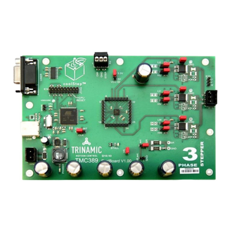
6TMC236 / TMC239 Evaluation Kit
Deelbögenkamp 4c,
D - 22 297 Hamburg, Germany
Phone +49-40-51 48 06 - 0,
FAX: +49-40-51 48 06 - 60
http://www.trinamic.com
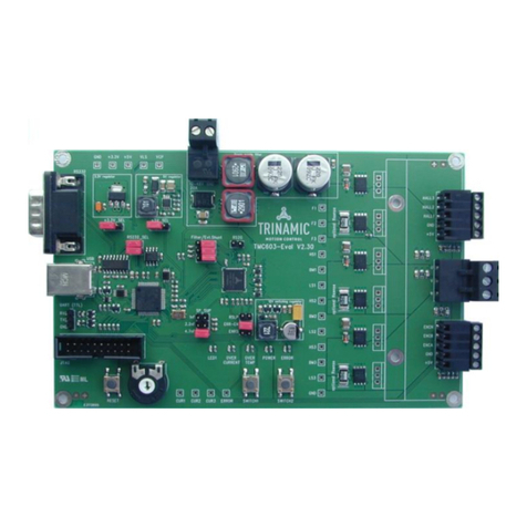
•Switch #1 (SPE): This switch controls the SPE (SPI enable) pin of the TMC236/TMC239. It must be in its
OFF position to enable control via SPI. Switching it ON selects analogue control mode.
•Switch #2 (EN): This switch controls the ENABLE pin of the TMC236/TMC239. It must be in the ON
position to enable the motor power. Otherwise the motor will not be powered.
•Switch #3 and #4 (BL2 and BL1): These switches control the BL2 and BL1 pin of the TMC236/TMC239 and
so control the blank time. See the TMC236 or TMC239 data sheet for details.
•TSlope: This potentiometer is connected to the SLP pin of the motor driver chips and so controls the slope
time. Turn it left to achieve a faster slope resulting in a lower heat dissipation, or turn it right to get a slower
slope resulting in a higher heat dissipation. A slower slope requires a higher blank time setting (BL1 and BL2
switches). Please see the TMC236 or TMC239 data sheet for details.
2.3 LEDs on the board
The board is equipped with LEDs that show the error flags of the TMC236 or TMC239 stepper motor driver. Their
meanings are as follows:
•OC A: Overcurrent on output A: There is too much current on coil output A, maybe caused by a short circuit.
•OC B: Overcurrent on output B: There is too much current on coil output B, maybe caused by a short circuit.
•OL A: Open load on output A: The coil output A is not connected to a motor coil. This error also occurs when
the step frequency is high and the supply voltage too low.
•OL B: Open load on output B: The coil output B is not connected to a motor coil. This error also occurs when
the step frequency is high and the supply voltage too low.
•OC HS: Overcurrent on high side.
•UV: Undervoltage: The supply voltage is too low for the driver to operate properly.
•OT PW: Overtemperature pre-warning: The temperature of the driver is getting too high.
•OT: Overtemperature: The temperature of the driver is too high so that the driver has switched off and will
switch on again when the temperature is getting lower.
•Error: Error in analogue mode.
2.4 Technical data
•TMC236 evaluation board:
•Power supply: 7..28.5V DC
•Maximum coil current:
•with RA2 and RB2 jumpers open: 680mA
•with RA2 and RB2 jumpers closed: 1250mA
•Usable motors: two phase bipolar stepper motors
•RS232 interface: 9600 bps, 8 data bits, no parity bit, one stop bit
•TMC239 evaluation board:
•Power supply: 7..28.5V DC
•Maximum coil current:
•with RA2 and RB2 jumpers open: 950mA
•with RA2 and RB2 jumpers closed: 1700mA
•Usable motors: two phase bipolar stepper motors
•RS232 interface: 9600 bps, 8 data bits, no parity bit, one stop bit
Note: Due to the to the PCB trace resistance of about 0.02 Ohms there is a difference between the theoretical and
the real maximum coil current values. The values given above are the real values.


