TMC332 Evaluation Board Manual (V. 2.10 / January 8, 2010) 12
Copyright © 2010 TRINAMIC Motion Control GmbH & Co. KG
8Quick start
8.1 Connections
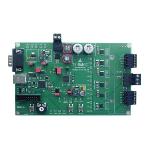
First connect the motor to connector J2 or J3, use pins 1, 2 and 3 for three phase motors, pin 4
remains unconnected in this case. The firmware on the board is designed for a QMot QSH-4218-41-10-
035 two phase stepper motor or a JapanServo KT42JM06-551 three phase stepper motor operated at
24V supply voltage. Other motors, especially ones with lower phase resistance may draw more current
when switching on the evaluation board. For such motors another way of starting the board,
described under 8.4, should be used and the motor should be left disconnected in this place.
Next connect an RS232 null modem cable from a serial port or a USB to serial converter to the RS232
connector X1001.
Now connect a DC power supply with 24V (15V to 36V are allowed but may result in bad performance
or too high motor current) to either J1 or J7 and turn it on.
When using a three phase motor, press S1 once to switch to three phase motor mode (the red LED
turns off).
8.2 Control via S1, S2, S3 and the potentiometer
The basic functions can be controlled with the on board controls. After power on, the board is in two
phase motor (red LED on) positioning mode (green LED flashing fast) with a PWM amplitude of 31 and
no current regulation. The potentiometer is used to preset a position, the motor drives to. Button S2
can be used to switch between two positioning speeds.
With button S1 the board can be set to three phase motor mode (red LED turned off).
Button S3 steps through the three operating modes, from positioning mode to velocity mode (green
LED flashes slower), where the potentiometer controls the velocity of the motor and button S2 can
toggle the direction using the sign of the velocity, not the shaft input.
From velocity mode, S3 steps to stop mode (green LED flashes very slow), where the motor is stopped
and the two TMC603 can be disabled and enabled with button S2. From there, S3 changes to
positioning mode again.
8.3 Starting the software
Start the evaluation software (Eval428_332.exe), select the COM port, the board is connected to and
click “Open”. Then click the “TMC332…” button that appeared to get the window shown in Figure 2.
Now the settings of the TMC332 and also some functions on the evaluation board are accessible.
8.4 Connection of special motors (low phase resistance)
When the board is powered up without a motor connected and the software is started, it takes
some steps to connect the motor safely.
- Uncheck the checkbox “TMC603 Enable”
- Select the radiobutton “PWM_AMPL”, check the checkbox “Modulation”, set the value “PWM:” to
0 and click “Send SPI Telegram”
- Connect the motor to the evaluation board
- Check the checkbox “TMC603 Enable”
- Raise the value “PWM:” to a value for normal operation (the calculations of the phase current
values are shown in the TMC332 manual). Changes have to be sent with “Send SPI Telegram”.
Alternatively the current regulator can be set up directly.
- continue to use the board normally
8.5 Using the TMC457-EVAL as Step/Direction signal generator
To use the TMC457-EVAL board to generate the Step and Direction signals, the SCS_S Jumper (section
5.2) has to be removed to disable signal evaluation from the TMC428. Three wires connect the two
boards, using connector X2 on the TMC457-EVAL board and connector J8 on the TMC332-EVAL board.
On X2 of the TMC457-EVAL board, Pin 1 (DIR), 2 (STEP) and 6 (GND) are connected to the corresponding
pins of J8 on the TMC332-EVAL board.
For proper pulse recognition, the width of the step pulses must be at least one clock cycle of the
TMC332. Since the two boards are running on two different crystals, the pulse width in the TMCL
program on the TMC457-EVAL board should be set to 2, this is achieved by setting the axis parameter
64 to 2:
SAP 64, 0, 2


