Trio Datacom ER450 User manual

Page 1
E Series Data Radio – User Manual
www.triodatacom.com Issue 11: Jun 2009
User Manual
E Series Data Radio
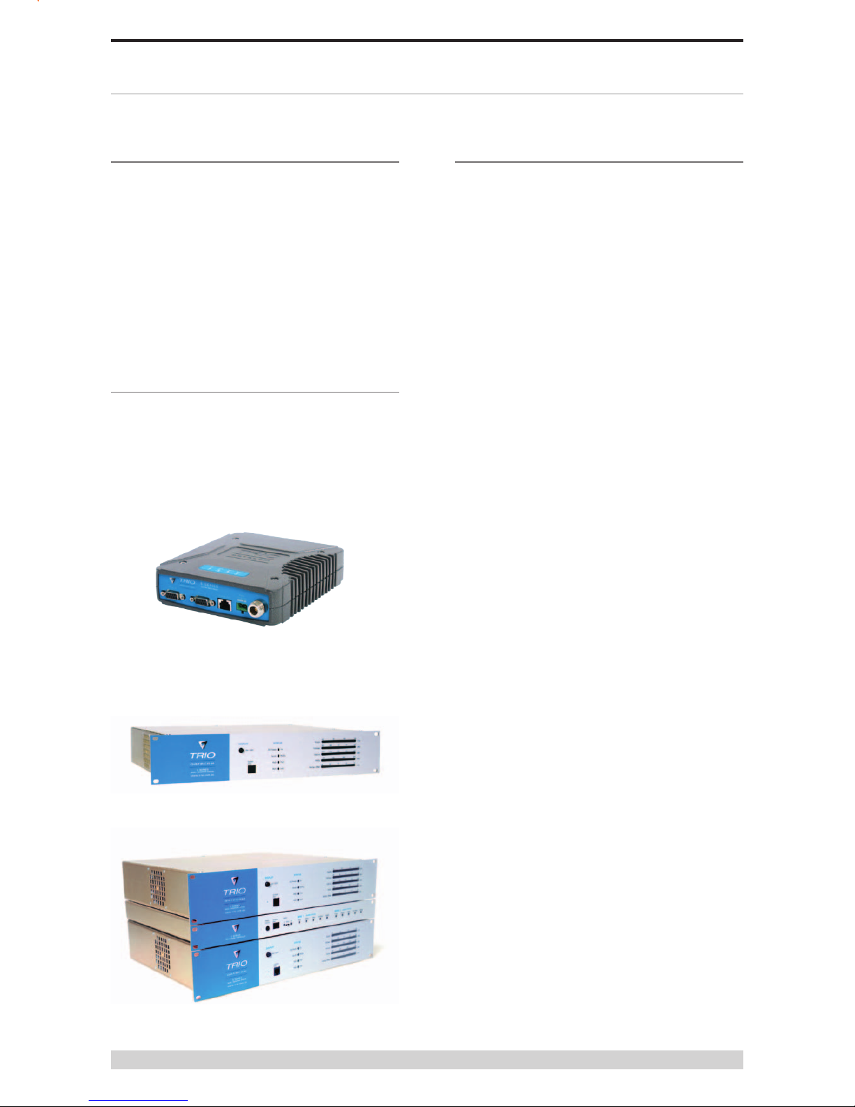
ER450 Remote Data Radio
EB450 Base Station
EH450 Hot Standby Base Station

Page 2
E Series Data Radio – User Manual
Part I – TVIEW+ Management Suite -
Programmer 42
Introduction 42
Installation 42
TVIEW+ Front Panel 43
Programmer 43
Appendix A - Firmware Updates 55
Part J – Specifications 57
Part K – Support Options 60
Website Information 60
E-mail Technical Support 60
Telephone Technical Support 60
Service Department 60
Contents
SECTION 1 3
Part A – Preface 4
Warranty 4
Important Notice 4
Compliance Information 5
Warning - RF Exposure 5
Related Products 6
Other Related Documentation and Products 6
Revision History 6
Part B – E Series Overview 7
Denition of E Series Data Radio 7
E Series Product Range 7
E Series – Features and Benets 7
Model Number Codes 9
Standard Accessories 10
Part C – Applications 11
Application Detail 11
Systems Architecture 12
Part D – System Planning and Design 14
Selecting Antennas 14
Understanding RF Path Requirements 14
Examples of Predictive Path Modelling 15
Data Connectivity 18
Power Supply and Environmental Considerations 21
Physical Dimensions - Remote Data Radio - ER450 22
Physical Dimensions - Base Station - EB450 23
Physical Dimensions - Hot Standby Base Station - EH450 24
Part E – Getting Started 25
ER450 Quick Start Guide 25
EB450 Quick Start Guide 31
EH450 Quick Start Guide 34
Part F - Operational Features 39
Multistream functionality (SID codes) 39
Collision Avoidance (digital and RFCD based) 39
Digipeater Operation 39
TVIEW+ Diagnostics 39
Poor VSWR Sensing 39
Part G – Commissioning 40
Power-up 40
LED Indicators 40
Data Transfer Indications 40
Antenna Alignment and RSSI Testing 40
Link Establishment and BER Testing 40
VSWR Testing 40
Part H – Maintenance 41
Routine Maintenance Considerations 41

Page 3
E Series Data Radio – User Manual
SECTION 1
Part A - Preface
Part B - E Series Overview
Part C - Applications
Part D - System Planning and Design
Part E - Getting Started
Part F - Operational Features
Part G - Commissioning
Part H - Maintenance

Page 4
E Series Data Radio – User Manual
Warranty
All equipment supplied by Trio DataCom Pty Ltd is warranteed
against faulty workmanship and parts for a period of twelve (12)
months from the date of delivery to the customer. During the
warranty period Trio DataCom Pty Ltd shall, at its option, repair
or replace faulty parts or equipment provided the fault has not
been caused by misuse, accident, deliberate damage, abnormal
atmosphere, liquid immersion or lightning discharge; or where
attempts have been made by unauthorised persons to repair or
modify the equipment.
The warranty does not cover modications to software. All
equipment for repair under warranty must be returned freight paid
to Trio DataCom Pty Ltd or to such other place as Trio DataCom
Pty Ltd shall nominate. Following repair or replacement the
equipment shall be returned to the customer freight forward. If it is
not possible due to the nature of the equipment for it to be returned
to Trio DataCom Pty Ltd, then such expenses as may be incurred
by Trio DataCom Pty Ltd in servicing the equipment in situ shall be
chargeable to the customer.
When equipment for repair does not qualify for repair or
replacement under warranty, repairs shall be performed at the
prevailing costs for parts and labour. Under no circumstances shall
Trio DataCom Pty Ltd’s liability extend beyond the above nor shall
Trio DataCom Pty Ltd, its principals, servants or agents be liable
for the consequential damages caused by the failure or malfunction
of any equipment.
Important Notice
© Copyright 2005 Trio DataCom Pty Ltd All Rights Reserved
This manual covers the operation of the E Series of Digital Data
Radios. Specications described are typical only and are subject to
normal manufacturing and service tolerances.
Trio DataCom Pty Ltd reserves the right to modify the equipment,
its specication or this manual without prior notice, in the interest
of improving performance, reliability or servicing. At the time of
publication all data is correct for the operation of the equipment
at the voltage and/or temperature referred to. Performance data
indicates typical values related to the particular product.
This manual is copyright by Trio DataCom Pty Ltd. All rights
reserved. No part of the documentation or the information supplied
may be divulged to any third party without the express written
permission of Trio DataCom Pty Ltd.
Same are proprietary to Trio DataCom Pty Ltd and are supplied
for the purposes referred to in the accompanying documentation
and must not be used for any other purpose. All such information
remains the property of Trio DataCom Pty Ltd and may not be
reproduced, copied, stored on or transferred to any other media or
used or distributed in any way save for the express purposes for
which it is supplied.
Products offered may contain software which is proprietary to Trio
DataCom Pty Ltd. However, the offer of supply of these products
and services does not include or infer any transfer of ownership
of such proprietary information and as such reproduction or reuse
without the express permission in writing from Trio DataCom Pty
Ltd is forbidden. Permission may be applied for by contacting Trio
DataCom Pty Ltd in writing.
Part A - Preface
Part A – Preface

Page 5
E Series Data Radio – User Manual
R&TTE Notice (Europe)
Applies to models Ex450-xxExx-xxx
In order to comply with the R&TTE (Radio & Telecommunications
Terminal Equipment) directive 1999/5/EC Article 3 (Low Voltage
Directive 73/23/EEC), all radio modem installations must include an
external in-line lightning arrestor or equivalent device that complies
with the following specications:
• DC Blocking Capability - 1.5kV impulse (Rise Time 10mS,
Fall Time 700mS) (Repetition 10 Times) or 1.0kV rms 50Hz
sine wave for 1 minute.
Trio Datacom declares that the E Series radio modem is in
compliance with the essential requirements and other relevant
provisions of the Directive 1999/5/EC. Therefore Trio Datacom E
Series equipment is labelled with the following CE-marking.
0889
Part A - Preface
Compliance Information
Warning - RF Exposure
The radio equipment described in this user manual emits low level
radio frequency energy. The concentrated energy may pose a
health hazard depending on the type of antenna used. In the case
of:
Non-directional antenna - DO NOT allow people to come within 0.5
metres (20 inches) of the antenna when the transmitter is operating
Directional antenna - DO NOT allow people to come within 6
metres (20 feet) of the antenna when the transmitter is operating.
FCC Notice (Hot Standby Controller Only)
This equipment has been tested and found to comply with the
limits for a Class B digital device, pursuant to Part 15 of the FCC
Rules. These limits are designed to provide reasonable protection
against harmful interference in a residential installation. This
equipment generates, uses, and can radiate radio frequency
energy and, if not installed and used in accordance with the
instruction, equipment may cause harmful interference to radio
communications. However, there is no guarantee that interference
will not occur in a particular installation. If this equipment does
cause harmful interference to radio or television reception, which
can be determined by turning the equipment off and on, the user is
encouraged to try to correct the interference by one or more of the
following measures:
• Re-orient to relocate the receiving antenna.
• Increase the separation between the equipment and
receiver.
• Connect the equipment into an outlet on a circuit different to
that which the receiver is connected.
• Consult the dealer or an experienced radio/television
technician for assistance.
IC Notice (Hot Standby Controller Only)
This Class B digital apparatus complies with Canadian ICES-003.
Cet appariel numerique de la class B est conforme a la norme
NBM-003 du Canada.

Page 6
E Series Data Radio – User Manual
WEEE Notice (Europe)
This symbol on the product or its packaging indicates that this
product must not be disposed of with other waste. Instead, it is
your responsibility to dispose of your waste equipment by handing
it over to a designated collection point for the recycling of waste
electrical and electronic equipment. The separate collection and
recycling of your waste equipment at the time of disposal will help
conserve natural resources and ensure that it is recycled in a
manner that protects human health and the environment. For more
information about where you can drop off your waste equipment
for recycling, please contact the dealer from whom you originally
purchased the product.
Dieses Symbol auf dem Produkt oder seinem Verpacken
zeigt an, daß dieses Produkt nicht mit anderer Vergeudung
entledigt werden darf. Stattdessen ist es Ihre Verantwortlichkeit,
sich Ihre überschüssige Ausrüstung zu entledigen, indem es
rüber sie zu einem gekennzeichneten Ansammlungspunkt
für die Abfallverwertung elektrische und elektronische
Ausrüstung übergibt. Die unterschiedliche Ansammlung und
die Wiederverwertung Ihrer überschüssigen Ausrüstung zu der
Zeit der Beseitigung helfen, Naturresourcen zu konservieren
und sicherzugehen, daß es in gewissem Sinne aufbereitet wird,
daß menschliche Gesundheit und das Klima schützt. Zu mehr
Information ungefähr, wo Sie weg von Ihrer überschüssigen
Ausrüstung für die Wiederverwertung fallen können, treten Sie
bitte mit dem Händler in Verbindung, von dem Sie ursprünglich das
Produkt kauften.
Related Products
ER450 Remote Data Radio
MR450 Remote Data Radio
EB450 Base/Repeater Station
EH450 Hot Standby Base Station
Other Related Documentation
and Products
E Series Quick Start Guides
TVIEW+ Management Suite
Digital Orderwire Voice Module (EDOVM)
Multiplexer Stream Router (MSR)
Revision History
Issue 5 February 2004 Additional radio and programmer
information
Issue 6 February 2005 Additional information for
Hazardous Locations.
Issue 7 May 2005 Various Updates
Issue 8 Jan 2006 WEEE Updates
Issue 9 Mar 2006 E Series Gen II Updates
Issue 10 Mar 2007 Order Matrix Updated
Issue 11 Jun 2009 Minor Fixes.
Important Notices for Class I, Division 2,
Groups A, B, C & D Hazardous Locations
Applies to models ER450-xxxxx-xHx(CSA Marked)
This product is available for use in Class I, Division 2, Groups
A, B, C & D Hazardous Locations. Such locations are dened in
Article 500 of the US National Fire Protection Association (NFPA)
publication NFPA 70, otherwise known as the National Electrical
Code and in Section 18 of the Canadian Standards Association
C22.1 (Canadian Electrical Code).
The transceiver has been recognised for use in these hazardous
locations by the Canadian Standards Association (CSA)
International. CSA certication is in accordance with CSA Standard
C22.2 No. 213-M1987 and UL Standard 1604 subject to the
following conditions of approval:
1. The radio modem must be mounted in a suitable enclosure so
that a tool is required to gain access for disconnection of antenna,
power and communication cables.
2. The antenna, DC power and interface cables must be routed
through conduit in accordance with the National Electrical Codes.
3. Installation, operation and maintenance of the radio modem
should be in accordance with the radio modem’s user manual and
the National Electrical Codes.
4. Tampering or replacement with non-factory components may
adversely affect the safe use of the radio modem in hazardous
locations and may void the approval.
5. A power connector retainer with thumbwheel screw as supplied
by Trio Datacom MUST be used.
WARNING EXPLOSION HAZARD
Do not disconnect equipment unless power has been
switched off or the area is known to be non-hazardous.
Substitution of components may impair suitability for
Class I, Division 2. Refer to Articles 500 through 502
of the National Electrical Code (NFPA 70) and Section
18 of CSA C22.1 for further information on hazardous
locations and approved Division 2 wiring methods.
Page 7
E Series Data Radio – User Manual
Part B – E Series Overview
Definition of E Series Data Radio
The E Series is a range of wireless modems designed for the
transmission of data communications for SCADA, telemetry
and any other information and control applications that utilise
ASCII messaging techniques. The E Series uses advanced
“digital” modulation and signal processing techniques to achieve
exceptionally high data throughput efciency using traditional
licensed narrow band radio channels.
These products are available in many frequency band and
regulatory formats, to suit spectrum bandplans, in various
continental regions. The range is designed for both xed point
to point (PTP), and multiple address (MAS) or point to multipoint
(PMP) systems.
E Series Product Range
The E Series range consists of the basic half duplex “Remote”
radio modem, an extended feature full duplex Remote radio
modem, and ruggedised Base Station variants, including an
optional Hot Standby controller to control two base station units in
a redundant conguration.
Frequency band variants are indicated by the band prex and
model numbering. (See Model Number Codes)
Part B – E Series Overview
E Series – Features and Benefits
Common Features and Benefits of the E
Series Data Radio (Generation II)
• Up to 19200bps over-air data rates using programmable
DSP based advanced modulation schemes.
• Designed to various International regulatory requirements
including FCC, ETSI and ACA.
• Superior receiver sensitivity.
• Fast data turnaround time <10mS.
• 128-bit AES encryption.
• Flash upgrade-able rmware – insurance against
obsolescence.
• Multi-function bi-colour Tx/Rx data LEDs showing Port
activity (breakout box style), as well as LEDs indicating Tx,
Rx, RF Signal, Data Synchronisation and DC Power status
of the radio.
• Rugged N type antenna connectors on all equipment.
• High temperature transmitter foldback protection.
• Two independent congurable data ports and separate
system port.
• Higher port speeds to support increased air-rate (up to
57600bps on Port A and 38400bps on Port B).
• Compatible with most industry standard data protocols. eg:
MODBUS, DNP-3, IEC 870, SEL Mirrored Bits, etc.
• Independent system port for interruption free programming
and diagnostics (in addition to two (2) user ports).
• 9600bps in 12.5 kHz radio channels with ETSI
specications.
• Compatible with legacy systems (Non Packet Digital and
Bell 202 Modes)
• Remote over-the-air conguration of any radio from any
location.
• Multistream™ simultaneous data streams allows for multiple
vendor devices / protocols to be transported on the one
radio network.
• Flexible data stream routing and steering providing optimum
radio channel efciency – complex data radio systems can
be implemented with fewer radio channels.
• The ability to duplicate data streams – that is, decode the
same off-air data to two separate ports.
• Multi-function radio capable of dropping off one stream to a
port and forward on or repeat (store and forward) the same
or other data.
• Stand-alone internal store and forward operation – buffered
store and forward operation even in the ER remote units.
ER450 Remote Radio
EB450 Base / Repeater Station
EH450 Hot Standby Base Station

Page 8
E Series Data Radio – User Manual
Part B – E Series Overview
• Unique integrated C/DSMA collision avoidance technology
permits simultaneous polling and spontaneous reporting
operation in the same system.
• Digital receiver frequency tracking for long term data
reliability.
• Network wide non intrusive diagnostics which runs
simultaneously with the application.
• Network wide diagnostics interrogation which can be
performed from anywhere in the system including any
remote site.
• Diagnostics will route its way to any remote or base /
repeater site regardless of how many base / repeater
stations are interconnected.
• Full range of advanced features available within Network
Management and Remote Diagnostics package – BER
testing, trending, channel occupancy, client / server
operation, etc.
• On board memory for improving user data latency
– increased user interface speeds.
• Full CRC error checked data – no erroneous data due to
squelch tails or headers.
• Radio utilises world standard HDLC as its transportation
protocol.
• Various ow control and PTT control mechanisms.
• Congurable backward compatibility with existing D Series
modulation scheme for use within existing networks.
• Digital plug in order wire option for commissioning and
occasional voice communications without the need to inhibit
users application data.
Features and Benefits of ER450 Remote
Data Radio
• Optional full duplex capable remote – separate Tx and Rx
ports for connection to an external duplexer.
• New compact and rugged die cast case with inbuilt
heatsink.
• Low power consumption with various sleep modes.
• Rugged N type antenna connectors.
• Data Port “breakout box” style ow LEDs for easier
troubleshooting.
Features and Benefits of EB450 Standard
Base / Repeater Station
• Competitively priced high performance base.
• Incorporates a rugged 5W power amplier module.
Features and Benefits of EH450 Hot Standby
Base / Repeater Station
• Individual and identical base stations with separate control
logic changeover panel.
• ALL modules are hot swapable without any user downtime.
• Flexible antenna options – single, separate Tx & Rx, two Tx
and two Rx.
• Both on-line and off-line units monitored regardless of active
status.
Page 9
E Series Data Radio – User Manual
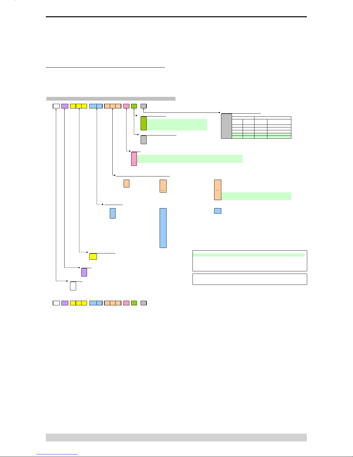
Model Number Codes
Part B – E Series Overview
D, E & M Series Data Radios - Part Number Matrix = Tyxxx-aabbb-cde
T y x x x -a a b b b -c d e
Options - Hot Standby Configurations*
Options - Base Stations 0= No Options
0Duplexer Antenna
1
5Number Type Antenna
Config Antenna Type
6 A - - - Separate Tx & Rx
AB- - Dual [x4] Separate Tx & Rx
CSingle Internal Single Combined Tx/Rx
Options - E and M Series Remotes DDual [x2] Internal Dual [x2] Combined Tx/Rx
0= No Options FDual [x2] External Dual [x2] Combined Tx/Rx
H
Options*
E= Diagnostics and Encryption - [DIAGS/E or DIAGS/EH] (E Series Only) ***
X= Full Duplex Operation and Diagnostics [ERFD450 & DIAGS/E] (ER450 only)
Y= Full Duplex Operation, Diagnostics and Encryption (ER450 only) ***
L= Low Power Module + Diagnostics (MR450 only)
D= Diagnostics
RF Channel Data Rate & Bandwidth (Internal Modem)
D Series E Series M Series~~
A01
= ACA 4800bps 12.5kHz
A01
000
A02
= ACA 9600bps 25kHz
A02
001
F01 = FCC 9600bps 12.5kHz F01 002
F02
003
E01
004
= Hazardous Environment Class 1, Div 2 and Diagnostics
Available ONLY and standard on ER & MR450-aa-000 to 004
= FCC 19k2bps 25kHz
= 450MHz Band Reject [DUPLX450BR]
= 900MHz Band Pass Compact [DUPLX900BPC]
= 900MHz Band Pass (76MHz split)[DUPLX852/930]
= ETSI 4800
#
/ 9600 bps 12.5kHz
= ACA 4800
#
/ 9600bps 12.5kHz
= No Options
= 450MHz 20W RF Power Output
= Analog Only 12.5kHz (Local Diags included - No Additional Charge)
= 2400bps 12.5KHz / 4800bps 25kHz
= 4800bps 12.5KHz / 9600bps 25kHz
= ACA 9600
#
/ 19k2bps 25kHz
= FCC 9600
#
/ 19K2bps 12.5kHz
= FCC 9600bps 12.5KHz
= ETSI 4800bps 12.5KHz
E01
004
241*
242*
482*
Frequency Bands
D Series (900MHz) E Series (400MHz) M Series (400MHz)
07
46
M
47 H
06
48
50
63
64
56
57
55
51
65
52
53 Note: Other frequency bands available on request
60
54
Generic Frequency Band NOTES:
450 = 370 to 518MHz (E & M Series only) * Additional charges apply. Must be ordered separately. Please refer to price list.
900 = 800 / 900MHz (D Series only) ** Consult factory for availability.
*** Export restrictions may apply.
#
Provides compatibility with D and/or M Series radios
Unit Type [ ] Items in [ ] parenthesis refer to actual Trio part numbers
R= Remote Station ~~ M Series Compatible EB/EH450 Base Stations are Type A01 or F01
B= Base / Repeater Station (D, E & M Series Only)
H= Hot Standby Base / Repeater (D, E & M Series Only) Standards: ACA - Australian Communications Authority
FCC - Federal Communications Commission
Model Type ETSI - European Telecommunication Standards Institute
D= D Series Family
E= E Series Family
M
= M Series Family
= 418 to 435MHz (Tx & Rx)
= 428 to 444MHz (Tx & Rx)
= 436 to 450MHz (Tx & Rx)
= 450 to 465MHz (Tx & Rx)
= 455 to 470MHz (Tx & Rx)
= 395 to 406MHz (Tx & Rx)
= 465 to 480MHz (Tx & Rx)
= 403 to 417MHz (Tx & Rx)
= (Tx) 923 to 933MHz (1W)
(Rx) 847 to 857MHz (Full Duplex)
= (Tx) 847 to 857MHz (1W)
(Rx) 923 to 933MHz (Full Duplex)
= 450 to 520MHz (Tx & Rx) (M Series Only)
= 400 to 470MHz (Tx & Rx) (M Series Only)
= 2400bps 25KHz (S Series [24SR]* Compatible) c/w Local Diags
= 490 to 500MHz (Tx & Rx)
= 4800bps 25KHz (S Series [48SR]* Compatible) c/w Local Diags
= ETSI 4800
#
/ 9600 bps 12.5kHz
= 505 to 518MHz (Tx & Rx)
= 370 to 388MHz (Tx & Rx)
= 380 to 396MHz (Tx & Rx)
= 406 to 421MHz (Tx & Rx)
= 415 to 430MHz (Tx & Rx)
= 480 to 494MHz (Tx & Rx)
= 2400bps 12.5KHz (S Series [24SR]* Compatible) c/w Local Diags
= ETSI 4800bps 12.5KHz
M
= M Series Family
Example:
E R 4 5 0 -5 1 A 0 2 -D H 0
Dwg / Ver: 184-56-0000-F
The example shown specifies: E Series, Remote Radio, generic 450MHz band, with a specific
frequency of 450MHz to 465MHz, a 9600/19200bps modem, with a bandwidth of 25kHz, diagnostics
and Class 1, Div 2 Hazardous Approval (standard).

Page 10
E Series Data Radio – User Manual
Part B – E Series Overview
Part Number Description
Duplexers
DUPLX450BR Duplexer BAND REJECT 400-520 MHz for
use with Base / Repeater / Links. For Tx / Rx
frequency splits >9MHz. (Fitted Externally
for a Link, Internally or Externally for Base /
Repeater)
DUPLX450PC Duplexer BAND REJECT 400-520 MHz for
use with Base / Repeater / Links. For Tx / Rx
frequency splits <9MHz. (Fitted Externally
for a Link, Internally or Externally for Base /
Repeater)
DUPLX450BP Duplexer PSEUDO BAND PASS Cavity 400-
520 MHz for External use with Base / Repeater
/ Links.
Notes:
1. Frequencies must be specied at time of order.
2. Interconnecting (Feeder Tail) cables must be ordered
separately for Externally tted Duplexers.
Antennas
ANT450/9A Antenna Yagi 6 Element 9dBd Aluminium 400-
520 MHz c/w mtg clamps
ANT450/9S Antenna Yagi 6 Element 9dBd S/Steel 400-520
MHz c/w mtg clamps
ANT450/13A Antenna Yagi15 Element 13dBd Aluminium 400-
520 MHz c/w mtg clamps.
ANT450/13S Antenna Yagi 15 Element 13dBd S/Steel 400-
520 MHz c/w mtg clamps.
ANTOMNI/4 Antenna Omnidirectional Unity Gain Side Mount
Dipole 400-520 MHz c/w galv. clamp
ANT450/D/N Antenna Omnidirectional Unity Gain Ground
Independent Dipole 400-520 MHz c/w 3m
cable, mounting bracket & N connector
ANT450/6OM Antenna Omnidirectional 6dBd 400-520 MHz
c/w mtg clamps
ANT450/9OM Antenna Omnidirectional 9dBd 400-520 MHz
c/w mtg clamps
Note:
1. Frequencies must be specied at time of order.
Power Supplies
PS13V82A Power Supply 13.8V 2A 240VAC
PS13V810A Power Supply Switch Mode 240VAC 13.8V 10A
for Base Stations – Battery Charge Capability
Part Number Description
RF Cables and Accessories
NM/NM/TL23 Feeder Tail - N Male to N Type Male 50cm fully
sweep tested RG-223
NM/NM/TLL23 Feeder Tail - N Male to N Type Male 1 metre
fully sweep tested RG-223
RFCAB5M 5.0m RG-58 type Antenna Feeder Cable
terminated with N type Male Connectors
RFCAB5M2 5.0m RG-213 type Antenna Feeder Cable
terminated with N type Male Connectors
RFCAB10M 10.0m RG-213 type Antenna Feeder Cable
terminated with N type Male Connectors
RFCAB20M 20.0m RG-213 type Antenna Feeder Cable
terminated with N type Male Connectors
RFCAB20M4 20.0m LDF4-50 type (1/2” foam dialectric)
Antenna Feeder Cable terminated with N type
Male Connectors
LGHTARRST Lightning Surge Arrestor In-line N Female to N
Female
Multiplexers
MSR/9 Multiplexer/Stream Router – 9 Port with RS-232
I/faces, Manual and software.
Network Management Diagnostics
DIAGS/E Network Management and Remote Diagnostics
Facilities per Radio – E Series
DIAGS/EH Network Management and Remote Diagnostics
Facilities – E Series for EH450
Software
TVIEW+ Conguration, Network Management and
Remote Diagnostics Software
TVIEW+ESeries E Series Programming Cable and conguration
software.
Other
EDOVM Digital Order Wire Voice Module
ERFD450 ER450…. Conversion to Full Duplex Operation
(N Type – Tx Port, SMA - Type Rx Port)
Note: Requires external duplexer
ERFDTRAY 19” Rack Tray for Mounting of ER450 Full
Duplex Radio and External Band Reject
Duplexer
Standard Accessories

Page 11
E Series Data Radio – User Manual
Part C – Applications
Part C – Applications
Generic Connectivity
The E Series has been designed for SCADA and telemetry
applications, and any other applications that use an ASCII
communications protocol, and which connect physically using the
RS232 interface standard (although converters can be used to
adapt other interfaces such as RS422/485, RS530/V35, G703 etc).
Any protocol that can be displayed using a PC based terminal
program operating via a serial communications port is suitable for
transmission by the E Series radio modems.
An ASCII protocol is any that consists of message strings formed
from ASCII characters, that being dened as a 10 or 11 bit block
including start and stop bits, 7 or 8 data bits and optional parity
bit(s). Port set-up dialog that includes the expressions “N,8,1”, or
E,7,2” or similar indicate an ASCII protocol.
Most of the dominant telemetry industry suppliers utilise proprietary
ASCII protocols, and also common ‘open standard” industry
protocols such as DNP3, MODBUS, TCP/IP, and PPP. These are
all ASCII based protocols.
Industries and Applications
The E Series products are widely used in point-to-point and
point-to-multipoint (multiple access) applications for remote
interconnection of PLCs, RTUs, dataloggers, and other data
monitoring and control devices - including specialist utility devices
(such as powerline ACRs). In addition, other applications such as
area wide security and alarm systems, public information systems
(trafc ow and public signage systems) and environmental
monitoring systems.
Application Detail
SCADA Systems
This is where one or more centralised control sites are used
to monitor and control remote eld devices over wide areas.
Examples include regional utilities monitoring and controlling
networks over entire shires or a greater city metropolis. Industry
sectors include energy utilities (gas and electricity distribution),
water and sewerage utilities, catchment and environment groups
(rivers, dams and catchment management authorities).
Telemetry Systems
Dedicated telemetry control systems interconnecting sequential
devices either where cabling is not practical or distances are
considerable.
Examples include:
• ore conveyor or slurry pipeline systems
• water systems (pump and reservoir interlinking)
• broadcast industry (linking studio to transmitter) etc.

Page 12
E Series Data Radio – User Manual
Part C – Applications
Systems Architecture
Point-to-Point
This simple system architecture provides a virtual connection
between the two points, similar to a cable. Dependent of the
hardware chosen, it is possible to provide a full duplex connection
(i.e. data transfer in both directions simultaneously) if required.
Point-to-Multipoint Systems
In a multiple access radio system, messages can be broadcast
from one (master) site to all others, either using a half duplex radio
system or from any site to all others, using a simplex radio channel.
Half duplex systems often utilise a full duplex master, to make the
system simpler and for faster operation.
In either case, it will be necessary for the application to support
an addressing system, since
the master needs to be able
to select which remote device
it with which it wishes to
communicate. Normally, the radio
system is allowed to operate
“transparently”, allowing the
application’s protocol to provide
the addressing, and thus control
the trafc. Where the application
layer does not provide the
addressing, the E Series can
provide it using SID codes™.

Page 13
E Series Data Radio – User Manual
Part C – Applications
(See Part F - Operational Features)
Digipeater Systems
This conguration is used where all sites are required to
communicate via a repeater site. A repeater site is used because it
has a position and/or height advantage and thus provides superior
or extended RF coverage. The radio modem at the repeater does
not have to be physically connected to the application’s master
site. Information from the application’s master is transmitted to the
repeater via radio, and the repeater then relays this information
to the other eld sites. In this scenario, the repeater is the master
from an RF point of view, and the application master is effectively a
“remote” from an RF point of view, even though it is controlling the
data transfer on the system.
Backbone Store and Forward Systems
Store and forward is used as a way of extending RF coverage by
repeating data messages from one site to another.
This can be done globally using the inbuilt data repeating functions,
or selectively using intelligent address based routing features
available in some PLC/RTU protocols.
In this case it is necessary for all units on the system to operate
in half duplex mode (only key-up when transmitting data), so that
each site is free to hear received signals from more than one
source.
Digipeater System
Backbone Store and Forward System

Page 14
E Series Data Radio – User Manual
Part D – System Planning and Design
Part D – System Planning and Design
Selecting Antennas
Understanding RF Path
Requirements
A radio modem needs a minimum amount of received RF signal to
operate reliably and provide adequate data throughput.
In most cases, spectrum regulatory authorities will also dene
or limit the amount of signal that can be transmitted, and the
transmitted power will decay with distance and other factors, as it
moves away from the transmitting antenna.
It follows, therefore, that for a given transmission level, there will
be a nite distance at which a receiver can operate reliably with
respect to the transmitter.
Apart from signal loss due to distance, other factors that will decay
a signal include obstructions (hills, buildings, foliage), horizon
(effectively the bulge between two points on the earth), and (to
a minimal extent at UHF frequencies) factors such as fog, heavy
rain-bursts, dust storms, etc.
In order to ascertain the available RF coverage from a transmitting
station, it will be necessary to consider these factors. This can be
done in a number of ways, including
(a) using basic formulas to calculate the theoretically available
signal - allowing only for free space loss due to distance,
(b) using sophisticated software to build earth terrain models
and apply other correction factors such as earth curvature
and the effects of obstructions, and
(c) by actual eld strength testing.
It is good design practice to consider the results of at least two of
these models to design a radio path.

Page 15
E Series Data Radio – User Manual
Part D – System Planning and Design
Examples of Predictive Path
Modelling
Clear line of site
Radio path with good signal levels, attenuated only by free space
loss.
Obstructed Radio Path
This path has an obstruction that will seriously degrade the signal
arriving at the eld site.
obstpath.pl3
Major Repeater Site
Field Site
Elevation (m)
703.83
309.67
Latitude
030 43 55.92 S
030 56 24.00 S
Longitude
150 38 49.51 E
150 38 48.00 E
Azimuth
180.10
0.10
Antenna Type
ANT450/6OM
ANT450/9AL
Antenna Height (m)
40.00
5.00
Antenna Gain (dBi)
8.15
11.15
Antenna Gain (dBd)
6.00
9.00
TX Line Type
LDF4-50
LDF4-50
TX Line Length (m)
40.00
5.00
TX Line Unit Loss (dB/100 m)
6.79
6.79
TX Line Loss (dB)
2.72
0.34
Connector Loss (dB)
2.00
2.00
Frequency (MHz)
450.00
Path Length (km)
23.04
Free Space Loss (dB)
112.78
Diffraction Loss (dB)
16.71
Net Path Loss (dB)
117.25
117.25
Radio Type Model
EB450
ER450
TX Power (watts)
5.00
1.00
TX Power (dBW)
6.99
0.00
Effective Radiated Power (watts)
6.71
4.63
Effective Radiated Power (dBW)
8.27
6.66
RX Sensitivity Level (uv)
0.71
1.26
RX Sensitivity Level (dBW)
-140.00
-135.00
RX Signal (uv)
9.70
21.70
RX Signal (dBW)
-117.25
-110.26
RX Field Strength (uv/m)
95.74
115.23
Fade Margin (dB)
22.75
24.74
Raleigh Service Probability (%)
99.470
99.665
goodpath.pl3
Major Repeater Site
Field Site
Elevation (m)
756.69
309.67
Latitude
031 04 37.49 S
030 56 24.00 S
Longitude
150 57 26.34 E
150 38 48.00 E
Azimuth
297.05
117.21
Antenna Type
ANT450/6OM
ANT450/9AL
Antenna Height (m)
40.00
5.00
Antenna Gain (dBi)
8.15
11.15
Antenna Gain (dBd)
6.00
9.00
TX Line Type
LDF4-50
LDF4-50
TX Line Length (m)
40.00
5.00
TX Line Unit Loss (dB/100 m)
6.79
6.79
TX Line Loss (dB)
2.72
0.34
Connector Loss (dB)
2.00
2.00
Frequency (MHz)
450.00
Path Length (km)
33.33
Free Space Loss (dB)
115.99
Diffraction Loss (dB)
0.00
Net Path Loss (dB)
103.75
103.75
Radio Type Model
EB450
ER450
TX Power (watts)
5.00
1.00
TX Power (dBW)
6.99
0.00
Effective Radiated Power (watts)
6.71
4.63
Effective Radiated Power (dBW)
8.27
6.66
RX Sensitivity Level (uv)
0.71
1.26
RX Sensitivity Level (dBW)
-140.00
-135.00
RX Signal (uv)
45.93
102.70
RX Signal (dBW)
-103.75
-96.76
RX Field Strength (uv/m)
453.14
545.42
Fade Margin (dB)
36.25
38.24
Raleigh Service Probability (%)
99.976
99.985
Page 16
E Series Data Radio – User Manual
Part D – System Planning and Design
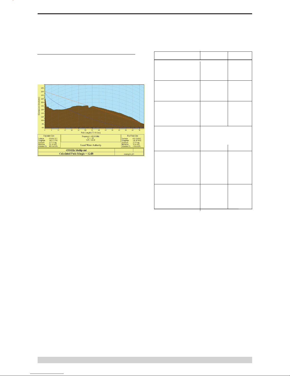
Effect of Earth Curvature on Long Paths
This path requires greater mast height to offset the earth curvature
experienced at such a distance (73km).
longpath.pl3
Repeater Site
Far Field Site
Elevation (m)
221.26
75.58
Latitude
032 01 21.63 S
032 33 00.00 S
Longitude
142 15 19.26 E
141 47 00.00 E
Azimuth
217.12
37.37
Antenna Type
ANT450/6OM
ANT450/9AL
Antenna Height (m)
40.00
5.00
Antenna Gain (dBi)
8.15
11.15
Antenna Gain (dBd)
6.00
9.00
TX Line Type
LDF4-50
LDF4-50
TX Line Length (m)
40.00
5.00
6.79
6.79
TX Line Loss (dB)
2.72
0.34
Connector Loss (dB)
2.00
2.00
Frequency (MHz)
450.00
Path Length (km)
73.46
Free Space Loss (dB)
122.85
Diffraction Loss (dB)
22.94
Net Path Loss (dB)
133.55
133.55
Radio Type Model
EB450
ER450
TX Power (watts)
5.00
1.00
TX Power (dBW)
6.99
0.00
Effective Radiated Power (watts)
6.72
4.64
Effective Radiated Power (dBW)
8.27
6.66
RX Sensitivity Level (uv)
0.71
1.26
RX Sensitivity Level (dBW)
-140.00
-135.00
RX Signal (uv)
1.49
3.32
RX Signal (dBW)
-133.55
-126.56
RX Field Strength (uv/m)
14.65
17.64
Fade Margin (dB)
6.45
8.44
Raleigh Service Probability (%)
79.735
86.656

Page 17
E Series Data Radio – User Manual
Part D – System Planning and Design
By compressing the transmission energy into a disc or beam, the
antenna provides more energy (a stronger signal) in that direction,
and thus is said to have a performance “gain” over a basic omni
antenna. Gain is usually expressed in dBd, which is referenced
to a standard folded dipole. Gain can also be expressed in dBi,
which is referenced to a theoretical “isotropic” radiator. Either way,
if you intend to send and receive signals from a single direction,
there is advantage in using a directional antenna - both due to
the increased signal in the wanted direction, and the relatively
decreased signal in the unwanted direction (i.e. “interference
rejection” properties).
Tuning the Antenna
Many antennas are manufactured for use over a wide frequency
range. Typical xed use antennas such as folded dipoles and yagis
are generally supplied with the quoted gain available over the
entire specied band range, and do not require tuning. Co-linear
antennas are normally built to a specic frequency specied when
ordering.
With mobile “whip” type antennas, it is sometimes necessary
to “tune” the antenna for the best performance on the required
frequency. This is usually done by trimming an antenna element
whilst measuring VSWR, or simply trimming to a manufacturer
supplied chart showing length vs frequency. These antennas would
normally be supplied with the tuning information provided.
Antenna Placement
When mounting the antenna, it is necessary to consider the
following criteria:
The mounting structure will need to be solid enough to withstand
additional loading on the antenna mount due to extreme wind, ice
or snow (and in some cases, large birds).
For omni directional antennas, it is necessary to consider the
effect of the mounting structure (tower mast or building) on the
radiation pattern. Close in structures, particularly steel structures,
can alter the radiation pattern of the antenna. Where possible,
omni antennas should always be mounted on the top of the mast
or pole to minimise this effect. If this is not possible, mount the
antenna on a horizontal outrigger to get it at least 1-2m away from
the structure. When mounting on buildings, a small mast or pole
(2-4m) can signicantly improve the radiation pattern by providing
clearance from the building structure.
For directional antennas, it is generally only necessary to consider
the structure in relation to the forward radiation pattern of the
antenna, unless the structure is metallic, and of a solid nature.
In this case it is also prudent to position the antenna as far away
from the structure as is practical. With directional antennas, it is
also necessary to ensure that the antenna cannot move in such
a way that the directional beamwidth will be affected. For long
yagi antennas, it is often necessary to install a breglass strut to
stablilise the antenna under windy conditions.
Alignment of Directional Antennas
This is generally performed by altering the alignment of the
antenna whilst measuring the received signal strength. If the signal
is weak, it may be necessary to pre-align the antenna using a
compass, GPS, or visual or map guidance in order to “nd” the
wanted signal. Yagi antennas have a number of lower gain “lobes”
centred around the primary lobe. When aligning for best signal
strength, it is important to scan the antenna through at least 90
degrees, to ensure that the centre (strongest) lobe is identied.
When aligning a directional antenna, avoid placing your hands or
body in the vicinity of the radiating element or the forward beam
pattern, as this will affect the performance of the antenna.
There are basically two types of antennas – omni-directional and
directional.
Omnidirectional antennas are designed to radiate signal in a 360
degrees segment around the antenna. Basic short range antennas
such as folded dipoles and ground independent whips are used
to radiate the signal in a “ball” shaped pattern. High gain omni
antennas such as the “co-linear” compress the sphere of energy
into the horizontal plane, providing a relatively at “disc” shaped
pattern which goes further because all of the energy is radiated in
the horizontal plane.
Directional antennas are designed to concentrate the signal into
“beam” of energy for transmission in a single direction (i.e. for
point-to-point or remote to base applications).
Beamwidths vary according to the antenna type, and so can be
selected to suit design requirements. The most common UHF
directional antenna is the yagi, which offers useable beam widths
of 30-50 degrees. Even higher “gain” is available using parabolic
“dish” type antennas such as gridpacks.
Antenna Gain
Page 18
E Series Data Radio – User Manual
Part D – System Planning and Design
Common Cable Types Loss per meter Loss per 10m
@ 450MHz @ 450MHz
RG58C/U 0.4426dB 4.4dB
RG213/U 0.1639dB 1.6dB
FSJ1-50 (¼” superex) 0.1475dB 1.5dB
LDF4-50 (1/2” heliax) 0.0525dB 0.52dB
LDF5-50 (7/8” heliax) 0.0262dB 0.3dB
Data Connectivity
The V24 Standard
The E Series radio modems provide two asynchronous V24
compliant RS232 ports for connection to serial data devices.
There are two types of RS232 interfaces – DTE and DCE.
DTE stands for data terminal equipment and is generally applied to
any intelligent device that has a need to communicate to another
device via RS232. For example: P.C. Comm ports are always DTE,
as are most PLC and RTU serial ports.
DCE stands for data communication equipment and is generally
applied to a device used for sending data over some medium
(wires, radio, bre etc), i.e. any MODEM.
The standard interface between a DTE and DCE device (using
the same connector type) is a straight through cable (i.e. each pin
connects to the same numbered corresponding pin at the other
end of the cable).
The “V24” denition originally specied the DB25 connector
standard, but this has been complicated by the emergence of the
DB9 (pseudo) standard for asynch devices, and this connector
standard has different pin assignments.
The wiring standard is “unbalanced”, and provides for three basic
data transfer wires (TXD, RXD, and SG – signal ground).
Hardware Handshaking
Hardware handshake lines are also employed to provide ow
control, however (in the telemetry industry) many devices do not
always support all (or any) ow control lines.
For this reason, the E Series modems can be congured for full
hardware ow control, or no ow control at all (simple 3 wire
interface).
Note: that when connecting devices together with differing
handshake implementations, it is sometimes necessary to
“loop” handshake pins in order to fool the devices handshaking
requirements.
In telemetry applications (particularly where port speeds can
be set to the same rate as the radio systems over-air rate)
then ow control, and therefore handshaking, is usually NOT
required. It follows that any devices that CAN be congured for
“no ow control” should be used in this mode to simplify cabling
requirements.
Handshaking lines can generally be looped as follows:
DTE (terminal) – loop RTS to CTS, and DTR to DSR and DCE.
DCE (modem) - loop DSR to DTR and RTS (note-not required for
E Series modem when set for no handshaking).
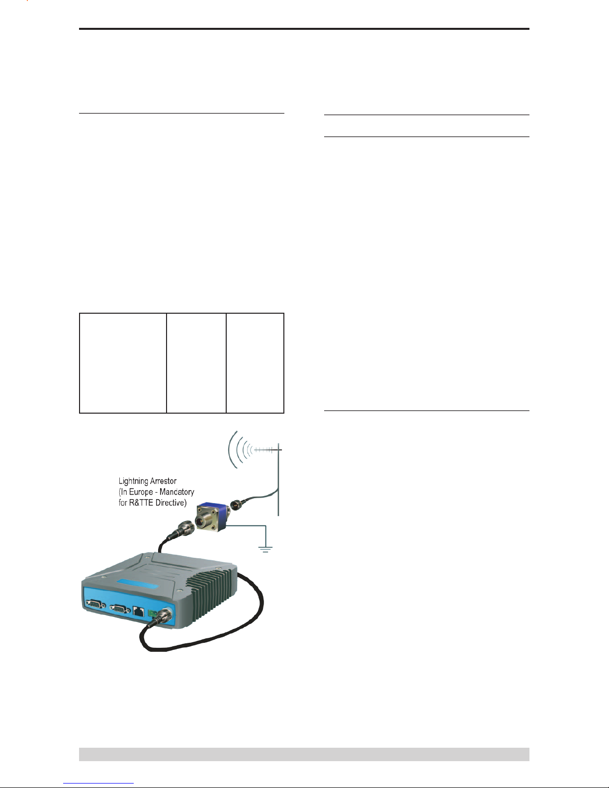
RF Feeders and Protection
The antenna is connected to the radio modem by way of an
RF feeder. In choosing the feeder type, one must compromise
between the loss caused by the feeder, and the cost, exibility, and
bulk of lower loss feeders. To do this, it is often prudent to perform
path analysis rst, in order to determine how much “spare” signal
can be allowed to be lost in the feeder. The feeder is also a critical
part of the lightning protection system.
All elevated antennas may be exposed to induced or direct
lightning strikes, and correct grounding of the feeder and mast are
an essential part of this process. Gas discharge lightning arresters
should also be tted to all sites.
Note: All ETSI installations require the use of a lightning surge
arrestor in order to meet EN6095. See Part A - Preface for lightning
arrestor specications.

Page 19
E Series Data Radio – User Manual
Part D – System Planning and Design
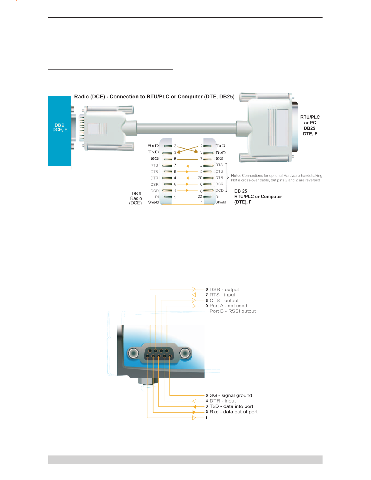
Cable Wiring Diagrams
Page 20
E Series Data Radio – User Manual
Part D – System Planning and Design
RS232 Connector Pin outs (DCE)
Port A and B, Female DB9
Cable Wiring Diagrams
Other manuals for ER450
1
Table of contents
Other Trio Datacom Radio manuals


