Kongsberg SIMRAD Navico RT1200 User manual

Manual
Navico RT1200 / RT1400
VHF Radio

Page 2
The technical data, information and illustrations contained in this publication were to the best of our knowledge correct at the time of going to print. We reserve the
right to change specifications, equipment, installation and maintenance instructions without notice as part of our policy of continuous development and improvement.
No part of this publication may be reproduced, stored in a retrieval system or transmitted in any form, electronic or otherwise without prior permission from Simrad
Navico Ltd.
No liability can be accepted for any inaccuracies or omissions in the publication, although every care has been taken to make it as complete and accurate as possible.
MDL 2/12/98
© 1998 Simrad Navico Ltd
For service and advice please contact the main Simrad dealer in your country of residence.

Page 3
CONTENTS
1. General
1.1 Introduction
1.2 RT1200 and RT1400
1.3 Technical Specification
1.4 Dimensions
1.5 Licensing
2. Operation
2.1 Location of Controls
2.2 Operation - ScanningVersions
2.2.1 Function (F) / Backlight ( )
2.2.2 Power (1/25) / Channel Memory (M+)
2.2.3 Dual Watch (D/W) / Channel Inhibit ( )
+ Revert function
2.2.4 Scan (SCN) / Memory Scan (MS)
2.2.5 Channel 16 (16)
2.2.6 Squelch (Sq)
2.2.7 Volume, On/Off (Vol)
2.2.8 Channel Select (Ch)
2.3 Operation - Non-scanningVersions
2.3.1 Backlight ( )
2.3.2 Working Channel (P)
2.4 Memory Mode (Scanning versions only)
2.5 Second Channel Mode
2.6 Speaker Mute (Handset models only)
3. Installation
3.1 VHF Installation
3.2 Electrical Installation
3.3 Antenna Installation Recommendations
3.4 Electrical Interference Suppression
4. Appendix
4.1 Optional Accessories
4.2 Transmission Range
4.3 Frequency of Channels
4.4 Fault Finding
4.5 Service &Warranty

Page 4
1 General
1.1 Introduction
The RT1200 and RT1400 fixed VHF radio is
designed by Simrad and manufactured at our
modern factory facility in the UK. The radio is
designed to meet or exceed stringent
International Regulations including ETS300-162.
The RT1200 and RT1400 are robustly construct-
ed using a pressure die cast aluminium case for
effective heat dissipation, ensuring maximum
transmission performance even after many
hours constant use.
Please note that VHF regulations vary from
country to country. Simrad sets are approved
specifically by the countries in which they are
sold and consequently there may be differences
in the programming of sets bought in different
countries. If using outside the country of pur-
chase, it is vital to check that the set conforms
to local regulations before use.
Thank you for choosing Simrad
If you are pleased with your VHF we hope you
will be interested in our range of marine elec-
tronic equipment, which is manufactured to
the same high standards as the RT1200/1400.
Please contact your nearest Simrad Agent for a
catalogue showing our increasing range of
high tech navigational instruments, GPS,
autopilots, Radar, Fishfinders and VHF radio
sets.
Simrad operate a policy of continual develop-
ment and reserve the right to alter and
improve the specification of their products
without notice.
F
16
1/25
D/W
SCN
Sq
Vol
M+
MS
RT1200 & RT1400Waterproof FixedVHF
OR

Page 5
1.2 RT1200 and RT1400
The Simrad fixed VHF range consists of two models - the RT1200 and RT1400. Both are available
with either a fistmike or telephone handset, and offer the same features including channel scan,
channel memory, dual watch etc. The details in this owner’s manual apply to both models.
The RT1400 model features an additional watchkeeping receiver, allowing it to use the Digital
Selective Calling (DSC) system for routine and distress calling on VHF channel 70. For this the
RT1400 will need to be linked to the Simrad DSC control unit DSC1400 (DSC Class D). DSC com-
patibility is not available with the RT1200 model.
This manual describes all operating features available to the RT1200 and RT1400 models, includ-
ing channel scan, which is not permitted in certain countries. Therefore this feature may not be
available on the set supplied if it was purchased or configured for one of these countries.
1.3 Technical Specification
Power Supply 12v DC (10.8v - 15.5v DC)
Channel Capability 55 international channels 1-28, 60-88 simplex & semi-duplex
UK : includes M (previously 37) and M2
USA : includes 0, 29, 89, 75, 76, Wx1-10 receive only.
Scandinavia : leisure or fishing channels as appropriate.
Canada : Canadian and USA channels.
Private Channels Up to 16 private channels*
External Speaker Impedance 8Ω
Transmit -
Frequency Range 155-163Mhz
Power Output 1 watt or 25 watts
Current Consumption 5.5A (25 watts)
1.3A (1 watt)
Harmonic and Spurious Emissions < 0.25µW
Hum / Noise < -40dB
Modulation ±5kHz
Receive
Audio Output Power 6 watts
Current Consumption 300mA (Full Volume, illumination on)
180mA (Fully Squelched, illumination off)
Sensitivity < 0.5µV emf for 20 dB SINAD
Harmonic and Spurious Emissions < -2nW
Hum / Noise < -40dB
Adjacent Channel Selectivity 70dB
Intermodulation Rejection 70dB
* Contact local Simrad Technical Dealer for further details of channel programming etc.
Environmental
VHF Radio Waterproof to IP66 (IP67 when flush mounted)
Fistmike / Telephone Handset Waterproof to IP67

Page 6
F
16
1/25
D/W
SCN
Sq
Vol
M+
MS
1.4 Dimensions
185mm (7.4in)
158mm (6.2in)
66mm (2.6in)
22mm (0.9in)
47mm (1.8in) 55mm (2.2in)
79mm (3.1in)
213mm (8.4in)
54mm (2.2in) 70mm (2.8in)

Page 7
1.5 Licensing
Prior to use check the national licensing requirements for the operator.
In the UK license applications and queries should be made to the following authority -
Wray Castle
Ship Radio Licensing
PO Box 5
Ambleside
LA22 0BF
Tel - 01539 434662
A set may only be operated by, or under the supervision of a holder of a Certificate of
Competence and Authority to Operate. This involves a simple examination and an annual
license renewal fee. The VHF only certificate is administered by the Royal Yachting Association -
Royal Yachting Association
RYA House
Romsey Road
Eastleigh
Hants, SO5 4YA
Tel - 01703 629962
Holders of the Restricted Certificate of Competence in Radio-telephony (which covers MF/HF
SSB etc), do not need a separate VHF certificate.
In the USA license applications should be made to -
Federal Communications Commission
Gettysburg
PA17325
Washington DC 20554
In Canada, license applications should be made to -
Department of Communications
300 Slater Street
Ottawa
Ontario, K1A 0C8
In all other countries, please contact your regional authority for information.

Page 8
Fig 2.1 - Control functions
2 Operation
2.1 Location of Controls
The RT1200 and 1400 VHFs are very simple to operate, using only five buttons and three rotary
knobs to access a variety of functions. The functions available will depend on whether the radio is
a scanning or non-scanning version (scanning functions are not permitted in certain countries).
Control Legend Primary function Secondary function
1 F/ Used to access secondary functions* Switch backlighting on/off
2 1/25 Select transmit power (1w / 25w) Enter selected channel into memory*
3 D/W Dual Watch Inhibit channel from scan*
4 SCN/P Scan all channels* / Select working channel† Scan channels in memory sequentially*
5 16 Select channel 16
6 Sq Squelch adjust
7 Vol On–off / Volume adjust
8 Ch Channel select knob
F
16
1/25
D/W
SCN
Sq
Ch
Vol
M+
MS
16
1/25
D/W
P
Sq
Ch
Vol
12 6 7
345 8
* Scanning versions only † Non-scanning versions only
12 6 7
345 8
Scanning
version
Non-scanning
version

Page 9
2.2 Operation - ScanningVersions
The radio is switched on by turning the volume
knob clockwise. The VHF starts up automati-
cally on channel 16* at maximum power (25w).
2.2.1 Function (F) / Backlight ( )
NOTE - Secondary functions are only available
on scanning versions of the VHF.
Several of the keys have secondary functions in
addition to the main function. These are
accessed by pressing F, then the appropriate
key within two seconds (do not hold the Fkey
down). When Fis pressed, the F legend will
appear on the LCD for the two seconds it is
active. Pressing another key within this time
will access its second function.
Backlighting - The LCD backlighting is
switched on and off as a secondary function of
the Fkey. To turn the backlighting on/off press
Ftwice (Fig 2.2). If the Fkey is kept held down
the second time when switching the backlight-
ing on, the lighting will step through five
brightness levels. Release the key when the
desired lighting level is reached.
2.2.2 Power (1/25) / Channel Memory (M+)
Although the radio has a maximum transmit
power of 25 watts*, this is not always necessary
if communicating with a station or vessel that
is very close. To reduce power consumption,
the transmit power can be reduced to 1 watt.
This key operates as a toggle, switching
between 1w and 25w (Fig 2.3).
NOTE - Some channels are restricted to 1w
transmit power. The radio is programmed to
switch to low power automatically when one
of these channels is selected
Channel Memory function - This will add the
currently selected channel into the Scan
Memory. Press F then 1/25 - the LCD display
will show ENT indicating that the channel has
been entered into the Scan Memory. Pressing F
then 1/25 if the channel is already in the memo-
ry will remove it - indicated by DEL appearing
on the bottom line of the LCD display.
* Programmable - please enquire with authorised Simrad Technical Dealer
F
16
1/25
D/W
SCN
M+
MS
F
PRESSED TWICE
F
16
1/25
D/W
SCN
M+
MS
Fig 2.2 - Switching backlighting on
F
16
1/25
D/W
SCN
M+
MS
1/25
F
16
1/25
D/W
SCN
M+
MS
Fig 2.3 - Selecting transmission power (1/25W)
1W
25W

Page 10
2.2.3 Dual Watch (D/W) / Channel
Inhibit ( ) + Revert function
Dual Watch enables the radio to scan between the
selected channel and the priority channel (nor-
mally CH16). To activate Dual Watch Mode,
select the channel and press D/W - the D/W leg-
end will be displayed on the LCD.
Note that the radio will not transmit, nor will
alternative channels be able to be selected while
in Dual Watch mode. To restore normal opera-
tion, either press SCN, 16 or rotate the channel
select knob anticlockwise.
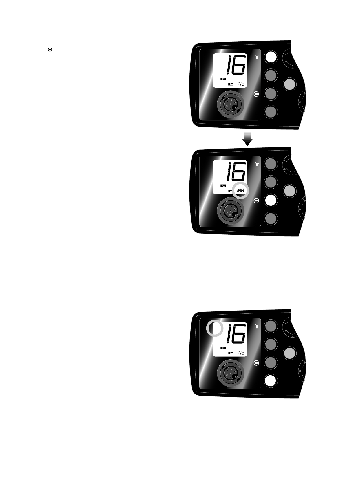
Inhibit Function - Since the Scan function stops on
channels where a signal is detected, the radio will
lock onto a channel with a lot of interference noise,
or if it is transmitting a continuous carrier wave
signal, preventing the radio from continuing the
scan. The Inhibit function allows channels to be
removed from the Scan while remaining available
for use on the radio. Pressing F then D/W will
inhibit the current channel - indicated by INH
appearing on the bottom line of the display (Fig
2.4). Pressing F then D/W if the channel is already
in inhibited will restore it to the Scan - indicated by
SCN appearing on the bottom line of the display.
REVERT Function - If D/W is pressed when
CH16 is selected, the VHF will revert to the pre-
viously selected channel.
2.2.4 Scan (SCN) / Memory Scan (MS)
This function scans through each channel
sequentially until a signal is detected above the
squelch level set. Once the signal ends or drops
below the squelch level, the radio will continue
scanning. Press SCN to enter scan mode. The
LCD will show SCAN (Fig 2.5).
Note that the radio will not transmit, nor will
alternative channels be able to be selected while
in Scan mode. To restore normal operation,
either press SCN, 16 or rotate the channel select
knob anticlockwise. Rotating the channel selec-
tor clockwise while in Scan Mode will step the
scan on to the next channel.
The Memory Scan function (F then SCN) oper-
ates in the same way as the Scan function, except
that it will only scan channels that have been
entered into the Scan Memory. If no channels
have been entered into the memory then this
function will not be available.
F
16
1/25
D/W
SCN
M+
MS
F
F
16
1/25
D/W
SCN
M+
MS
D/W
Fig 2.4 - Inhibiting channel from Scan
F
16
1/25
D/W
SCN
M+
MS
Fig 2.5 - Entering Scan mode
SCN
SCA

Page 11
2.2.5 Channel 16 (16)
Will automatically select Channel 16 on High
Power when pressed. Any function active (Dual
Watch, Scanning etc) will be cancelled.
2.2.6 Squelch (Sq)
This knob is used to adjust the receiver muting
threshold (squelch) level. To cut out weaker sig-
nals, increase the squelch until the background
interference noise disappears. To receive weaker
signals, decrease the squelch.
2.2.7 Volume, On/Off (Vol)
The radio is switched on by turning the volume
knob clockwise. To increase the volume, turn the
knob further clockwise. To reduce the volume,
turn the knob anticlockwise. Turn the knob fully
anticlockwise to switch off.
2.2.8 Channel Select (Ch)
The VHF features a rotary channel selector.
Rotate the knob clockwise to scroll up through
the available channels, anticlockwise to scroll
down (Fig 2.6).
2.3 Operation - Non-scanningVersions
In countries where scanning radios are not per-
mitted, the secondary functions listed are not
available (Fig 2.7). The primary functions are the
same with the following exceptions -
2.3.1 Backlight ( )
On non-scanning versions of the radio the Fkey
is replaced with a backlighting key . Turning
the backlighting on and off requires only a single
press of the key. Press and hold the key when
switching the backlight on to step through the
five lighting levels and release when the desired
lighting level is reached.
2.3.2 Working Channel (P)
This function allows a user selectable working
channel to be programmed. Select the channel,
then press and hold P. Initially the display will
show the previously selected channel, but after 2
seconds the display will show the new channel
and USE will appear on the bottom line of the
display. This channel can now be directly
accessed by pressing P.
F
16
1/25
D/W
SCN
Sq
Ch
M+
MS
F
16
1/25
D/W
SCN
Sq
Ch
M+
MS
Fig 2.6 - Changing channels
16
1/25
D/W
P
Fig 2.7 - Controls – non-scanning versions

Page 12
2.4 Memory Mode
This function is only available on scanning ver-
sions of the VHF. It allows the radio to operate
using only the channels programmed into the
channel memory (see section 2.2.2).
Press Fthen SCN, keeping SCN held down for
2 seconds. Rotating the channel select knob
will then only select the channels programmed
into the memory. To disable this mode and
return to normal operation, either switch the
radio off and on again, or press 16.
This mode will only be available if there are
channels programmed into the memory.
2.5 Second Channel Mode
In countries where it is permitted, holding
F/ down while turning the radio on will
enable the radio to operate on a secondary set
of channels - normally the USA channels (Fig
2.8). Where the LCD will normally show INT
on the bottom line (indicating that it is using
the standard International channel set), the dis-
play will show USA for USA channels, CAN
for Canadian channels etc. Channel sets avail-
able will vary depending on which country the
radio is programmed for use in. Please enquire
with your national licensing authority for
details of permitted channel sets.
The radio will revert to normal operation if it is
switched off then on again.
2.6 Speaker Mute
On models fitted with a telephone handset, lift-
ing the handset from the cradle will normally
mute the loudspeaker automatically.
If required, this function can be disabled by
holding down D/W while turning the radio on.
The loudspeaker will subsequently remain on
when the handset is lifted.
As this setting is stored in the radio’s non-
volatile memory it will be remembered even if
the radio is totally disconnected from the
power. To restore speaker muting, hold down
D/W again while turning the power on.
F
16
1/25
D/W
SCN
M+
MS
F
16
1/25
D/W
SCN
M+
MS
POWER ON
F
Fig 2.8 - Selecting secondary channel set

Page 13
3 Installation
3.1 VHF Installation
The radio should be sited so that engine noise
and vibration or other background noise do not
make it difficult for the operator to hear.
Although the RT1200/RT1400 radio is water-
proof when flush mounted, it is recommended
that it is not installed where it will be exposed
to continuous direct sunlight, as this will even-
tually damage the LCD display.
As microphones and loudspeakers contain
powerful magnets, the radio should not be
installed within 1m (3ft 3in) of any compasses,
whether magnetic or electronic.
The fins on the back of the case act as a heatsink
to dissipate heat generated by the set when in
use, which maintains the high
efficiency of the radio. The free circulation of
air is essential - if mounting the radio in an
enclosed space, ensure that the space is vented.
The VHF is supplied with a reversible mount-
ing bracket. This can be used to mount the
VHF on the chart table or on an overhead bulk-
head (Fig 3.1). The bracket is fixed in place
using four No.10x3⁄4screws (supplied). Before
installing, ensure that there is at least 88mm
(3.5 in) vertical clearance and 70mm (2.8in)
horizontal clearance behind the bracket to
allow the radio to fit (Fig 3.2).
The radio is fixed to the bracket using a simple
clamp arrangement. The peg on the left side of
the radio is slotted into the hole in the bracket.
The clamp on the right side of the radio can
then be slid into the slotted aperture on the
bracket and tightened to hold the radio firmly
in place (Fig 3.3). The rake angle of the radio
can be adjusted by slackening the clamp.
An alternative mounting method is to use the
flush mounting kit FMB1000BK (supplied sep-
arately). This allows the radio to be neatly
installed inside a bulkhead, so that only the
fascia of the radio is visible. For more details of
this and other accessories available, please
refer to section 4.1.
F
16
1/25
D/W
SCN
Fig 3.1 - Standard mounting options
1. Fit locating peg (left side) into hole in bracket
2. Slide locking clamp (right) into slot in bracket
3. Tighten clamp
Fig 3.3 - FixingVHF to bracket
1
2
3
Desktop mounting Overhead mounting
Fig 3.2 - Minimum clearance required
100mm (3.9in)
88mm (3.5in)

Page 14
3.2 Electrical Installation
The RT1200/1400 has four electrical connections - the handset/fistmike socket is on the front
panel below the LCD display (Fig 3.4A). The other three are situated on the back of the case - the
antenna socket is on the left (Fig 3.4B). DC power is supplied to the set via a two core flying lead
(Fig 3.4C), below which is a 3.5mm jack socket for an optional extension speaker (Fig 3.4D). This
socket is covered by a weather plug when not in use.
The VHF requires a 12v DC supply to operate, and is supplied with a power lead which incorpo-
rates an in-line 7.5 amp fuse. This lead should be connected to the vessel’s power supply, keep-
ing the cable runs as short as possible. Although the radio draws very little current when receiv-
ing, a heavier current is drawn when transmitting which may result in a voltage drop if very long
cable runs are used of inadequate core diameter. If the supplied power lead is not long enough,
an extension of up to 3m (10 ft) can be made using at least 2.5mm2(13AWG) wire.
The red wire is positive and black is negative. If polarity is accidentally reversed, the set is protected
but the fuse will blow. Ensure that it is replaced with a fuse of the correct 7.5 amp rating. The radio
is designed to be easily removable for storage or security, so leave an adequate length of cable to
ease disconnection. The flying lead from the rear of the radio can then be plugged into the power
supply lead. Note that the configuration of the plug prevents incorrect connection.
The antenna is connected to the radio using a standard PL259 type connector as fitted to most
marine antennae. If fitting to an existing antenna, check that the contacts are not corroded before
connecting, as this will affect the quality of the signal. Ensure that the retaining collar of the
antenna plug is securely tightened to prevent accidental disconnection.
The extension speaker socket takes a standard 3.5mm jack plug. The speaker used must have a
minimum impedance of 8Ω.
F
16
1/25
D/W
SCN
Sq
Vol
M+
MS
A- Handset/
Fistmike
B- Antenna
C- 12v DC
D-
Extension
Speaker
Fig 3.4 - External connections

Page 15
3.3 Antenna Installation Recommendations
The most important factor in the performance of
the radio will be the quality and positioning of
the antenna. Most recorded problems with
VHF radios are related to poor antenna siting,
faulty cabling, poor quality cable joints and low
voltage supply. Even a VHF as highly advanced
as the RT1200/RT1400 cannot compensate for
these factors. Therefore, if replacing an existing
VHF installation, it is important that these fac-
tors are checked when installing the radio.
As the range of VHF signals are governed by
line of sight (see section 4.2), the antenna
should be placed as high as possible, while
remaining clear of any metallic objects that
could influence the resonance of the antenna.
The most popular antennae for marine use are
1m (3ft 3in) long. On sail boats these are usu-
ally mounted on the masthead, where the
length of the antenna keeps it clear from the
navigation lights and windvanes etc. This type
of antenna can also be mounted on the cockpit
roof or garage of power boats.
Longer whip antennae are recommended for
larger boats. These radiate the same total
power as smaller antennae, but concentrate it
into a narrower beam, which is advantageous
on a tall mast at extreme range where concen-
trating the available power into a narrow hori-
zontal beam becomes more important.
However, if the antenna is not vertical when
transmitting, the beam will be angled either too
high or too low (Fig 3.6). Here the wider beam
of the shorter antenna will be more universally
effective, although the signal will be weaker
(Fig 3.5). Therefore vessels with a large heel
angle (small sailboats) would be better choos-
ing a short masthead antenna. Your local agent
should be able to provide specific advice on
antenna choice for the vessel it is to be fitted to.
The antenna coaxial cable and any connectors
used must be rated at 50Ω. Under no circum-
stances should standard domestic TV cable and
connectors be used. Incorrectly rated cabling
and connectors could result in power not
reaching the antenna, but also power could be
reflected back into the radio, damaging it in the
process.
Fig 3.5 - Effect of heel on range of 1m marine
antenna
Fig 3.6 - Effect of heel on range of longer whip
antenna

Page 16
The quality of any connections and integrity of the cable (i.e no breaks in the sheathing) will
directly affect the performance of the radio. Poor soldering or corrosion of the terminals can
impair performance. It is recommended that screw or crimp terminal type connectors are not
used for any through deck fittings - a good quality waterproof solder terminal connector will be
less susceptible to poor connection due to corrosion of the contacts.
3.4 Electrical Interference Suppression
Interference generated by the alternator of the engine may occasionally cause problems. The
radio has been designed to minimise the effects of outside interference. However, precautions
should still be taken - route the power supply and antenna cables away from the engine com-
partment. The cable run should not be down the same trunking as other cables carrying high cur-
rent. The antenna cable should also be kept seperate from the radio’s power cable.
Engines with spark ignition - and also some refrigerators - should be fitted with suppressors.
Your local agent should be able to give advice on this, and also supply suppression kits where
necessary.

Page 17
4 Appendix
4.1 Optional Accessories
The following accessories are available from
your nearest Simrad Technical Dealer. Please
quote the correct part number when ordering.
FMB1000BK Flush Mount Kit
Sutiable for RT1200, RT1400 and DSC1400
1
4
7
C
2
5
8
0
3
6
9
ALL SHIPS URGENCY
FROM : 123456789
RESP : SIMPLEX CH 16
REC’D : 18 07 97 16:42
ENTER
D
I
S
T
R
E
S
S
B
U
T
T
O
N
O
P
E
N
C
O
V
E
R
DSC1400 DSC Controller (Class D) for use with
RT1400
THS-4BK Spare telephone handset FTM-4BK Spare fistmike

Page 18
4.2 Transmission Range
Because VHF signals travel in a straight line
and are not reflected back off the ionosphere as
lower frequency signals are, the range of VHF
signals is limited to ‘line of sight’, beyond
which the other vessel passes behind the curve
of the Earth. Therefore, the range will increase
greatly the higher above sea level the antenna
is, as Fig 5.1 illustrates (assuming maximum
transmission power is used):
,,,
30 m/
100 ft
Mast
9 m/
30 ft
Mast
87 km / 65 M
13-16 km
8-10 M
20 km / 12 M
8 km / 5 M
20-26 km / 12-16 M
46-53 km / 29-33 M
Cherbourg Isle of Wight
Endeavour
Niton
Fig 4.1 -VHF transmission range
Therefore, the typical ship to ship range of a
fixed VHF radio such as the RT1200/RT1400
with a masthead antenna will be approximate-
ly 20 Km (12 miles). This will increase as
height above sea level increases, or if the other
radio user’s antenna is at a greater height - note
that the range between the yacht with the
antenna mounted on a 9 M (30 Ft) mast and the
shore station increases to 46-53 Km (29-33
Miles).

Page 19
4.3 Frequency of Channels
Channel 0 will only be made available in the
UK to Coastguard users with written authorisa-
tion.
Channels M and M2 are UK marina channels
and will not be programmed on non-UK radios.
Channel 70 is the designated Digital Selected
Calling (DSC) channel and can only be used by
an RT1400 + DSC1400.

Page 20
4.4 Fault Finding
Symptom Possible Cause Remedy
Unit will not switch on * Faulty connection to power * Check power connection
* Fuse has blown * Replace fuse and check
power supply current
Scan or Memory Scan is * Noise on the channel is * Increase squelch level
locking on a channel holding the scan * Inhibit channel from scan
without a signal (see section 2.2.3)
Dual Watch not being * Priority channel selected * Select a working channel
entered * Handset off cradle * Replace handset
Cannot change channel * Dual Watch (D/W) engaged * Exit Dual Watch
Certain channel numbers * Some channels are restricted * Consult your national
are not obtainable and not programmed depend- authority for permitted
ing on country of purchase channels in your region
Will not transmit * Scanning or D/W function active * Exit D/W or Scan
Will not transmit on 25W * Low voltage when full transmit- * Check power supply
but OK on 1W ting current is drawn
* Some channels are restricted to * Consult your national
low power transmission only authority
Transmissions persistently * Damaged antenna * Replace antenna
weak / display flashes ‘ANT’ * Antenna cable broken * Replace cable
* Poor contact * Check antenna sockets &
through deck connector
These simple checks should be carried out before seeking technical assistance and may save time
and expense. Before contacting your servicing agent please obtain the radio’s serial number. The
software iteration should also be quoted - this is shown in the large digits on the display for 2
seconds after the radio is turned on and should be written in the box below for future reference.
RADIO SERIAL No. SOFTWARE ITERATION
This manual suits for next models
1
Table of contents
Other Kongsberg Radio manuals