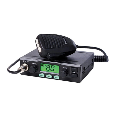
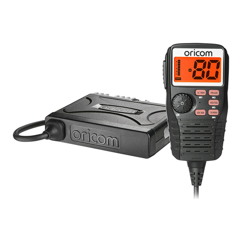
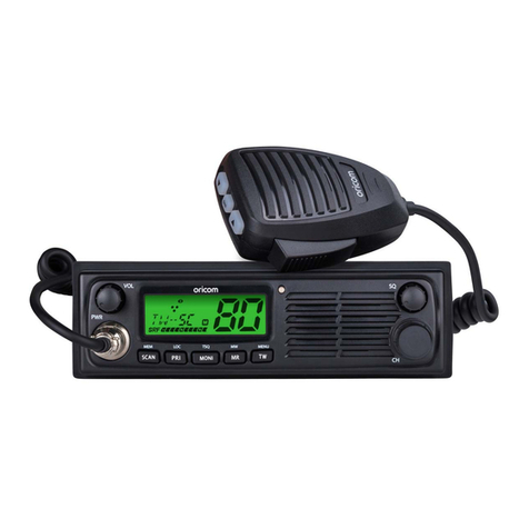
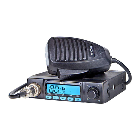
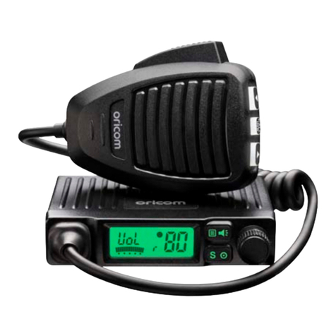
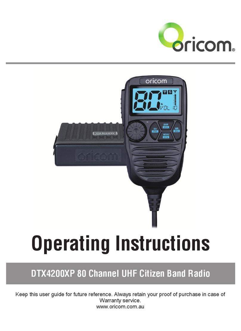
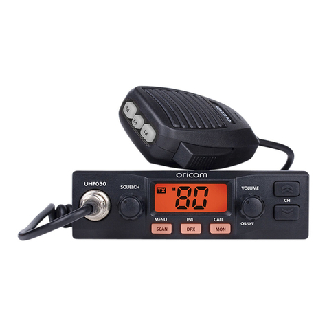
Oricom UHF360 User manual

1
UHF360 Quick Set Up Guide
For the full product User guide, please scan QR code
or visit www.oricom.com.au
Pack contents
•UHFCBRadioTransceiver
•HeavyDutyControllerSpeaker
Microphone
•Microphonemountingbracket
•Transceivermountingbracket
•Packofsuppliedmountingscrews
•QuickStartGuide
Please read before installing or operating your Oricom radio
TheoperationofyourUHFradioinAustraliaandNewZealandissubjectto
conditionsinthefollowinglicenses:InAustralia,theACMARadiocommunications
(CitizenBandRadioStations)andinNewZealandbyMEDtheGeneralUserRadio
LicenseforCitizenBandRadio.
Need help? Contact Oricom Support
IfyouneedassistancesettinguporusingyourOricomproductnoworinthefuture,
callOricomSupport.
Australia (02)45748888
www.oricom.com.au
Mon-Fri8am–6pmAEST
NewZealand 0800674266
Mon-Fri10am–8pmNZST
Whenanewnarrowbandradioreceivesatransmissionfromanolderwidebandradiothespeechmaysoundloud
anddistorted–simplyadjustyourradiovolumeforthebestlisteningperformance.Whenanolderwideband
radioreceivesasignalfromanewnarrowbandradiothespeechmaysoundquieter-simplyadjustyourradio
volumeforbestlisteningperformance.WhenoperatinganarrowbandradioorChannel41-80interferenceis
possiblefromwidebandradiostransmittingonhighpoweroronadjacentfrequency.
Theissuesdescribedabovearenotafaultoftheradiobutaconsequenceofmixeduseofwidebandand
narrowbandradios.
ThisunitcomplieswithallrelevantAustralianandNewZealandapprovalrequirementsAS/NZS4365:2011

2
Controls and Indicators
Front View of Controller Speaker Microphone
PushtoTalk(PTT)
LCDdisplay
On/Off,Mode
(volume/channel/SQ)
Monitor/Tonesquelch
Speaker Microphone
Down
Triplewatch/Menu
Up
Scan/Memoryskip
Rear View of Radio
AntennaJack
Powersupplyconnection
3.5mmexternaljackforoptional8ohmspeaker
LCD Icons & Indicators
Signalstrength
&TXmeter
Triple
watch on Duplexon
Status
display Channeldisplay
Memory
channel
Roger
Beepon
CTCSSon
DCS
on
Scrambler
on
CTCSSorDCS
channeldisplay
Warnings and Safety Information
WARNING
Potentially Explosive Atmosphere
TurnyourradioOFFwheninanyareawithapotentiallyexplosiveatmosphere.Sparksinsuchareas
couldcauseanexplosionorreresultingininjuryorevendeath.
NOTE:Areaswithpotentiallyexplosiveatmospheresareoften,butnotalwaysclearlymarked.They
includefuellingareassuchasbelowdeckonboats;fuelorchemicaltransferorstoragefacilities;
areaswheretheaircontainschemicalsorparticles,suchasgrain,dust,ormetalpowders;andany
otherareawhereyouwouldnormallybeadvisedtoturnoffyourvehicleengine.
Blasting Caps and Areas
Toavoidpossibleinterferencewithblastingoperations,turnyourradioOFFnearelectricalblastingcaps
orina“blastingarea”orinareasposted:“Turnofftwowayradios.”Obeyallsignsandinstructions.
Electromagnetic Interference/Compatibility
Nearlyevery electronicdevice issusceptible toelectromagneticinterference (EMI).To avoidthe
possibilityofelectromagneticinterferenceand/orcompatibilityconicts,turnoffyourradioinany
locationwherepostednoticesinstructyoutodososuchashealthcarefacilities.
CAUTION
Thisradioisdesignedforoperationona12Voltbatterysystem.Itshouldnotbeconnecteddirectly
toa24Voltsystem.
Wheninstallingyourradioinyourvehicle,checkthatduringinstallationyoudonotdamageany
wiringorvehiclecomponentsthatmaybehiddenaroundthemountingposition.
Ensuretheinstallationdoesnotinterferewiththeoperationofthevehicleandmeetsallregulatory
andsafetyretirementsforaccessoriesttedtoyourvehicle.
Foroptimumperformance,yourradioneedstobeinstalledcorrectly.Ifyouareunsureabouthow
toinstallyourradio,wesuggestyouhaveyourradioprofessionallyinstalledbyaUHFspecialistor
Autoelectrician.Wheninstallingtheradio,avoidmountingitclosetoheatersorairconditioners.
NeverpressthePTTbuttonbeforeconnectingtheantennatotheradio.

3
Installation of Your Oricom Radio
Fitting the Controller Speaker Microphone
Thecontrollerspeakermicrophoneusesa6-pintelephonestyleplugandsocket:
1.Positionthemicrophoneplugsotheplasticapfacesupward,andinserttheplugintothesocketuntilit
‘clicks’.
2.Gentlypresstherubberbootintotheholesurroundingthesocketsothattheslotaroundthebootts
neatlyinsidetherimoftheentryhole.
Disconnecting the Controller Speaker Microphone
ItisrecommendedthattheControllerSpeakerMicrophonebeleftpermanentlyconnectedtotheradio,butif
itmustbedisconnected,proceedasfollows:
1.Lifttherubberbootandthelipoftheraisedareaonthefrontpanel.
2.Easetherubberbootoutofthecableentryholeandslideitalongthecableawayfromthefrontpanel.
3.Identifythepluglockinglever,andmovethelevertowardstheplugbody.Atthesametimegentlypullthe
plugfromthesocket.
Wiring Methods
Therearetwopossiblewiringcongurationsforconnectingtothevehiclespowersupply.
A. Radio stays ON when the ignition is switched OFF
Connecttheradio’snegative(black)leadtothevehiclechassis,ordirectlytothebattery’snegativeterminal.
Connecttheradio’spositive(red)leadviathe3Ampfusetothebattery’spositiveterminal.Alternatively,
thepositiveleadcouldbeconnectedatthefuseboxatapointthathasDCPowercontinuouslyavailable
(preferablythebatterysideoftheignitionswitch)viathe3Ampfuse.
B. Radio turns OFF with the ignition switch
Connecttheradio’snegative(black)leadtothevehicle’schassis,ordirectlytothebattery’snegative
terminal.
Theradiospositive(red)leadshouldconnecttoanaccessorypointinthevehicle’sfuseboxviathe3Amp
fuse.
Antenna information
Theantenna(notsupplied)isofcriticalimportancetomaximiseyouroutputpowerandreceiversensitivity.
Apoorlyinstalled,inferiorqualityantenna,oronenotdesignedforthecorrectfrequencyband,willgive
poorperformance.Youshouldonlypurchaseanantennadesignedforthe477MHzfrequencyband.
Antenna installation
Toobtainmaximumperformancefromtheradio,selectahighqualityantennaandmountitinagood
location.
Never press the PTT before connecting an antenna to the radio.
Optional accessories
SPE85 Externalspeaker
Ifrequired,youmayinstallanexternal(8ohm,Minimum5Wpower)speaker
ttedwitha3.5mmplug(notsupplied).
Dependingontheinstallation,itmaybenecessarytouseanexternalspeaker
(notsupplied)togiveimprovedvolumeandclarity.Thiscanbepluggedintothe
externalspeaker(SP)socketontherearoftheunit.
MMM100 Magnetic microphone holder

4
Quick Overview of Basic Controls
Turning on the Power
PressandholdthePower/Modebutton.
Atpoweron,thecurrentappliedDCvoltageisdisplayednumericallyasshownbelow.
Specialoverandundervoltagedetectioncircuitryprotectstheradioandwarnsofexcessivevoltage
conditionsbytheLCDashingthe3backlightcolours.
MODE
Setting the Volume
Pushtheupordownbuttonstoadjustthesoundlevelforcomfortablereception.
Selecting a channel
PressPower/Modebuttononce.“CH”willappearontheLCD.SelectthechannelbyUporDownbutton.
MODE
Setting the Squelch Level
1.PressPower/Modebutton2times.Thecurrentsquelchlevelisdisplayed.
2.SelectthesquelchlevelbyUporDownbuttons.
Theradiohas16preset(offto15)squelchlevels,off-Squelchopen.
1-Max.sensitivity(Min.squelch)
15-Min.sensitivity(Max/Tightsquelch)
MODE
Note:*Ifabuttonisnotpressedwithin5seconds,theradiowillautomaticallyexitthesubdisplayof“VOL”
“CH”and“SQL”.
PTT (Push-To-Talk) button
Beforetransmitting,alwayslistenonthechanneltomakesureitisnotbeingusedbyanotheroperator.
PressingthePTTallowsaudiotobetransmitted,byspeakingacrossthefrontofthecontrollerspeaker
microphone.
TXisindicatedbythelevelbarsontheLCDdisplay.Toreceive,releasethePTTbuttonandthenTXwill
disappearonthedisplay.
Whentransmitting,holdtheMIC5cmfromyourmouthandspeakclearlyinnormalvoiceacrossthefront
of the mic.
Factory Reset
Iftheradio’sdisplaylocksuporstopsfunctioningproperly,youmightneedtoresetyourUHFradio.
Caution:ThisprocedureclearsalltheinformationyouhavestoredinyourUHFradio.
BeforeyouresetyourUHFradio,tryturningitoffandonagain.
IfyourUHFradioisstillnotfunctioningcorrectly,youmayneedtoresettheUHFradio.
Toreset,pressandholdmonitorbuttonandpoweron.“Reset”willappearinthedisplay.Theradiowillthen
returntostandbymode.

5
UHF CB channels and frequencies
EMC Technologies (NZ) Ltd
Test Report No 101127.1
Report date: 25th November 2010
6.2 Nominal Carrier
Table 1 Nominal Carrier Frequency
Channel
Tx Rx
Channel
Tx Rx
Freq Freq Freq Freq
MHZ MHz MHz MHz
01* 476.4250 476.4250 21 476.9250 476.9250
41* -476.4375 61‡ — —
02* 476.4500 476.4500 22† 476.9500 476.9500
42* -476.4625 62‡ — —
03* 476.4750 476.4750 23† 476.9750 476.9750
43* -476.4875 63‡ — —
04* 476.5000 476.5000 24 477.0000 477.0000
44* -476.5125 64 477.0125 477.0125
05* 476.5250 476.5250 25 477.0250 477.0250
45* -476.5375 65 477.0375 477.0375
06* 476.5500 476.5500 26 477.0500 477.0500
46* -476.5625 66 477.0625 477.0625
07* 476.5750 476.5750 27 477.0750 477.0750
47* -476.5875 67 477.0875 477.0875
08* 476.6000 476.6000 28 477.1000 477.1000
48* - 476.6125 68 477.1125 477.1125
9 476.6250 476.6250 29 477.1250 477.1250
49 476.6375 476.6375 69 477.1375 477.1375
10 476.6500 476.6500 30 477.1500 477.1500
50 476.6625 476.6625 70 477.1625 477.1625
11 476.6750 476.6750 31* 477.1750 477.1750
51 476.6875 476.6875 71* 477.1875 -
12 476.7000 476.7000 32* 477.2000 477.2000
52 476.7125 476.7125 72* 477.2125 -
13 476.7250 476.7250 33* 477.2250 477.2250
53 476.7375 476.7375 73* 477.2375 -
14 476.7500 476.7500 34* 477.2500 477.2500
54 476.7625 476.7625 74* 477.2625 -
15 476.7750 476.7750 35* 477.2750 477.2750
55 476.7875 476.7875 75* 477.2875 -
16 476.8000 476.8000 36* 477.3000 477.3000
56 476.8125 476.8125 76* 477.3125 -
17 476.8250 476.8250 37* 477.3250 477.3250
57 476.8375 476.8375 77* 477.3375 -
18 476.8500 476.8500 38* 477.3500 477.3500
58 476.8625 476.8625 78* 477.3625 -
19 476.8750 476.8750 39 477.3750 477.3750
59 476.8875 476.8875 79 477.3875 477.3875
20 476.9000 476.9000 40 477.4000 477.4000
60 476.9125 476.9125 80 477.4125 477.4125
* The primary use for these channels is repeater operation using 750 kHz offset. Channels 1-8
inclusive are used for mobile reception and channels 31-38 for mobile transmission. They may also
_____________________________________________________________________________________________________________________________________________________
EMC Technologies (NZ) Ltd
STREET ADDRESS - 47 MacKelvie Street, Grey Lynn, Auckland, NZ Phone: +64 9 360 0862 Fax: +64 9 360 0861
POSTAL ADDRESS - PO Box 68 307, Newton, Auckland, New Zealand E-mail: aucklab@ihug.co.nz
Page 11 of 23 This report may not be reproduced except in full
* Theprimaryuseforthesechannelsisrepeateroperationusing750kHzoffset.Channels1-8inclusive
areusedformobilereceptionandchannels
31-38formobiletransmission.Notethatadditionalchannels41-48and
71-78arealsoavailableforrepeateroperationtosupplementchannels1-8and-31-38respectively
asapprovedbytheACMACBRSClassLicenceinAustraliaandtheMEDGURLinNewZealand.In
addition,anydesignatedrepeaterchannelmaybeusedforsimplexoperationinareaswhereitisnot
used for repeater operation.
† Speechtelephonyshallbeinhibitedonthesechannels.
‡ AtthetimeofproductionChannels61,62and63areguardchannelsandarenotavailableforuse.
Channel5and35(pairedforDuplexrepeaters)arereservedasemergencychannelsandshouldbeused
onlyinanemergency.
CTCSSandDCSwillnotoperateonthesechannels.
AlistofcurrentlyauthorisedchannelscanbeobtainedfromtheACMAwebsiteinAustraliaandtheMED
websiteinNewZealand.Channel11isacallingchannelgenerallyusedtocallothersandchannel40isthe
customaryroadvehiclechannel.
Oncecontactisestablishedonthecallingchannel,bothstationsshouldmovetoanotherunused"SIMPLEX"
channel to allow others to use the calling channel.
Channels22and23areforTelemetryandTelecommanduse,voicecommunicationsarenotallowedon
thesechannelsbylaw.
Channel9andabovearethebestchoicesforgeneraluseinSimplexmode.

6
Express Warranty (Australia)
ThisExpressWarrantyisprovidedbyOricomInternationalPtyLtdABN46086116369,Unit1,4SovereignPlace,South
WindsorNSW2756,hereinafterreferredtoas“Oricom”.
OricomproductscomewithguaranteesthatcannotbeexcludedundertheAustralianConsumerLaw.Youareentitledto
areplacementorrefundforamajorfailureandcompensationforanyotherreasonablyforeseeablelossordamage.You
arealsoentitledtohavethegoodsrepairedorreplacedifthegoodsfailtobeofacceptablequalityandthefailuredoesnot
amounttoamajorfailure.Oricomwarrantsthattheproductisfreefromdefectsinmaterialsorworkmanshipduringthe
ExpressWarrantyPeriod.ThisExpressWarrantydoesnotextendtoanyproductfromwhichtheserialnumberhasbeen
removedorwaspurchasedoutsideofAustralia.
NothinginthisExpressWarrantyexcludes,restrictsormodiesanycondition,warranty,guarantee,impliedterm,right
orremedypursuanttotheAustralianConsumerLawandwhichmaynotbesoexcluded,restrictedormodied.Forsuch
conditions,terms,guaranteesandwarrantiesthatcannotbeexcluded,restrictedormodied,Oricomlimitstheremedies
availabletoextentpermittedintherelevantlegislation.
TheExpressWarrantyPeriodwillbe5yearsfromthedateofpurchaseoftheproductevidencedbyyourdatedsalesreceipt.
YouarerequiredtoprovideproofofpurchaseasaconditionofreceivingExpressWarrantyservices.
You are entitled to a replacement product or repair of the product at our discretion according to the terms and conditions of
thisdocumentifyourproductisfoundtobefaultywithintheExpressWarrantyPeriod.ThisExpressWarrantyextendstothe
originalpurchaseronlyandisnottransferable.
ProductsdistributedbyOricomaremanufacturedusingnewmaterialsornewandusedmaterialsequivalenttonewin
performanceandreliability.Sparepartsmaybeneworequivalenttonew.Sparepartsarewarrantedtobefreefromdefects
inmaterialorworkmanshipforthirty(30)daysorfortheremainderoftheExpressWarrantyPeriodoftheOricombranded
productinwhichtheyareinstalled,whicheverislonger.DuringtheExpressWarrantyPeriod,Oricomwillwherepossible
repairandifnotreplacethefaultyproductorpartthereof.AllcomponentpartsremovedunderthisExpressWarrantybecome
thepropertyofOricom.IntheunlikelyeventthatyourOricomproducthasarecurringfailure,Oricommayalways,subject
totheCompetitionandConsumerAct2010,atitsdiscretion,electtoprovideyouwithareplacementproductofitschoosing
thatisatleastequivalenttoyourproductinperformance.
NochangetotheconditionsofthisExpressWarrantyisvalidunlessitismadeinwritingandsignedbyanauthorised
representativeofOricom.
OricomwillnotbeliableunderthisExpressWarranty,andtotheextentpermittedbylawwillnotbeliableforanydefect,loss,
damageorinjuryarisingoutoforinconnectionwitha:
1. Failurebyyoutoadheretothewarningsandfollowtheinstructionssetoutinthisuserguidefortheproperinstallation
anduseoftheproduct;
2. Wilfulmisconductordeliberatemisusebyyouoftheproduct;
3. Anyexternalcausebeyondourcontrol,includingbutnotlimitedtopowerfailure,lightningorovervoltage;or
4. ModicationtotheproductorservicescarriedoutontheproductbyanyoneotherthanOricomorOricom’sauthorised
service provider.
How to make a claim under your Express Warranty in Australia
Oricomhasasimplewarrantyprocessforyoutofollow:
• PleasecalloremailourCustomerSupportTeam,(02)45748888or[email protected].
• ACustomerSupportTeammemberwillverifyaftertroubleshootingwithyouifyourproductqualiesunderwarranty.If
so,theywillgiveyouaProductReturnAuthorisationnumber.
• WewillthenemailorfaxaReturnAuthorisationformandaRepairNotice(ifnecessary),togetherwithinstructionson
howtoreturnthegoodsforwarrantyservice.
PleasenotethatifaCustomerSupportTeammemberadvisesthatyourproductdoesnotqualifyforreturn,thiswarranty
doesnotapplytoyourproduct.ProductsthatareauthorisedtobereturnedtoOricominAustraliamustincludeallofthe
following:
• AcompletedReturnAuthorisationform
• AcopyofyourProofofPurchase(pleasekeepyouroriginalcopy)
• Thefaultyproduct,includingallaccessories.
Sendtheapprovedreturnsto:
OricomInternationalPtyLtd
LockedBag658
SouthWindsorNSW2756Australia
PleasenotethatthisExpressWarrantyexcludesexpensesincurredbyyouinreturninganyfaultyproducttous.Youmust
arrangeandpayanyexpensesincurred(includingpostage,delivery,freight,transportationorinsuranceoftheproduct)to
returnthefaultyproducttous,however,wewillarrangedeliveryoftherepairedorreplacedfaultyproducttoyou.
Important Information
Repair Notice
Pleasebeawarethattherepairofyourgoodsmayresultinthelossofanyuser-generateddata(suchasstoredtelephone
numbers,textmessagesandcontactinformation).Pleaseensurethatyouhavemadeacopyofanydatasavedonyourgoods
beforesendingforrepair.Pleasealsobeawarethatgoodspresentedforrepairmaybereplacedbyrefurbishedgoodsorparts
ofthesametyperatherthanbeingrepaired.
Other manuals for UHF360
1
Table of contents
Other Oricom Radio manuals

Oricom
Oricom DTX4300 User manual

Oricom
Oricom UHF300 User manual

Oricom
Oricom UHF180F User manual

Oricom
Oricom DTX4000 User manual

Oricom
Oricom UHF098 User manual

Oricom
Oricom UHF050 User manual

Oricom
Oricom PMR1300 User manual

Oricom
Oricom UHF400R User manual

Oricom
Oricom PMR3000 User manual

Oricom
Oricom UHF080 User manual

Oricom
Oricom UHF058 User manual

Oricom
Oricom UHF395 User manual

Oricom
Oricom UHF028PNP User manual

Oricom
Oricom DTX4200X User manual

Oricom
Oricom UHF088 User manual

Oricom
Oricom UHF400R User manual

Oricom
Oricom DTX4200X User manual

Oricom
Oricom UHF5400 User manual

Oricom
Oricom UHF182X User manual

Oricom
Oricom UHF182 User manual