Becker CentronicPLUS VC520 PLUS User manual

CentronicPLUS
VC520 PLUS
en Assembly and Operating Instructions
Flush-mounted potential-free radio receiver
Important information for:
• Fitters / • Electricians / • Users
Please forward accordingly!
These instructions must be kept safe for future reference.
Becker-Antriebe GmbH
Friedrich-Ebert-Straße 2-4
35764 Sinn/Germany
www.becker-antriebe.com
4036 630 138 0b02/09/2022

Table of contents
General ................................................................................................... 4
Licensing information for open source software.......................................... 5
Warranty ................................................................................................. 5
Safety instructions ................................................................................... 6
Intended use ........................................................................................... 7
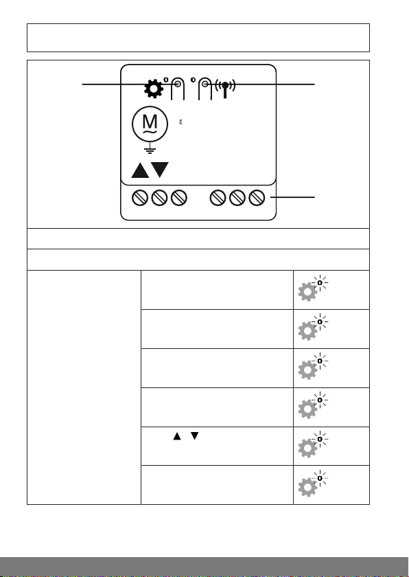
Explanation of displays and buttons........................................................... 8
Explanation of functions ........................................................................... 9
Wiring ....................................................................................................10
Compatible Centronic transmitters ...........................................................12
Switching between operating modes ........................................................13
Resetting the operating mode ..................................................................14
Commissioning with a CentronicPLUS transmitter .....................................15
Explanation of symbols .....................................................................15
Programming the CentronicPLUS transmitter .....................................16
Selection of the receiver for the setting mode .....................................19
Changing direction of rotation via the transmitter ................................21
Adding additional transmitters to the installation .................................22
Setting the travel path .......................................................................23
Deleting the travel path .....................................................................24
Intermediate positions I + II................................................................25
Setting/adjusting the maximum tilt (venetian blind operation)...............27
Manually adjusting the slat position....................................................28
Switching actuator operating mode....................................................28
Commissioning with a Centronic transmitter..............................................30
Explanation of symbols .....................................................................30
Programming the Centronic transmitter .............................................30
Changing direction of rotation via master transmitter...........................33
Deleting transmitters ........................................................................34
Overwriting the master transmitter .....................................................35
Setting the travel path with a Centronic transmitter..............................37
Deleting the travel path with a Centronic transmitter ............................38
Intermediate positions I + II................................................................38
Setting/adjusting the maximum tilt (venetian blind operation)...............40
Switching actuator operating mode....................................................40
Additional functions with CentronicPLUS/ Centronic .................................42
Programming the run times ...............................................................42
Deleting the run times with a CentronicPLUS transmitter......................43
Deleting the run times with a Centronic transmitter..............................43
2-en

3-en
Activating/ deactivating the run times with a CentronicPLUS transmitter
.......................................................................................................44
Activating/ deactivating the run times with a Centronic transmitter .......44
Restoring the factory settings for the radio programming.....................45
Disposal .................................................................................................45
Technical data ........................................................................................46
What to do if...?.......................................................................................47
Simplified EU declaration of conformity.....................................................48

General
The radio receiver, delivered ex works, converts radio signals into control sig-
nals. A wired drive can be radio-controlled using the radio receiver. The radio
receiver can be controlled with all transmitters in the CentronicPlus range of
control units and with various transmitters in the Centronic range of control
units (see Compatible Centronic transmitters [}12]).
Please observe these Assembly and Operating Instructions when installing
and setting up the equipment.
Explanation of pictograms
CAUTION CAUTION indicates a hazardous situation
which, if not avoided, could result in in-
jury.
ATTENTION ATTENTION indicates measures that must
be taken to avoid damage to property.
Denotes user tips and other useful in-
formation.
4-en

Licensing information for open source
software
This device uses free/open source software.
The licence texts are enclosed with the product in the licence documentation,
which can be identified by the following symbol:
The licence texts for the licensed software being used can be downloaded
from www.becker-antriebe.com/licenses.
Written request for the licence texts:
Becker-Antriebe will, on request, provide the licence texts for the licensed
software being used at cost price, either on a USB stick or a similar data car-
rier. Please send an email to the following email address for more information:
licenses@becker‑antriebe.com
Warranty
Structural modifications and incorrect installation which are not in accordance
with these and our other instructions can result in serious injuries, e.g., crush-
ing of limbs. Therefore, structural modifications may only be carried out with
our prior approval and strictly in accordance with our instructions, particularly
the information contained in these Assembly and Operating Instructions.
Any further processing of the products which does not comply with their inten-
ded use is not permitted.
The end product manufacturer and fitter have to ensure that all the relevant
current statutory, official and, in particular, EMC regulations are adhered to
during utilisation of our products, especially with regard to end product manu-
facture, installation and customer advice.
5-en

Safety instructions
The following safety instructions and warnings are intended to avert hazards
and to prevent property damage and personal injury.
General information
•Always comply with regulations of local energy supply companies as well
as VDE 100 provisions for wet and damp rooms during installation.
•Only use in dry rooms.
•Only use unmodified original parts from the control unit manufacturer.
•Observe all pertinent country-specific regulations.
•Keep people out of the system’s range of travel.
•If the system is controlled by one or several appliances, the system’s
range of travel must always be visible during operation.
•Keep children away from control units.
Caution
•Risk of injury due to electric shock.
•Connections to the 230 V mains must always be per-
formed by a specialist.
•Disconnect the connecting cable from the power prior to
installation.
•When connecting the control cables , only use cables with
sufficient electrical strength.
6-en

Intended use
The radio receiver described by the present instructions must only be used for
the operation of roller shutter, awning, blind and lighting control units.
•Please note that radio-controlled systems may not be used in areas with
a high risk of interference (e.g. hospitals, airports).
•The remote control is intended solely for use with equipment and sys-
tems in which malfunctions in the transmitter or receiver would not pose
any risk to persons, animals or property, or which contain safety devices
to eliminate such risks.
•The operator is not protected from interference from other telecommu-
nications systems and terminal equipment (e.g. even from radio-con-
trolled systems which are properly operated in the same frequency
range).
•Only connect radio receivers to devices and systems approved by the
manufacturer.
•Ensure that the control unit is not installed or operated
close to metal surfaces or magnetic fields.
•Radio-controlled systems transmitting on the same fre-
quency may cause reception interference.
•Note that the range of the radio signal is limited by legis-
lation as well as by design.
7-en

Explanation of displays and buttons
C L L N
µ 3A 110-240V~
µ 3A 30V
1
2
3
1 Programming button
2 Connecting terminals
3 Mode button Roller shutter (factory setting)
1x
Sun protection
2x
Venetian blind
3x
Switching actuator
4x
Pulse /
5x
Pulse
6x
8-en

Explanation of functions
Outputs
Connect the drive to the outputs of the device. The arrows on the device show
the direction in which the drive turns.
Roller shutter operation
By pressing a travel button, the roller shutter moves to the set limit position.
Awning operation
By pressing a travel button, the awning moves to the set limit position.
Venetian blind operation
In venetian blind operation, the current slat tilt is saved as well as the interme-
diate positions I + II. The saved tilt is applied when moving to the respective in-
termediate position.
Switching actuator operation
Pressing a travel button switches the consumer on, and the stop button on the
transmitter switches it off. In switching actuator mode, the device behaves dif-
ferently to the previous operating modes.
Impulse mode /
Pressing a travel button connects the corresponding output / for 0.6s
and pressing the stop button on the transmitter connects the output in the dir-
ection of the last operation for 0.6s.
Impulse mode
Pressing the , or STOP button switches the relay in the direction for
1s. Adjusting the running time is not possible in this operating mode.
9-en

Wiring
Caution
•Risk of injury due to electric shock.
•Connection may only be performed by a qualified electri-
cian!
•The device only offers back-of-hand protection, not
touch protection.
•If two or more drives are going to be operated via the ra-
dio receiver, the drives must be decoupled by relay con-
trols. There is no need for decoupling in the case of our
drives with electronic limit switching.
•Always take into account the device switching current.
Attention
Make sure that the drive limit positions have been set.
Sample wiring diagram with a 230 V AC tubular drive
1. Connect the device as follows:
C L L N
µ 3A 110-240V~
µ 3A 30V
2. When the power is switched on, the device confirms by briefly switching in
the UP direction.
10-en

3. Set the operating mode as described in the chapter Switching between op-
erating modes [}13]
4. Programme a transmitter into the receiver.
Sample wiring diagram with a 24 V DC tubular drive
1. Connect the device as follows:
BU (1)
24 V
+
BN (2) BK (3) RD (4)
-
C L L N
µ 3A 110-240V~
µ 3A 30V
2. When the power is switched on, the device confirms by briefly switching in
the UP direction.
3. Set the operating mode as described in the chapter Switching between op-
erating modes [}13].
4. Programme a transmitter into the receiver.
11-en

Compatible Centronic transmitters
All CentronicPlus receivers can be operated with the Centronic transmitters
listed in the Centronic/CentronicPlus compatibility table at
www.becker-antriebe.com/downloads
As two fundamentally different radio technologies are linked in this case, the
full performance of the CentronicPlus radio control system is not available in
this combination. When using the Centronic transmitter with CentronicPlus re-
ceiver, the range performance may be reduced under certain circumstances.
A Centronic transmitter cannot process feedback from the CentronicPlus re-
ceiver. The full performance of CentronicPlus is only achieved in combination
with CentronicPlus transmitters, receivers and sensors, as only then will an in-
telligent, bidirectional system be automatically created.
12-en

Switching between operating modes
The running time, tilt, intermediate positions, direction of ro-
tation, programmed transmitter and installation data are de-
leted when changing operating mode.
Briefly pressing the mode button on the radio re-
ceiver causes the adjacent LED to flash orange to
indicate the current operating mode.
►
LED flashes 1x:
Roller shutter
►
LED flashes 2x:
Sun protection
►
LED flashes 3x:
Venetian blind
►
LED flashes 4x:
Switching actuator
►
LED flashes 5x:
Pulse /
►
LED flashes 6x:
Pulse
Keep the mode button pressed down to switch to
the next operating mode. Briefly pressing the
mode button again switches to the next operating
mode, and so on. Once the required operating
mode has been selected, wait a moment until the
LED next to the mode button confirms the pro-
gramming by lighting up green.
13-en

Resetting the operating mode
The running time, tilt, intermediate positions, direction of ro-
tation, programmed transmitter and installation data are de-
leted when resetting the operating mode.
Press the mode button until the adjacent LED
starts to flash red and then lights up green. Re-
lease the button as soon as the LED lights up
green.
►
The operating mode has been reset and the
radio receiver switches to programming
mode.
14-en

Commissioning with a CentronicPLUS
transmitter
Explanation of symbols
Up/retract button
STOP button
Down/extend button
Programming button (on the transmitter)
Programming button (on the radio receiver)
Mode button (on the radio receiver)
LED ring on the transmitter (only when using a
CentronicPlus transmitter. Feedback is not
sent to the transmitter when using a
Centronic transmitter)
Receiver confirms once or multiple times by
switching outputs or by the mode LED illumin-
ating
Operating modes
Normal mode Control of selected receiver/ channel
Receiver selection Selection of the required receiver and chan-
nel allocation
Setting mode Commissioning and administration of selec-
ted receivers
15-en

Programming the CentronicPLUS transmitter
Caution
•Risk of injury due to electric shock.
•Connection may only be performed by a qualified electri-
cian!
•The device only offers back-of-hand protection, not
touch protection.
Establish programming mode
Make sure that the required operating mode is selected.
Putting the radio receiver into programming mode by switching on the
power
Switch on the power.
▻
The LED next to the programming but-
ton flashes green and then flashes or-
ange after 3 minutes.
▻
The receiver confirms.
►
The radio receiver remains in programming
mode for 15minutes.
Putting the radio receiver into programming mode with the program-
ming button
Briefly press the programming button on the radio
receiver.
▻
The LED next to the programming but-
ton flashes green and then flashes or-
ange after 3 minutes.
►
The radio receiver remains in programming
mode for 15minutes.
16-en

With brand new products, devices from another installation
or products that have been restored to factory settings, pro-
gramming mode must be established beforehand (see Estab-
lishing programming mode).
Bring the transmitter as close as possible to the
receiver to be programmed.
3s Press the programming button for 3 seconds
when it is ready to program. The transmitter per-
forms a search and the LED ring continuously
changes colour. The transmitter then switches to
receiver selection and selects the receiver with the
best connection quality.
▻
The receiver confirms.
If you do not receive confirmation from the re-
quired receiver, you can press the / button to
toggle between the available receivers until the re-
quired receiver confirms. Pressing the button
for 3 seconds confirms the receiver with the best
connection quality.
▻
The transmitter displays the current as-
signment status of the receiver via the
LED ring.
Assignment status
Lights up yellow: The receiver is not yet part of the installation or is
in the as-delivered condition.
Lights up blue: The receiver is not assigned to the selected
channel.
Lights up green: The receiver is assigned to the selected chan-
nel.
Lights up white: Centronic PLUS sensor selected.
Lights up purple Centronic PLUS transmitter selected.
Lights up red: No receiver located.
17-en

Select the desired channel by pressing the func-
tion key on the multi-channel hand-held transmit-
ter.
or
Press the STOP button to change the assignment
status of the selected receiver. If the receiver is
not yet part of the installation, it will be added and
assigned to the selected channel.
▻
The receiver signals once to confirm
the channel assignment, or signals
twice to cancel the channel assign-
ment.
▻
The transmitter lights up accordingly to
confirm the new assignment status.
►
The receiver is now part of the installation
with the required channel assignment.
3s Then press the programming button for 3seconds
to change to normal mode.
►
The LED ring goes out.
18-en

Selection of the receiver for the setting mode
Bring the transmitter as close as possible to the
required receiver.
3s Press the programming button for 3seconds. The
transmitter performs a search and the LED ring
continuously changes colour. The transmitter then
switches to receiver selection and selects the re-
ceiver with the best connection quality.
▻
The receiver confirms.
If you do not receive confirmation from the re-
quired receiver, you can press the / button to
toggle between the available receivers until the re-
quired receiver confirms. Pressing the button
for 3 seconds confirms the receiver with the best
connection quality.
▻
The transmitter displays the current as-
signment status of the receiver via the
LED ring.
Assignment status
Lights up yellow: The receiver is not yet part of the installation or is
in the as-delivered condition.
Lights up blue: The receiver is not assigned to the selected
channel.
Lights up green: The receiver is assigned to the selected chan-
nel.
Lights up white: Centronic PLUS sensor selected.
Lights up purple Centronic PLUS transmitter selected.
Lights up red: No receiver located.
19-en

Briefly press the programming button to change
to the setting mode.
▻
The receiver confirms.
▻
The LED ring of the transmitter slowly
pulses light blue.
▻
The receiver now enters dead-man
mode.
►
The setting mode is now active.
If a receiver has not yet been added to the
installation (LED ring lights up yellow), it will
not be possible to select it in this way. The re-
ceiver must be added to the installation be-
forehand. See chapter “Programming
CentronicPLUS transmitters”.
20-en
Table of contents
Other Becker Radio manuals