Trio CS-2100A User manual
CS-2100A
100MHz
4-CHANNEL
OSCILLOSCOPE
INSTRUCTIONMANUAL
TRIO-KENWOODCORPORATION
DELAYEDSWEEPOSCILLOSCOPE
CS-2100A
100MHz4-CHANNEL
OSCILLOSCOPE
INSTRUCTIONMANUAL
TRIO
CONTENTS
FEATURES1-1
SPECIFICATIONS2-1
PRECAUTIONFORUSE2-3
CONTROLSANDINDICATORS
FRONT
PANEL3-1
SIDE
PANELANDREARPANEL3-5
BOTTOMPANEL3-6
OPERATION
[1]
NORMALSWEEPDISPLAYOPERATION4-1
12]
MAGNIFIEDSWEEPOPERATION4-2
[3]
DELAYEDSWEEPOPERATION4-2
14]
ALTERNATINGSWEEPOPERATION4-3
15]
DUALSWEEPOPERATION4-3
[6]
X-YOPERATION4-4
[7]
SINGLESWEEPOPERATION4-4
[8]
DUALANDQUADTRACEOPERATION4-4
[9]
CASCADEDOPERATION4-4
APPLICATION
ADJUSTMENTSREQUIREDBEFORESTARTING
MEASUREMENT5-1
PROBECOMPENSATION5-1
TRACEROTATIONCOMPENSATION5-1
MEASUREMENTS5-1
DC
VOLTAGEMEASUREMENTS5-1
MEASUREMENTOFTHEVOLTAGEBETWEEN
TWOPOINTSONA WAVEFORM5-2
ELIMINATIONOFUNDESIRED
SIGNALCOMPONENTS5-2
TIME
MEASUREMENTS5-3
FREQUENCYMEASUREMENTS5-3
PULSEWIDTHMEASUREMENTS5-4
PULSERISETIMEANDFALLTIME
MEASUREMENTS5-4
TIME
DIFFERENCEMEASUREMENTS5-5
PHASEDIFFERENCEMEASUREMENTS5-6
RELATIVEMEASUREMENTS5-6
PULSEJITTERMEASUREMENTS5-8
SWEEPMULTIPLICATION5-8
DELAYEDSWEEPTIMEMEASUREMENTS5-9
PULSEWIDTHMEASUREMENTSUSING
DELAYEDSWEEP5-9
FREQUENCYMEASUREMENTSUSING
DELAYEDSWEEP5-10
PULSEREPETITIONTIME5-10
USING
DELAYEDSWEEPFORMEASUREMENT
OF
RISETIMESANDFALLTIMES5-11
TIME
DIFFERENCEMEASUREMENTS
USING
DELAYEDSWEEP5-11
X-YOPERATION5-12
QUADTRACEOPERATION5-13
DUALSWEEPOPERATION5-13
INSTALLINGPROBEHOLDER6-1
INSTALLINGACCESSORYBAG6-1
CIRCUITDESCRIPTION7-1
BLOCKDIAGRAM7-5
MAINTENANCE8-1
REMOVALOFCASE8-1
REMOVING/INSTALLINGCRT8-1
TROUBLESHOOTING8-1
REPLACINGSWITCHING
POWERSUPPLY8-2
REPLACINGBATTERY8-2
FEATURES
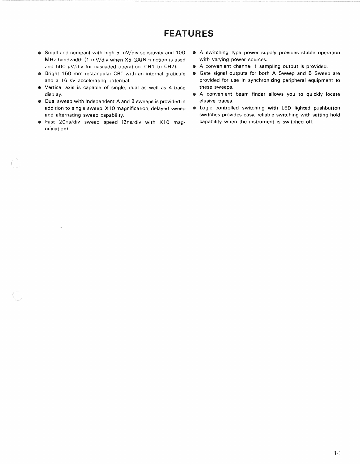
•Smallandcompactwithhigh5 mV/divsensitivityand100
MHzbandwidth(1mV/divwhenX5GAINfunctionisused
and500^V/divforcascadedoperation,CH1toCH2).
•Bright150mmrectangularCRTwithaninternalgraticule
anda
1
6 kVacceleratingpotential.
•Verticalaxisiscapableofsingle,dualaswellas4-trace
display.
•DualsweepwithindependentA andB sweepsisprovidedin
additiontosinglesweep,X10magnification,delayedsweep
andalternatingsweepcapability.
•Fast20ns/divsweepspeed(2ns/divwithX10mag-
nification).
•A switchingtypepowersupplyprovidesstableoperation
withvaryingpowersources.
•A convenientchannel1 samplingoutputisprovided.
•GatesignaloutputsforbothA SweepandB Sweepare
providedforuseinsynchronizingperipheralequipmentto
thesesweeps.
•A convenientbeamfinderallowsyoutoquicklylocate
elusivetraces.
•LogiccontrolledswitchingwithLEDlightedpushbutton
switchesprovideseasy,reliableswitchingwithsettinghold
capabilitywhentheinstrumentisswitchedoff.
1-1

SPECIFICATIONS
CRT
Model:
150ATM31A
Displayarea:8 X 10div(1div=1 cm)
Type:
Rectangular,withinternal
graticule
Acceleratingpotential:
1
6kV
VERTICALAXIS(Channel1 andChannel2 identical
specifications)
Sensitivity:5 mV/divto5V/div(X1mode)
1mV/divto
1
V/div(X5mode)
500^ V/div(Cascadedoperation,
CH
1
toCH2)
Accuracy:±3%(10~ 35°C)
±5%
(0~ 50°C)
±8%
(Cascadedoperation,
CH
1
toCH2)
Attenuator:5 mV/divto5V/divin
1
-2-5
sequence,all10rangeswith
fineadjustment.
Inputresistance:1 M0±2%(1M0mode)
5012±2%(500mode)
Inputcapacitance:Approx.28pF
Frequencyresponse:(Includex 5 GAINmode)
DC:
DCto100MHz(-3dB)
DCto120MHz(-6dB)
DCto70MHz(-3dB),
(Cascadedoperation,CH1toCH2)
AC:
5 Hzto100MHz(-3dB)
5Hzto120MHz(-6dB)
7Hzto70MHz(-3dB),
(Cascadedoperation,CH1,toCH2)
Risetime:
3.5ns
Signaldelaytime:Approx30nsasdisplayed
onCRTscreen
Crosstalk:—40dBminimum
Operatingmodes:
CH1CH1,singletrace
CH2CH2,singletrace
DUALCH
1
andCH2,dualtrace
ADDCH
1
+ CH2(added)display
QUADCH
1
~ CH4.fourtrace
ALTTwoorfourwaveforms,
alternating
CHOPTwoorfourwaveforms,chopped
CHOPfrequency:Approx250kHz,switchable
Polarityreversal:CH2only
Maximuminputvoltage:500Vp-por250V(DC+ AC
peak)in1 M0mode.
5VrmsorDC±5Vin500mode.
Maximumundistorted
amplitude:8 division,minimum(DCto
100MHz)
Bandwidthlimiting:Verticalsystembandwidth
withthe20MHzBWpushbutton
switchpushedisapproximately
20MHz
VERTICALAXIS(Channel3 andChannel4 common
specifications)
Sensitivity:0.1V/div.
1
V/div±3%
Attenuator:1/1,1/10
Inputresistance:1 M0±2%
Inputcapacitance:Approx.28pF
Inputcouplingmode:DConly
Frequencyresponse:DCto
1
00MHz(—3dB)
DCto120MHz(-6dB)
Risetime:
3.5ns
Signaldelaytime:SameasCH
1
andCH2
Maximumallowablevoltage
DCcomponent:±0.5Vorless(AC-+-DC)
(±5V,1/10attenuated)
ACcomponent:1 Vp-p(10Vp-p,1/10 attenuated)
orless
Maximuminputvoltage:50V(DC-+-ACpeak)
HORIZONTALAXIS(CH2input)
Modes:X-Ymodeisswitchselectable
(HORIZONTALDISPLAY)
X-Ymode:CH1:Y-axis
CH2:
X-axis
Sensitivity:SameasCH2
Accuracy:SameasCH2
Inputresistance:SameasCH2
Inputcapacitance:SameasCH2
Frequencyresponse:
DC:
DCto5 MHz(-3dB)
DCto6 MHz(-6dB)
AC:
5 Hzto5 MHz(-3dB)
5Hzto6 MHz(-6dB)
X-Yphasedifference:Lessthan3°at100kHz
SWEEP
Modes(switchablewiththeHORIZONTALDISPLAYswitch):
AA Sweep
ALTB Sweepwaveformisdisplayedas
anintensifiedportionofthe
ASweepandB Sweepalternating
A-INT-BDurationoftheB Sweepisdisplayed
asanintensifiedportionof
theA Sweep.
BDLY'DDelayedB sweep
DUALDualsweep— A andB sweeps,
independently
X-YX-Ydisplaymode
2-1

SPECIFICATIONS
ASweeptime:20ns/div
to
0.5s/div
in23
ranges,
in
1
-2-5
sequence,
verniniercontrolprovides
fullyadjustablesweeptime
betweensteps.
BSweeptime:20ns/div
to
50ms/div
in20
ranges,
in
1
-2-5
sequence.
Accuracy:
+3%(10~
35°C)
±6%(0~50°C)
Sweepmagnification:
X10
±5%
(10~
35°C)
±7%
(0~
50°C)
Linearity:20ns/div
to
0.5s/div
±3%
(±5%
with
X10
magnification)
HOLDOFF:Continuouslyadjustable
forA
Sweephold
off
timefrom
NORM
toX5.
Traceseparation:
B
positionable
upto4
divisionsseparatedfrom
A
Sweep,continuouslyadjustable.
Delaymethod:Continuousdelay.SYNCdelay
Delaytime:
0.2to10
times
the
sweeptime
from200ns
to
0.5s,
continu-
ouslyadjustable.
Timedifferencemeasurementaccuracy:
±2%
(10
~ 35°C)
±4%(0
~
50°C)
Delayjitter:
1
/20000
of
the
fullscale
sweeptime.
TRIGGERING
ATRIG
Atriggermodes:AUTO.NORM,SINGLE,
FIX:
at
the
center
of
the
waveform
Triggersource:
V
MODE.
CH1,CH2.(EXT)
CH3
1/1and
1/10
Couplingmodes:
AC,
LFREJ,
HFREJ,
DC,
VIDEO
VIDEO-LINEsyncautomatically
selected
at
sweeptimes
of
50yus/div
to
20ns/div.
VIDEO-FRAMEsyncautomatically
selected
at
sweeptimes
of0.5s/div
to
0.1
ms/div.
Triggerlevel:±90°adjustable
Polarity:
+/
—
BTRIG
BtriggermodesSTARTSAFTERDELAY,
TRIGGERABLEAFTERDELAY
Triggersource:
CH1,CH2,(EXT)CH4
1/1and
1/10
Coupling
modes:AC,
LFREJ,
HFREJ,
DC
Triggerlevel:±90°adjustable
Polarity:
+ /
—
Triggersensitivity
(A
and
B)
COUPLING FREQRANGE MINIMUMSYNCAMPLITUDE
COUPLING FREQRANGE INT EXT EXT1
10
DC DC
- 20
MHz
DC
- 50
MHz
DC
-
100MHz
05div
1Odiv
15div
50mV
100
mV
150
mV
05V
1
OV
1
5V
AC Same
asforDCbut
withincreasedminimumlevel
for
below
20Hz
AC
HFn[j Increasedminimumlevelbelow
20
HZ
and
above
30
KHZ
AC
LFfuj
Increasedminimumlevelbelow
30kHz
VIDEO FRAMELINE 05div 50
mV
0
5V
AUTO:
Same
as
abovespecifications
for
above
30Hz.
FIX:
40
Hz~20
MHz1.0div(100mV)
40Hz'vSO
MHz1.5div
(150
mV)
Jitter:0.5nsmaximum
at
1
00
MHz
at
2ns/divsweeprate
(X1
0
MAG
on)
CALIBRATINGVOLTAGE
AND
CURRENT
1
kHz±3%
Positivesquarewave
0.3V±1%
(10
- 35C)
+
2%
(0- 50C)
10mA
±2%(10
- 35C)
±4%
(0- 50C)
INTENSITYMODULATION
Inputsignal:
TTL
level,intensityincreasing
withmorepositivelevels
Inputimpedance:Approx.
10kO
Usablefrequencyrange:DCto
10
MHz
Maximuminputvoltage:
50V
(DC
+ AC
peak)
VERTICALAXISOUTPUTSampled
CH1
output
Outputvoltage:
50
mVp-p/div(into
500
load)
Outputimpedance:Approx.
500
Frequencyresponse:
DCto100MHz(
—
3 dB)
(into
500
load)
GATEOUTPUT
(AandB)
Outputvoltage:Approx.
1.5V
positivegate
(into5000load)
TRACEROTATIONElectrical,adjustable
POWERSUPPLY
Linevoltage:
LOW:90- 132V
HIGH:
180~
264V
Linefrequency.50/60
Hz
Powerconsumption:Approx.
56W
DIMENSIONS
Width:
284mm
(328
mm)
Height:
138mm
(150
mm)
Depth:
400mm
(471mm)
(
)
dimensionsincludepro-
trusionsfrombasiccaseout-
linedimensions.
2-2
SPECIFICATIONS
WEIGHT7 4 kg
ACCESSORIES
PC-29Probes2
InstructionManual1
HandBook1
ACpowercord1
PanelCover1
Probeholder1
OPTION
AccessoryBag(MC-78)
PRECAUTIONSFORUSE
1)Donotapplyinputvoltageexceedingtheirmaximum
ratingand. neverapplyexternalvoltagetotheinput
terminals.
CH
1
andCH2:
1Mil. 500Vp-por250V(DC+ ACpeak)
500:
5VrmsorDC±5V
CH3andCH4:50V(DC•+-ACpeak)
Z-axisInput:50V(DC+ ACpeak)
2)Thefollowingconditionsshouldbeavoided:
(a)Directsunlight
(b)Hightemperaturesandhumidity
(c)Mechanicalvibration
(d)Proximitytoelectricalnoiseortransientgenerating
machinery.
3)Donotusemorethantherequiredbeamintensity.
4)Donotleavethebeamstationaryforlongperiods.
5)TheCS-2100Amakesuseofinternalbatterywhich,if
depleted,
cancausethepanelLED'snottolightupontur-
ningtheunitON.Ifthisoccurs,refertotheinstruction
manualforinstructionsonreplacingthebattery.
6)Topreventelectricalshocks,besuretoconnecttheGND
terminaltoanappropriateearthpoint.
7)Coolingprecautions.
TheCS-2100Aisprovidedwitha convenientcarrying
han-
dlewhichdoublesasa standtoadjusttheviewingangle.
Whileanyarbitraryanglemaybeset,besurethatnoob-
jectsareallowedtorestonthetopoftheunitorthatthe
coolingventsarenotblocked,sincethiswillcauseanun-
duetemperatureriseintheCS-2100A.
8)SincetheCS-2100Amakesuseofhighvoltagecircuitry,if
removingthecase,refertothe"MAINTENANCE"for
removingthecase.
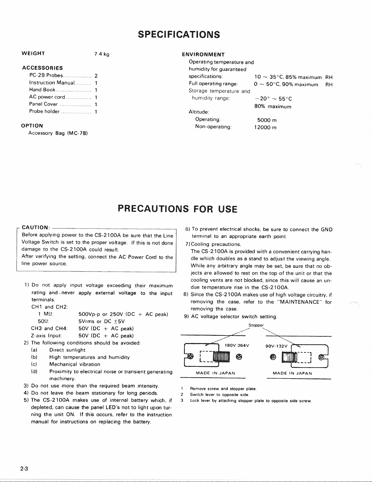
9)ACvoltageselectorswitchsetting.
Stopper
MADEINJAPAN MADEINJAPAN
1Removescrewandstopperplate.
2Switchlevertooppositeside.
3Lockleverbyattachingstopperplatetooppositesidescrew.
2-3
ENVIRONMENT
Operatingtemperatureand
humidityforguaranteed
specifications:10~ 35°C,85%maximumRH
Fulloperatingrange:0 ~ 50°C,90%maximumRH
Storagetemperatureand
humidityrange:—20°~ 55°C
80%
maximum
Altitude:
Operating:5000m
Non-operating:12000m
CAUTION:
BeforeapplyingpowertotheCS-2100AbesurethattheLine
VoltageSwitchissettothepropervoltage.Ifthisisnotdone
damagetotheCS-2100Acouldresult.
Afterverifyingthesetting,connecttheACPowerCordtothe
linepowersource.
CONTROLSANDINDICATORS
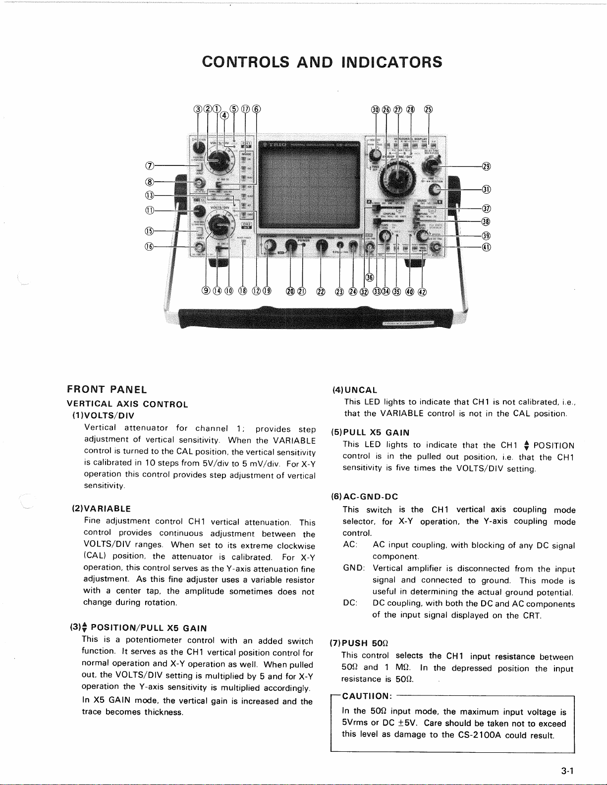
FRONTPANEL
VERTICALAXISCONTROL
(DVOLTS/DIV
Verticalattenuatorforchannel1;providesstep
adjustmentofverticalsensitivity.WhentheVARIABLE
controlisturnedtotheCALposition,theverticalsensitivity
iscalibratedin10stepsfrom5V/divto5 mV/div.ForX-Y
operationthiscontrolprovidesstepadjustmentofvertical
sensitivity.
(2)VARIABLE
FineadjustmentcontrolCH1verticalattenuation.This
controlprovidescontinuousadjustmentbetweenthe
VOLTS/DIVranges.Whensettoitsextremeclockwise
(CAL)position,theattenuatoriscalibrated.ForX-Y
operation,
thiscontrolservesastheY-axisattenuationfine
adjustment.Asthisfineadjusterusesa variableresistor
witha centertap,theamplitudesometimesdoesnot
changeduringrotation.
(3)$ POSITION/PULLX5GAIN
Thisisa potentiometercontrolwithanaddedswitch
function.
ItservesastheCH1verticalpositioncontrolfor
normaloperationandX-Yoperationas
well.
Whenpulled
out,theVOLTS/DIVsettingismultipliedby5 andforX-Y
operationtheY-axissensitivityismultipliedaccordingly.
InX5GAINmode,theverticalgainisincreasedandthe
tracebecomesthickness.
(4)UNCAL
ThisLEDlightstoindicatethatCH1isnotcalibrated,i.e.,
thattheVARIABLEcontrolisnotintheCALposition.
(5)PULLX5GAIN
ThisLEDlightstoindicatethattheCH1$ POSITION
controlisinthepulledoutposition,i.e.thattheCH1
sensitivityisfivetimestheVOLTS/DIVsetting.
(6)AC-GND-DC
ThisswitchistheCH1verticalaxiscouplingmode
selector,forX-Yoperation,theY-axiscouplingmode
control.
AC:
ACinputcoupling,withblockingofanyDCsignal
component.
GND:
Verticalamplifierisdisconnectedfromtheinput
signalandconnectedtoground.Thismodeis
usefulindeterminingtheactualgroundpotential.
DC:
DCcoupling,withboththeDCandACcomponents
oftheinputsignaldisplayedontheCRT.
(7)PUSH5012
ThiscontrolselectstheCH1inputresistancebetween
50i2and1 Mfi.Inthedepressedpositiontheinput
resistanceis5012.
I—CAUTIION:
Inthe50Q inputmode,themaximuminputvoltageis
5VrmsorDC±5V.Careshouldbetakennottoexceed
thislevelasdamagetotheCS-2100Acouldresult.
3-1
CONTROLSANDINDICATORS
(8)INPUT
CH1verticalinputconnector;servesalsoastheY-axis
inputconnectorforX-Yoperation.
(9)VOLTS/DSV
Verticalattenuatorforchannel2;providesstep
adjustmentofverticalsensitivity,VARIABLEcontrolistur-
nedtotheCALposition,theverticalsensitivitycalibrated
in10stepsfrom5V/divto5 mV/div.ForX-Yoperation
thecontrolprovidesstepadjustmentofhorizontal
sensitivity.
(10)VARIABLE
CH2verticalattenuationfineadjustment.Operationis
similartothatoftheCH
1
VARIABLEcontrol.ForX-Y
operationthecontrolservesastheX-axisattenuationfine
adjustment.
(11)$ POSITIONX-Y^•/PULLX5
GAIN
Dualcontrolwhichfunctionssimilarlytothecorresponding
CH1control.Inaddition,itservesasthehorizontal
positioncontrolandX-axissensitivitymagnifierforX-Y
operation.
(12)UNCAL
UNCALdisplayforCH2verticalaxisorfortheX-axisfor
X-YoperationwhenCH2VARIABLEcontrolisnotinCAL
position.
(13)PULLX5GAIN
ThisdisplayLEDindicatesthatX5magnificationisineffect
fortheCH2verticalaxisfornormaloperationorthatitisin
effectfortheX-axisforX-Yoperation.
(14)AC-GND-DC
ThisswitchsetstheCH2verticalaxisinputcouplingmode
ortheX-axiscouplingmodeforX-Yoperation.Its
operationissimilartothatofthecorrespondingcontrolfor
CH1.
(15)PUSH5012
ThisswitchselectstheCH2inputresistancebetween
5012and1 MS2.ItservestosimilarlyswitchtheX-axis
inputresistanceforX-Yoperation.Operationisthesame
asforthecorrespondingCH
1
control.
r-CAUTION:
Thesame5VrmsorDC±5VlimitationappliestotheCH2
inputwhenusingthe50J2inputresistancemodeas
discussedaboveforCH1.
(16)INPUT
CH2verticalinputconnector;servesalsoastheX-axis
inputconnectorforX-Yoperation.
(17)MODE
Verticalaxismodeselectionswitches.
CH1DisplayofCH1inputsignalonly.
CH2DisplayofCH2inputsignalonly.
DUALDisplayofbothCH
1
andCH2.Forthismode
eitherCHOPorALTmodewillbeineffect,
selectedbythesimilarlynamedswitches.
ADDDisplayofthealgebraicsumofCH
1
+ CH2
or,ifCH2hasbeeninverted,thedifferenceof
CH1- CH2.
QUADDisplayofCH1throughCH4inputsignals.For
thismodeaswellasforDUAL,eithertheALT
orCHOPmodeisapplicableandselectedby
theappropriatelynamedswitch.
ALTWhenDUALorQUADmodehasbeen
selected,
2 or4 signalinputsaredisplayedin
analternatingfashion.
CHOPSimilartoALTbutinputsignalsaredisplayed
ina choppedfashion.
CH2INVThisswitchinvertsthepolarityoftheCH2
inputsignal.
20MHzBWThisswitchwhentheLEDisindicated,
limitstheverticalbandwidthtoapproximately
20MHz.
[-CAUTION:
Thevariousverticalmodesettingsarerelated
tohorizontalmodeandtriggersource.Seethe
sectionsonHORIZONTALDISPLAYand
SOURCEfora descriptionofthisrelationship.
(18)
BEAM
FINDER
Thispushswitchisusedtoshrink'theCRTdisplayto
alloweasylocationofthebeam.
POWERSUPPLY/CRTDISPLAYCONTROLS
(19)A INTENSITY/BINTENSITY
Thisdualcontrolallowsadjustmentofthebeamintensity
fortheA SweepandB Sweeprespectively.
AINTENSITY(centercontrol)
AdjuststhebeamintensityfortheA Sweep
andthedisplayintensityforX-Yoperation.
BINTENSITY(outercontrol)
AdjuststheintensityoftheB Sweepbeam.
(20)
POWER/SCALE
ILLUM
Thiscontrolservesasthepowersupplyswitchaswellas
theadjustmentforthescaleillumination.
(21)LEDPILOTLAMP
Thislampindicatesthatthepowersupplyhasbeenturned
3-2

CONTROLSANDINDICATORS
(22)FOCUS
Thisfocuscontrolcanbeusedtoadjustthebeamfor
optimumfocus.
Auto-Focuscircuitautomaticallyfocusing,oncethis
controlisadjusteditneedsnotbefrequentlyreadjusted.
(23)CAL
Thisisthecalibrationvoltageoutput.0.3Vp-pat1 kHzis
availableintheformofa squarewavesignal.
(24)GN0
Groundterminal— useittoconnecttheinstrumenttothe
earthground.
HORIZONTALAXISCONTROLS
(25)HORIZONTALDISPLAY
Thiscontrolisusedtoselectthehorizontaldisplaymode.
LED'sindicatewhatmodehasbeenselected.
AOnlyA SweepisoperativewiththeB Sweep
dormant.
ALTA SweepalternateswiththeB Sweep.For
thismodeofoperation,theB Sweep
waveformappearsasanintensifiedsectionon
theA Sweep.
A-INT-BDurationoftheB Sweepappearsasan
intensifiedsectionontheA Sweep.
BDLY'DOnlyDelayedB Sweepisoperative.
DUALA SweepandB Sweepoperateinde-
pendently.Forthismodethetwosweepsare
triggeredbytheA TriggersourceandB Trigger
sourcerespectively.
X-YCH1becomestheY-axisandCH2theX-axis
forX-Yoperation.
ThesettingsoftheverticalMODEandTRIG
MODEareineffective.
(26)A SWEEPTIME/DIV,B SWEEPTIME/DIV
ASWEEPTIME/DIVThisoutercontrolisusedtosetthe
ASweeptimein23rangesin1-2-5
sequencefrom20ns/divto0.5s/div.
BSWEEPTIME/DIVThiscentercontrolsetstheB Sweep
timein20rangesin1-2-5sequence
from20ns/divto50ms/div.This
controlisconstructedtomakeit
impossibletosettheB Sweeptime
slowerthantheA Sweeptime.No
fineadjustmentisavailablefortheB
Sweeptime.
(27)A VAR/PULLCHOPF.SELECT
ThiscontrolistheinnermostcontrolontheSWEEP
TIME/DIVcontrol.ItisthefineadjustmentfortheA
Sweeptime.WhenitisturnedfullyclockwisetotheCAL
position,
theA Sweeptimeiscalibratedtothesettingof
theSWEEPTIME/DIVcontrol.
PULLCHOPF.SELECT
Thechoppingfrequencymaybechangedbypullingthis
controloutward.Thisisusefulincaseswheretheinputsi-
gnalissynchronizedtothechoppingfrequency.
(28)UNCAL
ThisLEDlightstoindicatethattheA VARcontrolisnotset
totheCALpositionandthusthattheA Sweeptimeisnot
calibrated.
(29)DELAYTIMEMULTIPLIER
ThiscontroladjuststhestarttimeoftheB Sweeptosome
delaytimeafterthestartoftheSweep.
Thedelaytimemaybesettovaluesbetween0.2and10
timesthesettingoftheA SWEEPTIME/DIVcontrol.
(30)±TRACESEP/HOLDOFF
$TRACESEP
ThisoutercontrolallowstheadjustmentoftheB Sweepupto
4divisionsbelowtheA Sweep,turningthiscontrolto
counterclockwise.ThisknobiseffectivewhentheHorizontal
DisplayissettoALT.EvenwhentheHorizontalDisplayisset
toDUAL,thisknobiseffectivewiththeV modesettoCH1,
CH2orADD.
HOLDOFF
Adualcontrolincorporatinga switchingfunction.
Asa holdoffadjustment,itallowstheadjustmentofthe
timebetweensuccessivesweeps.Turningthecontrol
counterclockwisefromtheNORMpositionlengthensthe
holdofftimeuntiljustbeforetheB ENDSA whenthe
hold-
offtimeismorethan10timestheNORMvalue.
IntheB ENDSA position(fullycounterclockwise),theA
SweepisresetattheendoftheB Sweep.
BENDSA modeisapplicabletotheALT,A-INT-BandB
DLY'DmodesofHORIZONTALDISPLAY.
(31)««*POSITION/FINEPULLX10MAG
Acombinationadjustment/switchcontrol.
ThiscontrolisnotusedforX-Yoperation.
POSITION
Horizontalpositioncoarseadjustment.
FINEPULLX10MAG
Horizontalpositionfineadjustment.Whenthiscontrolis
pulledout,thesweeptimeismade
1
0 timesshorter.
3-3

CONTROLSANDINDICATORS
TRIGGERSOURCECONTROLS
(32)SOURCE
Thiscontrolselects
the
source
fortheA
SweepTrigger.
VMODE
The
triggersource
fortheA
Sweep
is
determi-
ned
bythe
VerticalMODEsetting.
CH1 CH1signal
is
used
asa
triggersource
CH2 CH2signal
is
used
asa
triggersource
ADD Thealgebraic
sumofCH1andCH2
signals
isured
a
signalsource,
(ifCH2has
been
inverted,
the
differencebecomes
the
source.)
DUAL
QUAD
(ALT)
(CHOP)
For
ALT
mode
the
signals
for
CH1through
CH4alternate
asthe
triggersource.
Forthe
CHOPmode
the
choppingsignalbecomes
the
triggersource.
—CAUTION:
.
1
When
the
vertical
MODE
is
selected
in
CHOP,
the
displaycannot
be
synchronizedwith
the
input
signalsince
the
choppingsignalbecomes
the
triggersource.
2.
Triggering
is
impossiblewheninputsignals
arenot
applied
toall
channelswith
the
verticalaxismode
setto
DUAL
or
QUAD.
CH1
CH1
signal
isthe
triggersource
fortheA
Sweep.
CH2
CH2
signal
isthe
triggersource
fortheA
Sweep.
1/1
CH3
signal
isthe
triggersource
fortheA
Sweep.
1/10
The
CH3signal,attenuated
to
1/10
ofits
true
value
isthe
triggersource
fortheA
Sweep.
(34)LEVEL/SLOPEPULL
FIX
LEVEL
Thisoutercontroladjusts
the
level
at
which
theA
trigger
causes
theA
Sweep
be
started.
SLOPEPULL
FIX
Thisinnercontroladjusts
the
slope
oftheA
triggersignal.
When
the
control
is
pulled
outtheFIX
mode
is
selected
for
autoleveladjustment,underwhichcircumstancesouter
TRIGLEVELcontrol
no
longer
hasany
effect.
(35)TRIG'D
Thisgreen
LED
lightswhen
theA
triggersourcesignal
cau-
ses
the
initiation
ofa A
Sweep.
It
lights
forX-Y
operation
as
well.
(36)
CH3orA EXT
TRIG
Inputconnector
fortheCH3
signal.
It
servesalso
asthe
external
A
TRIGinputconnector.
CH3
signal
maybeob-
servedsimultaneouslywith
CH1,2 and4
signalswhen
the
QUADmode
is
selected.
When
the
SOURCEcontrol
issetto
either
EXT(CH3)1/1
or
1/10,the
triggersource
is
thisinputsignal.
(37)SOURCE
Thiscontrolselects
theB
Sweeptriggersource.
CH1
CH1
signal
isthe
triggersource
fortheB
Sweep.
CH2
CH2
signal
isthe
triggersource
fortheB
Sweep.
1/1CH4
signal
isthe
triggersource
fortheB
Sweep.
1/10
TheCH4
signal,attenuated
to1/10ofits
true
value
isthe
triggersource
fortheB
Sweep.
(33)COUPLING
Thiscontrol
is
used
to
select
the
SYNCcoupling
fortheA
trigger.
ACSYNCsignal
isAC
coupledwith
anyDC
com-
ponentblocked.
LFREJ
SYNCsignal
is
coupledthrough
a
high-pass
fil-
ter
to
eliminate
low
frequencycomponents
for
stabletriggering
of
highfrequencysignals.
HFREJ
SYNCsignal
is
coupledthrough
a
low-pass
fil-
ter
to
eliminatehighfrequencycomponents
for
astabletriggering
oflow
frequencysignals.
DC
The
SYNCsignal
isDC
coupled
for
SYNC
whichincludes
the
effects
ofDC
components.
For
CH3andCH4,the
verticalposition
adjustment
hasno
effect
onthe
triggerpoint.
VIDEO
For
synchronization
of
videosignals.
The
posi-
tion
oftheA
SWEEPTIME/DIVcontroldeter-
mineswhetherFRAME
or
LINE
istobe
syn-
ced.
Settingsbetween
0.5sand0.1ms
result
inFRAMEwhilethosebetween
50/isand20
nsresult
in
LINEsync.
(38)COUPLIIMG
Thiscontrolselects
the
SYNCcoupling
fortheB
trigger
group.Operation
is
similar
to
that
ofthe
corresponding
A
SweeptriggercouplingselectcontrolexceptthatVIDEO
is
notavailable.
(39)LEVEL/SLOPEPULLSTARTSAFTERDELAY
LEVEL
Thisoutercontroladjusts
the
level
at
which
theB
trigger
signalcauses
the
start
oftheB
Sweep.
SLOPEPULLSTARTSAFTERDELAY
Thiscontrolselects
the
slope
oftheB
triggersignal.
ForB
triggeroperation
it
must
besetinits
pushed
in
position.
When
itis
pulled
out,theB
Sweepstartsimmediatelyafter
thedelaytimeselected
bythe
DELAYTIMEMULTIPLIER
and
A
SWEEPTIME/DIVcontrol,regardless
ofthe
TRIG
LEVELsetting.Evenwhenthisswitch
isin
positionwith
theTRIGMODE
setto
AUTO,turning
the
LEVEL(outer
knob)fullyclockwise
or
counterclockwiserelease
the
trigger
andsetthe
unit
toB
STARTAFTERDELAYopera-
tion.
3-4
CONTROLSANDINDICATORS
(40)TRIG'D
ThisgreenLEDlightswhentheB triggersourcesignal
cau-
sestheB triggeredsweeptobeinitiated.
(41)CH4or8 EXTTRIG
InputconnectorfortheCH4signal;servesalsoastheB
TRIGexternalinputconnector.CH4signalmaybeobser-
vedsimultaneouslywithCH1,2 and3 signalswhenthe
QUADmodeisselected.WhentheSOURCEselect
con-
trolissettoeitherEXT(CH4)1/1.or1/10,thetrigger
sourceisthisinputsignal.
(42)TRIGMODE
ThiscontrolselectstheTriggerMode.A corresponding
LEDlightstoindicatewhichmodehasbeenselected.
AUTOSweepisinitiatedintriggeredoperationbut
thetraceissweeptevenintheabsenceofa
triggersignal.WhentheHORIZONTAL
DISPLAYissettoDUAL,theB sweepissetto
AUTO.
NORMTriggeredoperationbutnotraceispresented
whena propertriggersignalisnotapplied.
SINGLESinglesweepoperation.Notethatinthismo-
de,
simultaneousobservationofboththeA
andB Sweepsisnotpossible.
rCAUTION:,
Fordualorquadtrace,singlesweepoperation
MODEmustnotbesettoALT.UsetheCHOP
modeinstead.
RESETThisistheresetbuttonforsinglesweepopera-
tion.
ItsLEDremainslighteduntilthemainA
Sweepends.
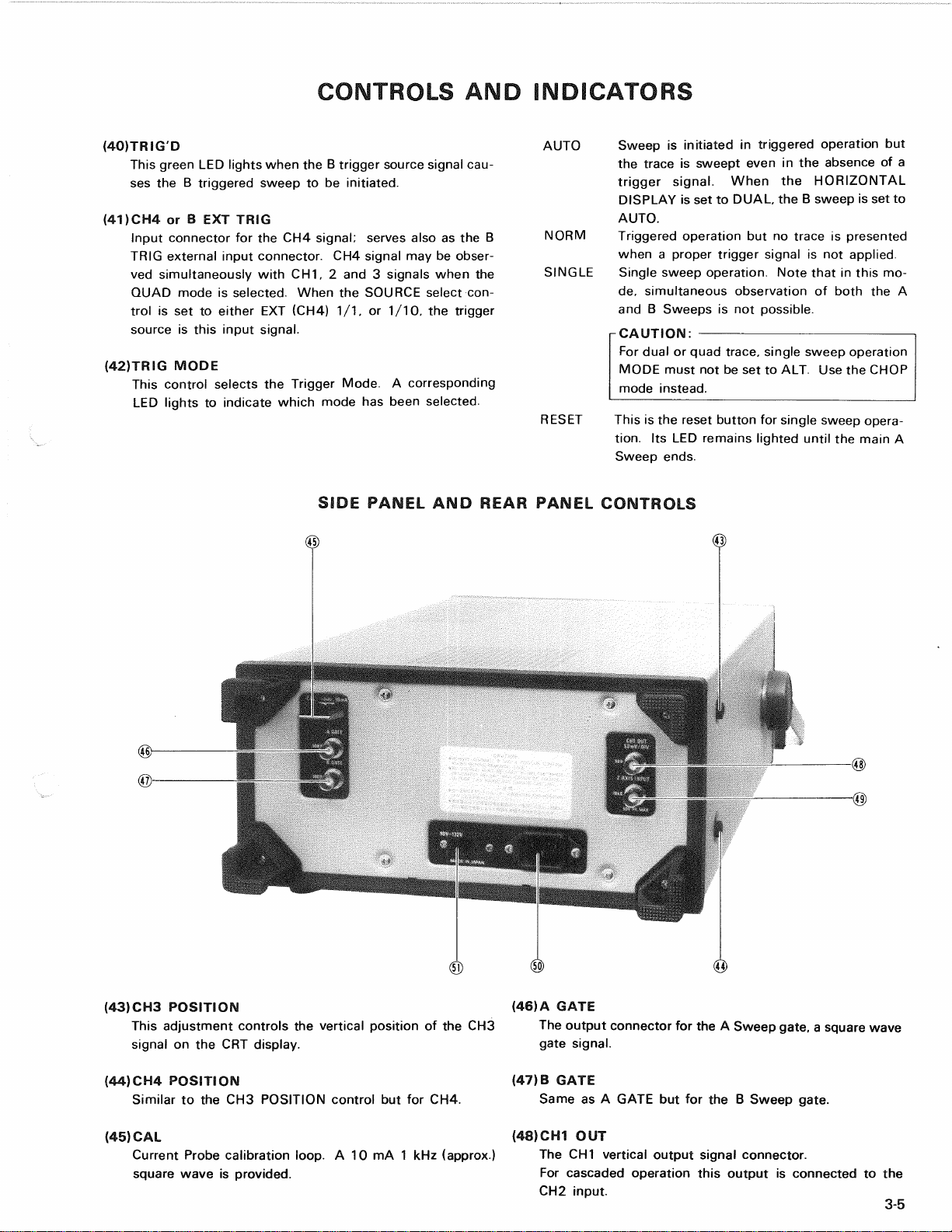
SIDEPANELANDREARPANELCONTROLS
(43)CH3POSITION
ThisadjustmentcontrolstheverticalpositionoftheCH3
signalontheCRTdisplay.
(44)CH4POSITION
SimilartotheCH3POSITIONcontrolbutforCH4.
(45)CAL
CurrentProbecalibrationloop.A 10mA1 kHz(approx.)
squarewaveisprovided.
(46)A GATE
TheoutputconnectorfortheA Sweepgate,a squarewave
gatesignal.
(47)B GATE
SameasA GATEbutfortheB Sweepgate.
(48)CH1OUT
TheCH1verticaloutputsignalconnector.
Forcascadedoperationthisoutputisconnectedtothe
CH2input. 3-5

CONTROLSANDINDICATORS
(49)Z.AXISINPUT
Externalintensitymodulationinputconnector.
TTL
level
input;intensityincreases
for
increasingpositiveinputs.
(50)POWERLINECONNECTOR
Theinputconnector
fortheAC
power
cord.
BOTTOMPANEL
(52)TRACEROTATION
Thiscontrol
is
used
to
compensate
for
tracerotationdistor-
tion.
Oncethiscontrol
is
adjusted
it
needs
notbe
frequently
readjusted.
(53)ASTIG
Thiscontrol
is
used
to
compensate
for
trace
or
spotastig-
matism.
Oncethiscontrol
is
adjusted
it
needs
notbe
frequently
readjusted.
(54)Handle
Thehandle
ofthe
CS-2100A
canbesetto
desiredangle
so
that
the
CS-2100A
is
inclined
for
easyoperation.
The
han-
dleturns
in15
degreesteps.
Thesuppliedprobeholder
canbe
installed
inthe
metal
portion
ofthe
holder.
(55)Feet
Feetsupportoscilloscope
in
verticalposition(face
up)and
serve
as
cordwrap
for
storingpower
cord.
3-6
(51)LINEVOLTAGESWITCH
Thisswitch
is
used
to
select
the
powersupplyinputvolt-
age.
LOW
90~
132VAC
HIGH
180~
264VAC
OPERATION
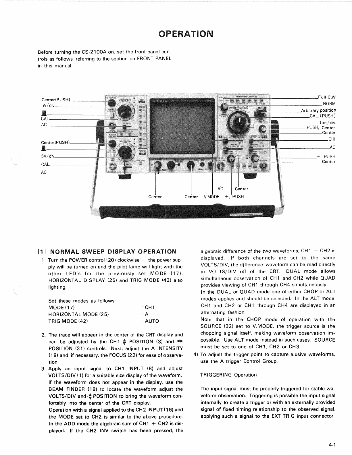
BeforeturningtheCS-2100Aon,setthefrontpanel
con-
trolsasfollows,referringtothesectiononFRONTPANEL
inthismanual.
[1]NORMALSWEEPDISPLAYOPERATION
1.
TurnthePOWERcontrol(20)clockwise— thepowersup-
plywillbeturnedonandthepilotlampwilllightwiththe
otherLED'sforthepreviouslysetMODE(17),
HORIZONTALDISPLAY(25)andTRIGMODE(42)also
lighting.
Setthesemodesasfollows:
MODE07): CH1
HORIZONTALMODE(25): A
TRIGMODE(42): AUTO
2.
ThetracewillappearinthecenteroftheCRTdisplayand
canbeadjustedbytheCH
1
^ POSITION(3)and<>
POSITION(31)controls.Next,adjusttheA INTENSITY
(19)and,ifnecessary,theFOCUS(22)foreaseofobserva-
tion.
3.ApplyaninputsignaltoCH1INPUT(8)andadjust
VOLTS/DIV(1)fora suitablesizedisplayofthewaveform.
Ifthewaveformdoesnotappearinthedisplay,usethe
BEAMFINDER(18)tolocatethewaveformadjustthe
VOLTS/DIVand$ POSITIONtobringthewaveformcon-
fortablyintothecenteroftheCRTdisplay.
Operationwitha signalappliedtotheCH2INPUT(16)and
theMODEsettoCH2issimilartotheaboveprocedure.
IntheADDmodethealgebraicsumofCH1+ CH2isdis-
played.
IftheCH2INVswitchhasbeenpressed,the
algebraicdifferenceofthetwowaveforms,CH1— CH2is
displayed.
Ifbothchannelsaresettothesame
VOLTS/DIV,thedifferencewaveformcanbereaddirectly
inVOLTS/DIVoffoftheCRT.DUALmodeallows
simultaneousobservationofCH1andCH2whileQUAD
providesviewingofCH1throughCH4simultaneously.
IntheDUALorQUADmodeoneofeitherCHOPorALT
modesappliesandshouldbeselected.IntheALTmode,
CH1andCH2orCH1throughCH4aredisplayedinan
alternatingfashion.
NotethatintheCHOPmodeofoperationwiththe
SOURCE(32)settoV.MODE,thetriggersourceisthe
choppingsignalitself,makingwaveformobservationim-
possible.UseALTmodeinsteadinsuchcases.SOURCE
mustbesettooneofCH1,CH2orCH3.
4)Toadjustthetriggerpointtocaptureelusivewaveforms,
usetheA triggerControlGroup.
TRIGGERINGOperation
Theinputsignalmustbeproperlytriggeredforstablewa-
veformobservation.Triggeringispossibletheinputsignal
internallytocreatea triggerorwithanexternallyprovided
signaloffixedtimingrelationshiptotheobservedsignal,
applyingsucha signaltotheEXTTRIGinputconnector.
4-1
OPERATION
ATrigger
1)TheSOURCEcontrolselectsthesignaltobeused.
WiththeV.MODEthesourceisdeterminedbythe
settingoftheVerticalMODE.
Asmentionnedabove,ifCHOPhasbeenselected,
thetriggersourceisthechoppingsignalitself,mak-
ingwaveformobservationimpossible.UseALT
insteadinthiscase.IfSOURCEissettoCH1or
CH2,
regardlessofthesettingofMODE,CH
1
or
CH2signalprovidesthetriggersource.
IfSOURCEissettoEXT(CH3)1/1.or1/10,ex-
ceptforQUADoperation,thesignalappliedtothe
CH3orA EXTTRIGinput(36)isthetrigger
source.ForQUADoperationthisinputistakenas
theCH3signalandcanbeobservedasthetrigger
waveform.
2)AftersettingSOURCE,adjusttheLEVEL/SLOPE
(34)controltosetthetriggerpoint.Syncisindica-
tedbythegreenLEDlighting.
Asnecessarytoobtaina stablesynchronizedsignal
display,adjustHOLDOFF(30)andCOUPLING
(33).
IftheSLOPEcontrolispulledout,thetriggerlevel
isputintotheFIXmodewiththetriggerpointat
thecenterofthewaveform.
5.AdjusttheA SWEEPTIME/DIV(26)controlforanappro-
priatedisplayofthesignalinput.Ifrequired,usetheA
VAR(27)controlas
well.
ThiscompletestheadjustmentprocedurefornormalA
Sweepdisplayoperation.
[2]MAGNIFIEDSWEEPOPERATION
Sincemerelyshorteningthesweeptimetomagnifya portionof
anobservedwaveformcanresultinthedesiredportiondisap-
pearingoffthescreen,suchmagnifieddisplayshouldbeperfor-
medusingtheMAGNIFIEDSWEEP.
Procedure:
UsingthePOSITIONcontrol,adjustthedesiredportionof
waveformtothecenteroftheCRT.PullouttheFINEPULL
X10MAG(31)controltomagnifythedisplay10times.For
thistypeofdisplaythesweeptimeistheSWEEPTIME/DIV
settingdividedby10.
[3]DELAYEDSWEEPOPERATION
DelayedsweepoperationisachievedbyuseofboththeA
SweepandtheB Sweep.
Procedure:
1.
FirstsettheHORIZONTALDISPLAYtoA andadjustthe
CS-2100Afora normalwaveformdisplay.
2.
PullouttheSLOPEPULLSTARTSAFTERDELAY(39)
controltosetthesweepintheSTARTSAFTERDELAY
mode.
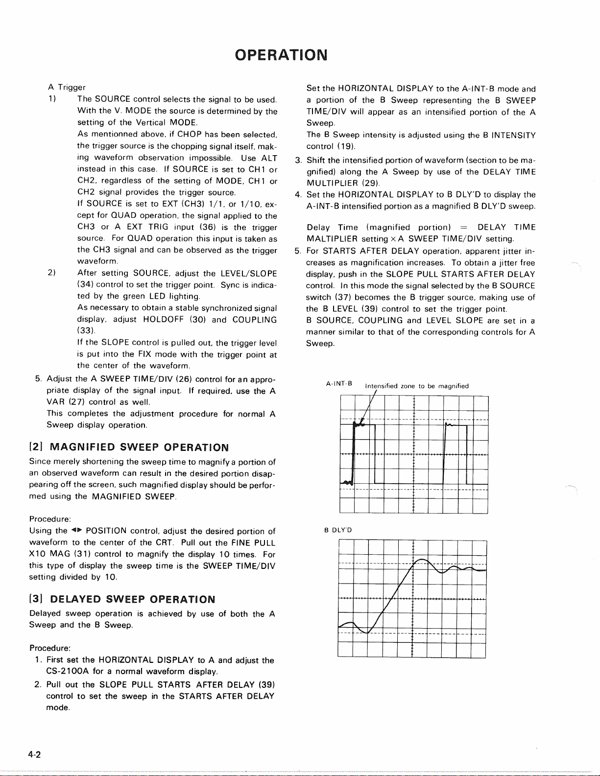
SettheHORIZONTALDISPLAYtotheA-INT-Bmodeand
aportionoftheB SweeprepresentingtheB SWEEP
TIME/DIVwillappearasanintensifiedportionoftheA
Sweep.
TheB SweepintensityisadjustedusingtheB INTENSITY
control(19).
3.Shifttheintensifiedportionofwaveform(sectiontobema-
gnified)alongtheA SweepbyuseoftheDELAYTIME
MULTIPLIER(29).
4.
SettheHORIZONTALDISPLAYtoB DLY'Dtodisplaythe
A-INT-Bintensifiedportionasa magnifiedB DLY'Dsweep.
DelayTime(magnifiedportion)= DELAYTIME
MALTIPLIERsettingx A SWEEPTIME/DIVsetting.
5.ForSTARTSAFTERDELAYoperation,apparentjitterin-
creasesasmagnificationincreases.Toobtaina jitterfree
display,pushintheSLOPEPULLSTARTSAFTERDELAY
control.
InthismodethesignalselectedbytheB SOURCE
switch(37)becomestheB triggersource,makinguseof
theB LEVEL(39)controltosetthetriggerpoint.
BSOURCE.COUPLINGandLEVELSLOPEaresetina
mannersimilartothatofthecorrespondingcontrolsforA
Sweep.
Intensifiedzonetobemagnified
BDLY'D
4-2
A-INT-B
OPERATION
NotethatforthistypeofoperationboththeDELAYTIME
MULTIPLIERandTRIGLEVELaffectthestartofthesweep
sothatthedelaytimeisusedasa referencepoint.
14]ALTERNATINGSWEEPOPERATION
ASweepandB Sweepareusableinanalternatingfashionma-
kingitpossibletoobserveboththenormalandmagnifiedwa-
veformsimultaneously.
Procedure:
1.
SettheHORIZONTALDISPLAYtoA andadjusttheCS-
2100Afora normalwaveformdisplay.
2.
PullouttheSLOPEPULLSTARTSAFTERDELAYcontrol
andsettheHORIZONTALDISPLAYtoALT.Adjust
TRACESEP(30)foreasyobservationofboththeA andB
traces.
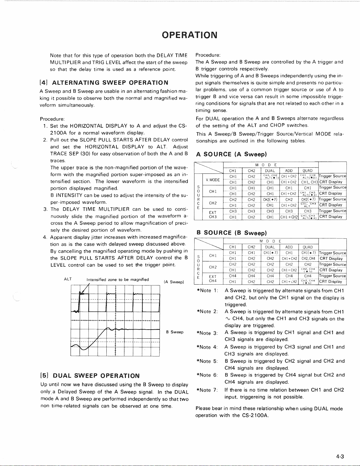
Theuppertraceisthenon-magnifiedportionofthewave-
formwiththemagnifiedportionsuper-imposedasanin-
tensifiedsection.Thelowerwaveformistheintensified
portiondisplayedmagnified.
BINTENSITYcanbeusedtoadjusttheintensityofthesu-
per-imposedwaveform.
3.TheDELAYTIMEMULTIPLIERcanbeusedtoconti-
nuouslyslidethemagnifiedportionofthewaveforma-
crosstheA Sweepperiodtoallowmagnificationofpreci-
selythedesiredportionofwaveform.
4.
Apparentdisplayjitterincreaseswithincreasedmagnifica-
tionasisthecasewithdelayedsweepdiscussedabove.
Bycancellingthemagnifiedoperatingmodebypushingin
theSLOPEPULLSTARTSAFTERDELAYcontroltheB
LEVELcontrolcanbeusedtosetthetriggerpoint.
BSweep
15]
DUALSWEEPOPERATION
UpuntilnowwehavediscussedusingtheB Sweeptodisplay
onlya DelayedSweepoftheA Sweepsignal.IntheDUAL
modeA andB Sweepareperformedindependentlysothattwo
nontime-relatedsignalscanbeobservedatonetime.
Procedure:
TheA SweepandB SweeparecontrolledbytheA triggerand
Btriggercontrolsrespectively.
WhiletriggeringofA andB Sweepsindependentlyusingthein-
putsignalsthemselvesisquitesimpleandpresentsnoparticu-
larproblems,useofa commontriggersourceoruseofA to
triggerB andviceversacanresultinsomeimpossibletrigge-
ringconditionsforsignalsthatarenotrelatedtoeachotherina
timingsense.
ForDUALoperationtheA andB Sweepsalternateregardless
ofthesettingoftheALTandCHOPswitches.
ThisA Sweep/BSweep/TriggerSource/VerticalMODErela-
tionshipsareoutlinedinthefollowingtables.
ASOURCE(ASweep)
•Note1:A SweepistriggeredbyalternatesignalsfromCH1
andCH2,butonlytheCH1signalonthedisplayis
triggered.
*Note2:A SweepistriggeredbyalternatesignalsfromCH1
CH4,
butonlytheCH
1
andCH3signalsonthe
displayaretriggered.
*Note3:A SweepistriggeredbyCH1signalandCH1and
CH3signalsaredisplayed.
*Note4:A SweepistriggeredbyCH3signalandCH1and
CH3signalsaredisplayed.
•Note5:B SweepistriggeredbyCH2signalandCH2and
CH4signalsaredisplayed.
•Note6:B SweepistriggeredbyCH4signalbutCH2and
CH4signalsaredisplayed.
•Note7:IfthereisnotimerelationbetweenCH1andCH2
input,triggereingisnotpossible.
PleasebearinmindtheserelationshipwhenusingDUALmode
operationwiththeCS-2100A.
4-3
BSOURCE(BSweep)
M ODE
CHI CH2 DUAL ADD QUAD
V.MODE CHI CH2
CH1.
CH2
ALT{ * 1 ) CH1+CH2 CHICH4
ALT(*(2) TriggerSource
V.MODE CHI CH2 CHI CH1+CH2
CHI,
CH3
CRTDisplay
s
0
u CHI CHI CHI CHI CHI CHI TriggerSource
s
0
u CHI CHI CH2 CHI CH1+CH2 CHIC H 3
ALT( * 3) CRTDisplay
R CH2 CH2 CH2 CH2(*7) CH2 CH2(*7) TriggerSource
C
E CH2 CHI CH2 CHI CH1+CH2
CHI.
CH3
ALT CRTDisplay
EXT CH3 CH3 CH3 CH3 CH3 TriggerSource
CH3 CHI CH2 CHI CH1+CH2
CHI,
CH3
ALT
(
* 4) CRTDisplay
MODE
CHI CH2 DUAL ADD QUAD
CHI CHI CHI
CH1(*
7) CHI CH1(*7) TriggerSource
S
0
u
CHI CHI CH2 CH2 CH1+CH2 CH2.CH4 CRTDisplay
S
0
u CH2 CH2 CH2 CH2 CH2 CH2 TriggerSource
R
C
E
CH2 CHI CH2 CH2 CH1+CH2
CH2.
CH4
(
* ">) CRTDisplay
R
C
E EXT CH4 CH4 CH4 CH4 CH4 TriggerSource
CH4 CHI CH2 CH2 CH1+CH2
CH2.
CH4
(# 6) CRTDisplay
Intensifiedzonetobemagnified (ASweep)
ALT

OPERATION
r-CAUTION:
ForDUALoperationbesuretosettheTRIGMODEcontrolto
AUTOtoallowsweepofbothA andB tobeperformed.
WhenA andB Sweepsaretobeusedalternately,theCS-
2100Amustbesetuptoprovidebothsweeps.
[6]X-YOPERATION
PhasedifferencemeasurementsmaybemadewiththeCS-
2100AbyuseoftheX-Ydisplaymode.
Procedure:
SettheHORIZONTALDISPLAYcontroltotheX-Ymode.In
thismodetheCH
1
inputbecomestheY-axisinputandtheCH2
inputtheX-axisinputforX-Ydisplay.
ForX-YoperationtheX andY positionsareadjustedusingthe
CH2* POSITIONX-YandCH1* POSITIONcontrolsre-
spectively.
XandY sensitivityissetbyusingtheCH2andCH
1
VARIABLE,
VOLTS/DIVcontrolsrespectively.
BypullingoutthetwoabovementionedPOSITIONcontrols,
thesensitivityofboththeX andY axisismagnifiedby5 times.
TheA INTENSITYcontrolisusedtoadjusttheintensityofthe
displayduringX-Yoperation.
[7]SINGLESWEEPOPERATION
Thismodeofdisplayisusefulforlookingatnon-synchronousor
onetimeevents.
Procedure:
1.
SettheTRIGMODEtoeitherAUTOorNORM,andthe
SLOPEPULLFIXtopushedinposition.
Applya signalofapproximatelythesameamplitudeand
frequencyasthesignalthatistobeobservedtotheCS-
2100Aasthetriggersignalandsetthetriggerlevel.
2.
SetTRIGMODEtoSINGLEandpresstheRESETbutton
—observethatthegreenLEDlightstoindicatethereset
condition.
ThisLEDgoesoutwhentheA Sweepperiodis
completed.
3.Aftertheaboveset-upiscompletedtheCS-2100Ais
readytooperateintheSINGLEsweepmodeofoperation
afterresettingtheinstrumentusingtheRESETbutton.In-
putofthetriggersignalresultsinoneandonlyonesweep.
r-CAUTION:
WiththeHORIZONTALDISPLAYsettoALTorDUAL,the
simultaneousobservationoftheA SweepandB Sweep
waveformsatSINGLESWEEPmodeisnotpossible.Also
forDUALorQUADoperationsimultaneousobservationis
notpossibleusingALTmode.SettheunittotheCHOP
modeinthiscase,
[8]DUALANDQUADTRACEOPERATION
BysettingtheMODEtoDUALorQUAD.DualandQuadtrace
operationcanbeachieved.Whennecessary,setting
HORIZONTALDISPLAYtoALTcaninadditionturnthe
CS-2100Aintoan8-traceinstrument.
Operationofthevariouscontrolsisforthistypeofdisplaymode
similartotheoperatondescribedabove.
[9]CASCADEDOPERATION
Thismodeofoperationisusedwhensensitivitygreaterthan1
mV/divisrequired.
Procedure:
1.
ConnecttheCH1outputtotheCH2inputusinga BNC
cable.
2ForcascadeoperationdepresstheCH
1
andCH2x 5 GAIN
switches.
3.PushtheCH250S2switchandsetV MODEtoCH2.
4.
SettheCH
1
andCH2VOLTS/DIVto5 mVandinputa
sig-
nalfora sensitivityof500^V/divonCH1.
4-4

APPLICATION
ADJUSTMENTS
REQUIRED
BEFORE
STARTING
MEASUREMENTS
PROBE
COMPENSATION
Ifaccuratemeasurementsaretobemade,theeffectofthe
probebeingusedmustbeproperlyadjustedoutputofthe
measurementsystemusingtheinternalcalibrationsignalor
someothersquarewavesource.
1.
Connecttheprobetothechanneltobeusedandsetthe
variouscontrolsfora normalA sweepdisplay.
2.
AdjusttheSWEEPTIME/DIVcontroldisplayofseveral
cyclesofthesignalfromthecalibrationoutput,CAL,
terminal.
3.Adjusttheprobecompensationcontrolfora proper
waveformdisplay.
4.
Theotherchannelsarecompensatedforinthesame
way.NotethatforCH3andCH4thesensitivityis
0.1V/DIV(1/1)sothatwhenusinga 10:1probe
sufficientwaveformamplitudeisnotavailable,sothat
analternatesquarewavesignalgeneratormustbeused
forthecompensatingprocedure.
Correct
compensation
Over
compensation
Insufficient
compensation
TRACE
ROTATIONCOMPENSATION
Rotationfroma horizontaltracepositioncanbethecauseof
measurementerrors.
AdjusttheCS-2100Acontrolsfora normaldisplay.Setthe
AC-GND-DCswitchtoGNDandTRIGMODEtoAUTO.
Adjustthe* POSITIONcontrolsuchthatthetraceisoverthe
centerhorizontalgraduationline.
Ifthetraceappearstoberotatedfromhorizontal,alignit
withthecentergraduationlineusingtheTRACEROTATION
controllocatedonthebottomoftheinstrument.
MEASUREMENTS
DC
VOLTAGEMEASUREMENTS
Thisproceduredescribesthemeasurementprocedurefor
DCwaveforms.
Procedure:
1.
ConnectthesignaltobemeasuredtotheINPUT
con-
nectorandsettheV MODEtothechanneltobeused.
SettheVOLTS/DIVandSWEEPTIME/DIVswitchto
obtaina normaldisplayofthewaveformtobe
measured.
SettheVARIABLEcontroltotheCAL
position.
2.
SetTRIGMODEtoAUTOandAC-GND-DCtotheGND
positiontodeterminethetruegroundlevel.Usingthe
T
POSITIONcontroladjustthetracepositiontothe
referencelevelposition,makingsurenottodisturbthis
settingoncemade.
3.SettheAC-GND-DCswitchtotheDCpositionto
observetheinputwaveform,includingitsDCcompo-
nent.IfanappropriatereferencelevelorVOLTS/DIV
settingwasnotmade,thewaveformmaynotbevisible
ontheCRTscreenatthispoint.Ifso,press
BEAMFINDERtolocateitandresetVOLTS/DIV
and/orthe| POSITIONcontrol.
4.
Usethe« • POSITIONcontroltobringtheportionofthe
waveformtobemeasuredtothecentervertical
graduationlineoftheCRTscreen.
5.Measuretheverticaldistancefromthereferencelevel
tothepointtobemeasured,(thereferencelevelcanbe
checkedbysettingtheAC-GND-DCswitchagainto
GND).
Multiplythedistancemeasuredabovebythe
VOLTS/DIVsettingandistheprobeusedisnota 1:1
probe,
bytheprobeattenuationratioas
well.
If" x 5
GAIN"hasbeensetmultiplythevalueby1/5as
well.
Voltagesaboveandbelowthereferencelevelare
positiveandnegativevaluesrespectively.
Usingtheformula:
DClevel= Verticaldistanceindivisionsx (VOLTS/DIV
setting)x (probeattenuationratio)x " x 5 GAIN"value1
(1/5)
Measuringpointadjustedtothe
centerverticalscale
by<>
POSITION
5-1
Groundpotentialadjustedby
y
position(referenceline)
[EXAMPLE]
Fortheexample,thepointbeingmeasuredis3.8divisions
fromthereferencelevel(groundpotential).
IftheVOLTS/DIVwassetto0.2Vanda 10:1probewas
used.
Substitutingthegivenvalues-
DClevel= 3.8(div)x 0.2(V)x 10= 7.6V
APPLICATION
MEASUREMENT
OFTHE
VOLTAGE
BETWEEN
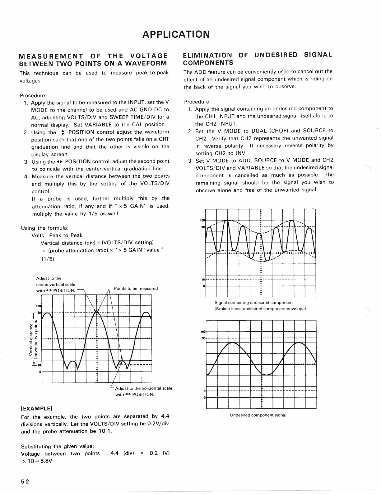
TWOPOINTSONA WAVEFORM
Thistechnique
canbe
used
to
measurepeak-to-peak
voltages.
Procedure:
1.
Apply
the
signal
tobe
measured
tothe
INPUT,
settheV
MODE
tothe
channel
tobe
used
and
AC-GND-DC
to
AC,
adjustingVOLTS/DIV
and
SWEEPTIME/DIV
fora
normaldisplay.
Set
VARIABLE
totheCAL
position.
2.
Using
the*
POSITIONcontroladjust
the
waveform
positionsuchthat
oneofthetwo
pointsfalls
ona CRT
graduationline
and
that
the
other
is
visible
onthe
displayscreen.
3.Using
the<>
POSITIONcontrol,adjust
the
secondpoint
tocoincidewith
the
centerverticalgraduationline.
4.
Measure
the
verticaldistancebetween
thetwo
points
andmultiplythis
bythe
setting
ofthe
VOLTS/DIV
control.
If
a
probe
is
used,furthermultiplythis
bythe
attenuationratio,
ifanyandif" x 5
GAIN"
is
used,
multiply
the
value
by1/5as
well.
Using
the
formula:
VoltsPeak-to-Peak
=Verticaldistance
(div)x
(VOLTS/DIVsetting)
x(probeattenuationratio)
x " x 5
GAIN"value
1
(1/5)
Adjust
tothe
centerverticalscale
withPOSITION.
-
Points
tobe
measured
IEXAMPLE]
For
the
example,
thetwo
points
are
separated
by4.4
divisionsvertically.
Letthe
VOLTS/DIVsetting
be
0.2V/div
and
the
probeattenuation
be10:1.
Substituting
the
givenvalue:
Voltagebetween
two
points
=4.4(div)x 0.2(V)
x10=
8.8V
ELIMINATION
OF
UNDESIREDSIGNAL
COMPONENTS
The
ADD
feature
canbe
convenientlyused
to
cancel
outthe
effect
ofan
undesiredsignalcomponentwhich
is
riding
on
theback
ofthe
signal
you
wish
to
observe.
Procedure:
1.
Apply
the
signalcontaining
an
undesiredcomponent
to
the
CH1
INPUT
andthe
undesiredsignalitselfalone
to
the
CH2
INPUT.
2.
SettheV
MODE
to
DUAL(CHOP)
and
SOURCE
to
CH2.
Verifythat
CH2
represents
the
unwantedsignal
inreversepolarity.
If
necessaryreversepolarity
by
setting
CH2toINV.
3.
SetV
MODE
toADD,
SOURCE
toV
MODE
andCH2
VOLTS/DIV
and
VARIABLE
so
that
the
undesiredsignal
component
is
cancelled
as
much
as
possible.
The
remainingsignalshould
bethe
signal
you
wish
to
observealone
and
free
ofthe
unwantedsignal.
Signalcontainingundesiredcomponent
(Brokenlines:undesiredcomponentenvelope)
Undesiredcomponentsignal
5-2
Verticaldistance
between
two
points
Adjust
tothe
horizontalscale
withPOSITION.

APPLICATION
Signalwithoutundesiredcomponent
TIME
MEASUREMENTS
This
isthe
procedure
for
makingtimemeasurements
between
two
points
ona
waveform.
The
combination
ofthe
SWEEPTIME/DIV
andthe
horizontaldistance
in
divisions
between
thetwo
points
is
used
inthe
calculation.
Procedure:
1.
Apply
the
signal
tobe
measured
tothe
INPUT
con-
nector
andsettheV
MODE
tothe
channel
tobe
used.
AdjustVOLTS/DIV
and
SWEEPTIME/DIV
fora
normal
display.
Besurethat
the
VARIABLEcontrol
issettoCAL
2.
Using
the£
POSITIONcontrol
setoneofthe
points
to
beused
asa
reference
to
coincidewith
the
horizontal
centeHine.
Use
the«•
POSITIONcontrol
toset
thispoint
atthe
intersection
ofany
verticalgraduationline.
3.Measure
the
horizontaldistancebetween
thetwo
point^.
Multiplythis
bythe
setting
oftheA
SWEEPTIME/DIV
control
to
obtain
the
timebetween
thetwo
points.
If
horizontal
" x 10MAG"is
used,multiplythisfurther
by
1/10.
Using
the
formula:
Time
=
Horizontaldistance
(div)x
(SWEEPTIME/DIV
setting)
x " x 10MAG"
value
1
(1/10)
[EXAMPL^]
For
the
example,
the
horizontaldistancebetween
thetwo
points
is5.4
divisions.
If
the
SWEEPTIME/DIV
is
0.2ms/div
we
calculate.
Adjust
to
thevertical—j-
scalewith•*
•
POSITION
Adjust
to
horizontal
centerlinewith
POSITION
Horizontaldistance
Substituting
the
givenvalue:
Time
= 5.4(div)x 0.2(ms)=
1.08ms
FREQUENCY
MEASUREMENTS
Frequencymeasurements
are
made
by
measuring
the
period
of
one
cycle
of
waveform
and
taking
the
reciprocal
of
this
timevalue
asthe
frequency.
Procedure:
1.
Setthe
oscilloscope
upto
display
one
cycle
of
waveform
(one
period).
2.
The
frequency
isthe
reciprocal
ofthe
periodmeasured.
Using
the
formula:
^req
—
period
1
cycle=40jus(5/is/div.x8div.)
[EXAMPLE]
Aperiod
of40fis is
observed
and
measured.
Substituting
the
givenvalue:
Freq
=
1/[40x
106]= 2.5x104= 25kHz
5-3
Table of contents
Other Trio Test Equipment manuals


