Trio CS-1060 User manual
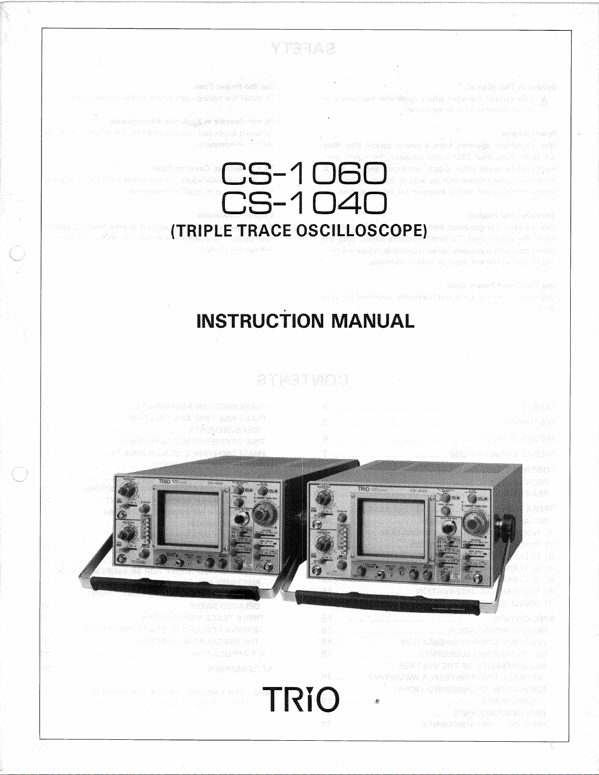
CS-1OBO
CS-1040
(TRIPLETRACEOSCILLOSCOPE)
INSTRUCTIONMANUAL
TRIO

SAFETY
SymbolinThisManual
^Thissymbolindicateswhereapplicablecautionaryor
otherinformationistobefound.
PowerSource
Thisequipmentoperatesfroma powersourcethatdoes
notapplymorethan250V rmsbetweenthesupply
con-
ductorsorbetweeneithersupplyconductorandground.A
protectivegroundconnectionbywayofthegrounding
con-
ductorinthepowercordisessentialforsafeoperation.
GroundingtheProduct
Thisequipmentisgroundedthroughthegroundingconduc-
torofthepower
cord.
Toavoidelectricalshock,plugthe
powercordintoa properlywiredreceptaclebeforeconnec-
tingtotheequipmentinputoroutputterminals.
UsetheProperPowerCord
Useonlythepowercordandconnectorspecifiedforyour
product.
UsetheProperFuse
Toavoidfirehazard,usea fuseofthecorrecttype.
DonotOperateinExplosiveAtmospheres
Toavoidexplosion,donotoperatethisproductinanex-
plosiveatmosphere.
DonotRemoveCoverorPanel
Toavoidpersonalinjury,donotremovethecoverorpanel.
Referservicingtoqualifiedpersonnel.
VoltageConversion
Ifthepowersourceisnotappliedtoyourproduct,contact
yourdealer.Toavoidelectricalshock,donotperformthe
voltageconversion.
SAFETY2
FEATURES3
SPECIFICATIONS4
PREPARATIONFORUSE7
CONTROLSANDINDICATORS9
FRONTPANEL9
REARPANEL13
OPERATION14
INITIALSTARTINGPROCEDURE14
(1)NORMALSWEEPDISPLAYOPERATION14
(2)MAGNIFIEDSWEEPOPERATION17
(3>DELAYEDSWEEPOPERATION17
(4)ALTERNATINGSWEEPOPERATION17
(5)X-YOPERATION18
(6)VIDEOSIGNALOBSERVATION18
(7)SINGLESWEEPOPERATION18
APPLICATION19
PROBECOMPENSATION19
TRACEROTATIONCOMPENSATION19
DCVOLTAGEMEASUREMENTS19
MEASUREMENTSOFTHEVOLTAGE
BETWEENTWOPOINTSONA WAVEFORM20
ELIMINATIONOFUNDESIREDSIGNAL
COMPONENTS20
TIMEMEASUREMENTS21
FREQUENCYMEASUREMENTS21
PULSEWIDTHMEASUREMENTS22
PULSERISETIMEANDFALLTIME
MEASUREMENTS22
TIMEDIFFERENCEMEASUREMENTS23
PHASEDIFFERENCEMEASUREMENTS24
RELATIVEMEASUREMENTS24
PULSEJITTERMEASUREMENT26
SWEEPMULTIPLICATION(MAGNIFICATION)26
DELAYEDSWEEPTIMEMEASUREMENT27
PULSEWIDTHMEASUREMENTSUSING
DELAYEDSWEEP27
FREQUENCYMEASUREMENTSUSING
DELAYEDSWEEP28
PULSEREPETITIONTIME29
USINGDELAYEDSWEEPFORMEASUREMENTSOF
RISETIMESANDFALLTIMES29
TIMEDIFFERENCEMEASUREMENTSUSING
DELAYEDSWEEP29
TRIPLE-TRACEAPPUCATIONS30
OBSERVATIONOFTHESTARTPORTIONOF
THEIRREGULARWAVEFORM30
X-YAPPLICATION31
ACCESSORIES32
Note:Thisinstructionmanualisdescribedfortwomodels.
Refertoitemappliedtoyourproduct.
2
FEATURES
1.
Verticalaxishashighsensitivityandwidebandwidth
andespeciallycoversfullyspecifiedfrequency
responseat5mV/divforallmodels.
CS-1060;
1mV/div,2mV/div: DCto20MHz,-3dB
5mV/div: DCto60MHz,-3dB
CS-1040;
1mV,2mV/div: DCto
1
5 MHz,-3dB
5mV/div: DCto40MHz,-3dB
2.
Verticalsensitivityrangeisselectablefrom1mV/divto
5V/divwithrotaryswitchcontinuously.
3.Timebasepermitsthehighsweepspeed.
CS-1060;5nsec/div(x10MAG)
CS-1040;10nsec/div(x10MAG)
4.
Verticalsensitivityerrorandsweeprateerrorare
±3%
andaccuratemeasurementsareprovided.
5.The150mmrectangular,domedmeshtypeCRTwith
internalgraticuleprovideshighbrightnessandac-
curatemeasurements,freeofparallaxerror.
CS-1060;accelerationvoltage;16kV.
CS-1040;accelerationvoltage;12kV.
6.Forconvenienceinmakingrisetimemeasurements,
the0%,10%,90%and100%levelsaremarkedon
thegraticulescaleoftheCRT.
7.Thebuilt-inAuto-focuscircuitkeepsthewaveformsin
clearfocusautomaticallyregardlessoftheINTENSITY
controlsetting.
8.Tracerotationiselectricallyadjustablefromthefront
panel.
9.BySCALEILLUMcontrol,thewaveformiseasy
observedindarkenedareaandthephotographofthe
waveformiseasyprovideda singlephotographofthe
waveformsuperimposedonthegraticulescale.
10.
Delaysweepmodesareavailableinnotonly
Con-
tinuousDelay(STARTSAFTERDELAY)andtrigger
Delay(TRIG)butalsobothA andB zeroDelay(DELAY
TIMEZERO)allowingtoobservethewholeextentof
anycomplicatedpulsetrainwithmagnifictionas
necessary.
11.
Singlesweeppermitsviewingandphotographingone-
timeevents.
12.
TRIPLEmodepresentsa triple-traceoscilloscope;even
sixtracesofwaveformsmaybeobservedsimultane-
ouslywithHORIZDISPLAYsetatALT.
13.
Thedelaylinepermitsviewingofleadingedgeofhigh-
frequency,fastrisetimepulses.
14.
SelectableAUTOFREERUNfunctionprovidessweep
withouttriggerinputsignal.
15.
TheFRAME-LINEswitchprovidesselectionofsync
pulseforsweeptriggeringfromsmallamplitudeto
largeamplitudewithoutadjustingwhenviewingcom-
positevideowaveforms.
16.
Verticalmodeautomaticallyprovidesthetriggersignal
withTRIGSOURCEandV.MODEswitches.
17.
X-Yoperationiseasyprovidedbyone-touche.
18.
ProvideswithCH1OUTPUTterminaltomonitorinput
signalofCH1.
19.
SWEEPGATEandSWEEPOUTPUTterminalsarepro-
vides.
20.
DELAYTIMEMULTpermitstheaccuratetime
measurementswiththedialscale.
3

SPECIFICATIONS
CS-1060 CS-1040
CRT 150HTM31
Rectangular,withinternalgraticule 150JTM31
Rectangular,withinternalgraticule
AccelerationVoltage 16
kV
12
kV
DisplayArea 8x10
div(1
div=
10mm)
VERTICALAXIS CH1and
CH2
Sensitivity 1mV/divto
5
V/div,
±3%
Attenuator 12steps,
1
mV/div
to5
V/div
in1-2-5
sequence.
Verniercontrol
for
fullyadjustablesensitivitybetweensteps.
InputImpedance 1
MO±2%,
approx
20pF
FrequencyResponse
5mV/div
to
5V/div
DC;
DCto60
MHz,
-3dB
AC;
5 Hzto60
MHz,
-3dB
DC;
DCto40
MHz,
-3dB
AC;
5
Hz,
to40
MHz,
-3dB
1mV/div,
2
mV/div
DC;
DCto20
MHz,
-3dB
AC;
5 Hzto20
MHz,
-3dB
DC;
DCto15
MHz,
-3dB
AC;
5 Hzto15
MHz,
-3dB
RiseTime 5.8nsec
or
less
(60MHz)
17.5nsec
or
less
(20MHz)
8.8nsec
or
less
(40MHz)
23.4nsec
or
less
(15MHz)
SignalDelayTime Approx.20nsec
ontheCRT
screen
Crosstalk
—
40dB
minimum
OperatingModes
CH1;
singletrace
CH2;
singletrace
ADD;
CH1+CH2added
asa
singletrace
DUAL;
CH1and
CH2,dualtrace
TRIPLE;
CH1,
CH2andCH3
tripletrace
ALT;dualtrace
or
tripletrace,alternating
CHOP;
dual
or
tripletrace,chopped
ChopFrequency Approx.
250kHz
ChannelPolarity Normal
or
inverted,channel
2
onlyinverted
A
MaximumInputvoltage 500
Vp-por250V
(DC
+
ACpeak)
Non-DistortedMaximumAmplitude Morethan
8 div(DCto60MHz)
Morethan
8 div(DCto40MHz)
VERTICALAXIS CHS
Sensitivity 0.1V/div
and1
V/div
±3%
InputResistance 1
MQ±2%
InputCapacitance Approx27pF
FrequencyResponse
DC:
DCto60
MHz,
-3dB
DC:
DCto40
MHz,
-3dB
FrequencyResponse
AC:
5 Hzto60
MHz,
-3dB
AC:
5 Hzto40
MHz,
-3dB
RiseTime 5.8nsec
or
less 8.8nsec
or
less
SignalDelayTime Same
as
CH1
andCH2
A
MaximumInputVoltage 50
V
(DC
+
ACpeak)
HORIZONTALAXIS
Inputthru
CH2,
x 10MAGnot
included
OperatingModes WithHORIZDISPLAYswitch,
X-Y
operation
is
selectable
CH1;
Y
axis
CH2;
X
axis
Sensitivity Same
as
verticalaxis
(CH2)
4

CS-1060 CS-1040
InputImpedance Sameasverticalaxis(CH2)
FrequencyResponse
DC;
DCto1 MHz,-3dB
AC;
5 Hzto1 MHz,-3dB
X-YPhaseDifference 3°orlessat100kHz
AMaximumInputVoltage Sameasverticalaxis(CH2)
SWEEP
Type A;A sweep
ALT;
A sweep(intensifiedfordurationofB sweep)andB sweep(delayed
sweep)alternating
INT;
DurationofB sweepisdisplayedasanintensifiedportionofA sweep.
B;Delayedsweep
X-Y;X-Yoscilloscope
SweepTime A 0.05
/is/div
to0.5s/div,±3%in22
ranges,
in1-2-5sequence.
Verniercontrolprovidesfullyadjustable
sweeptimebetweensteps.
0.1
/is/div
to0.5s/div,±3%in21
ranges,
in1-2-5sequence.
Verniercontrolprovidesfullyadjustable
sweeptimebetweensteps.
SweepTime
B 0.05
/ts/div
to50ms/div,±3%in19
ranges,
in
1
-2-5sequence. 0.1
/ts/div
to50ms/div,±3%in18
ranges,
in
1
-2-5sequence.
SweepMagnification x10(tentimes)±5%
Linearity
±3%
allranges,
±5%
on0.05
/is/div
to0.1
/is/div
rangeatx 10MAG.
Holdoff ContinuouslyvariablefromNORMtomorethantentimes(MAX)
TraceSeparation BsweepcanbeseparatedfromA sweepupto4 divisions,continuously
adjustable.
DelayMethod Continuousdelay(STARTSAFTERDELAY),Triggerdelay(TRIG),Zerodelay
(DELAYTIMEZERO)
DelayTime From100nsecto0.5sec.Availabledelaytimeis0.2to10timestheA sweep
timesetting,continuouslyadjustable.
Timedifferencemeasurement
accuracy
±2%
DelayJitter
1/20000
oftentimesofA sweeptimesetting
TRIGGERING
Triggermode
AUTO,
NORM,FIX,SINGLE
Triggersource
V.MODE;
TriggerselectedbyverticalMODEswitch.
CH1;
TriggeredbyCH1signal
CH2;
TriggeredbyCH2signal
CH3/EXT;TriggeredbyCHSsignal
LINE;
Triggeredbylinevoltage
Coupling
AC,
HFrej,DC,VIDEOFRAME,VIDEOLINE
Triggersensitivity FREQ.RANGE INT EXT FREQ.RANGE INT EXT
DC DC-60MHz 1div 0.1Vp-p DC-40MHz 1div 0.1VP-P
AC SameasforDCbutincreasedminimumlevelbelow10Hz
AC,
HFrej Increasedminimumlevelbelow10Hzandabove20kHz
VIDEO
FRAME,
LINE 1div 0.1Vp-p
FRAME,
LINE 1div 0.1Vp-p
AUTO:
Sameasabovespecificationsforabove50Hz.
FIX:Sameasabovespecificationsforabove50Hz.
5
CS-1060 CS-1040
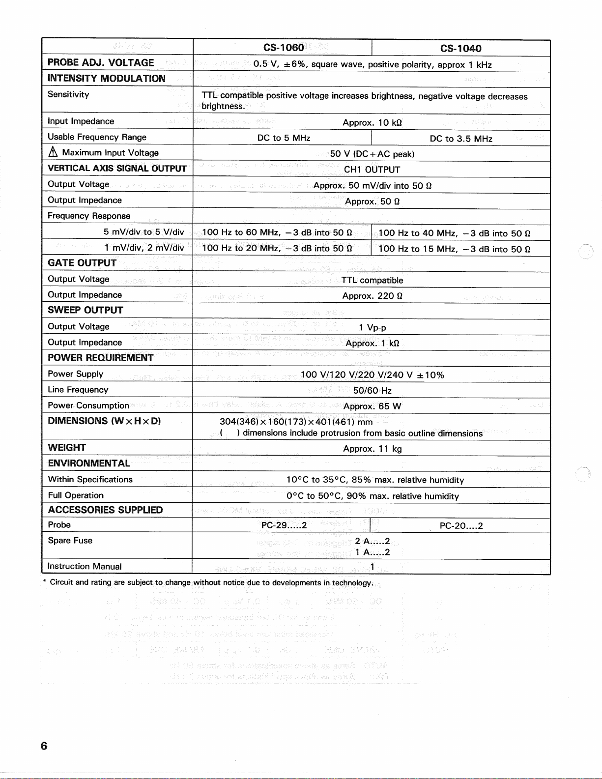
PROBEADJ.VOLTAGE
0.5
V,±6%,
squarewave,positivepolarity,approx
1 kHz
INTENSITYMODULATION
Sensitivity TTLcompatiblepositivevoltageincreasesbrightness,negativevoltagedecreases
brightness.
InputImpedance Approx.
10kQ
UsableFrequencyRange DC
to5 MHz
DC
to3.5MHz
A
MaximumInputVoltage 50
V
(DC
+
ACpeak)
VERTICALAXISSIGNALOUTPUT CH1OUTPUT
OutputVoltage Approx.
50
mV/divinto
50ft
OutputImpedance Approx.
50ft
FrequencyResponse
5mV/div
to5
V/div 100
Hzto60MHz,-3dB
into
50ft
100
Hzto40MHz,-3dB
into
50ft
1mV/div,
2
mV/div 100
Hzto20MHz,-3dB
into
50ft
100
Hzto15MHz,-3dB
into
500
GATEOUTPUT
OutputVoltage TTLcompatible
OutputImpedance Approx.
220ft
SWEEPOUTPUT
OutputVoltage 1
Vp-p
OutputImpedance Approx.
1 kft
POWERREQUIREMENT
PowerSupply 100
V/120
V/220V/240
V ±
10%
LineFrequency 50/60
Hz
PowerConsumption Approx.
65W
DIMENSIONS(WxHxD)
304(346)x160(173)x401(461)
mm
(
)
dimensionsincludeprotrusionfrombasicoutlinedimensions
WEIGHT
Approx.
11kg
ENVIRONMENTAL
WithinSpecifications 10°C
to
35°C,
85%max.
relativehumidity
FullOperation 0°C
to
50°C,
90%max.
relativehumidity
ACCESSORIESSUPPLIED
Probe PC-29.....2 PC-20....2
SpareFuse 2
A 2
1
A 2
InstructionManual 1
*Circuit
and
rating
are
subject
to
changewithoutnotice
dueto
developments
in
technology.
6
PREPARATIONFORUSE
SAFETY
Beforeconnectingtheinstrumenttoa powersource,
carefullyreadthefollowinginformation,thenverifythat
theproperpowercordisusedandtheproperlinefuseisin-
stalledforpowersource.Thespecifiedvoltageisshownat
theleftsideofthepowercordontherearpanel.Ifthe
powercordisnotappliedforspecifiedvoltage,thereis
alwaysa certainamountofdangerfromelectricshock.
Linevoltage
Thisinstrumentoperatesusingac-powerinputvoltages
that100/120/220/240V atfrequenciesfrom50Hzto
60Hz.
Powercord
Thegroundwireofthe3-wireacpowerplugplacesthe
chassisandhousingoftheoscilloscopeatearthground.Do
notattempttodefeatthegroundwireconnectionorfloat
theoscilloscope;todosomayposea greatsafetyhazard.
Theappropriatepowercordissuppliedbyanoptionthatis
specifiedwhentheinstrumentisordered.
TheoptionalpowercordsareshownasfollowsinFig.1.
Linefuse
Thefuseholderislocatedontherearpanelandcontains
thelinefuse.Verifythattheproperfuseisinstalledby
replacingthelinefuse.
5.Alwaysusetheprobegroundclipsforbestresults.Do
notuseanexternalgroundwireinlieuoftheprobe
groundclips,asundesiredsignalsmaybeintroduced.
6.Operationadjacenttoequipmentwhichproducesstrong
acmagneticfieldsshouldbeavoidedwherepossible.
Thisincludessuchdevicesaslargepowersupplies,
transformers,electricmotors,etc.,thatareoftenfound
inanindustrialenvironment.Strongmagneticshields
canexceedthepracticalCRTmagneticshieldinglimits
andresultinterferenceanddistortion.
7.Probecompensationadjustmentmatchestheprobeto
theinputofthescope.Forbestresults,compensation
ofprobeshouldbeadjustedinitially,thenthesamepro-
bealwaysusedwiththeinputofscope.Probecompen-
sationshouldbereadjustedwhenevera probefroma
differentscopeisused.(Seepage19)
8.Push-pushswitchesareusedforx 10MAGandSLOPE
("+ " and"
—");
everypushoftheswitchalternates
themodetotheotheroneassignedtothesameswitch.
LookattheLEDindicatorsforwhichmodesareworking.
9.InX-Yoperation,donotpulloutthePULLx10MAG
switch.
Ifpulledoutit,noisemayappeareonthe
waveform.
EQUIPMENTPROTECTION
1.
Neverallowa smallspotofhighbrilliancetoremainsta-
tionaryonthescreenformorethana fewseconds.The
screenmaybecomepermanentlyburned.A spotwilloc-
curonlywhenthescopeissetupforX-Yoperationand
nosignalisapplied.Eitherreducetheintensitysothe
spotisbarelyvisible,switchbacktonormalsweep
operationwhennosignalisapplied,orsetupthescope
forspotblanking.
2.
Nevercovertheventilatingholesonthetopofthe
oscilloscope,asthiswillincreasetheoperating
temperatureinsidethecase.
3.Neverapplymorethanthemaximumratingtothe
oscilloscopeinputs.
CH1,
CH2INPUTjacks:500Vp-por250V (dc+ ac
peak)
CH3INPUTjack:50V (dc+ acpeak)
ZaxisINPUTjack:50V (dc+ acpeak)
Neverapplyexternalvoltagetotheoscilloscopeoutput
terminals.
4.
Alwaysconnecta cablefromtheearthground(GND)
jackoftheoscilloscopetothechassisoftheequipment
undertest.Withoutthiscaution,theentirecurrentfor
theequipmentundertestmaybedrawnthroughthe
probeclipleadsundercertaincircumstances.Such
con-
ditionscouldalsoposea safetyhazard,whichthe
groundcablewillprevent.
7
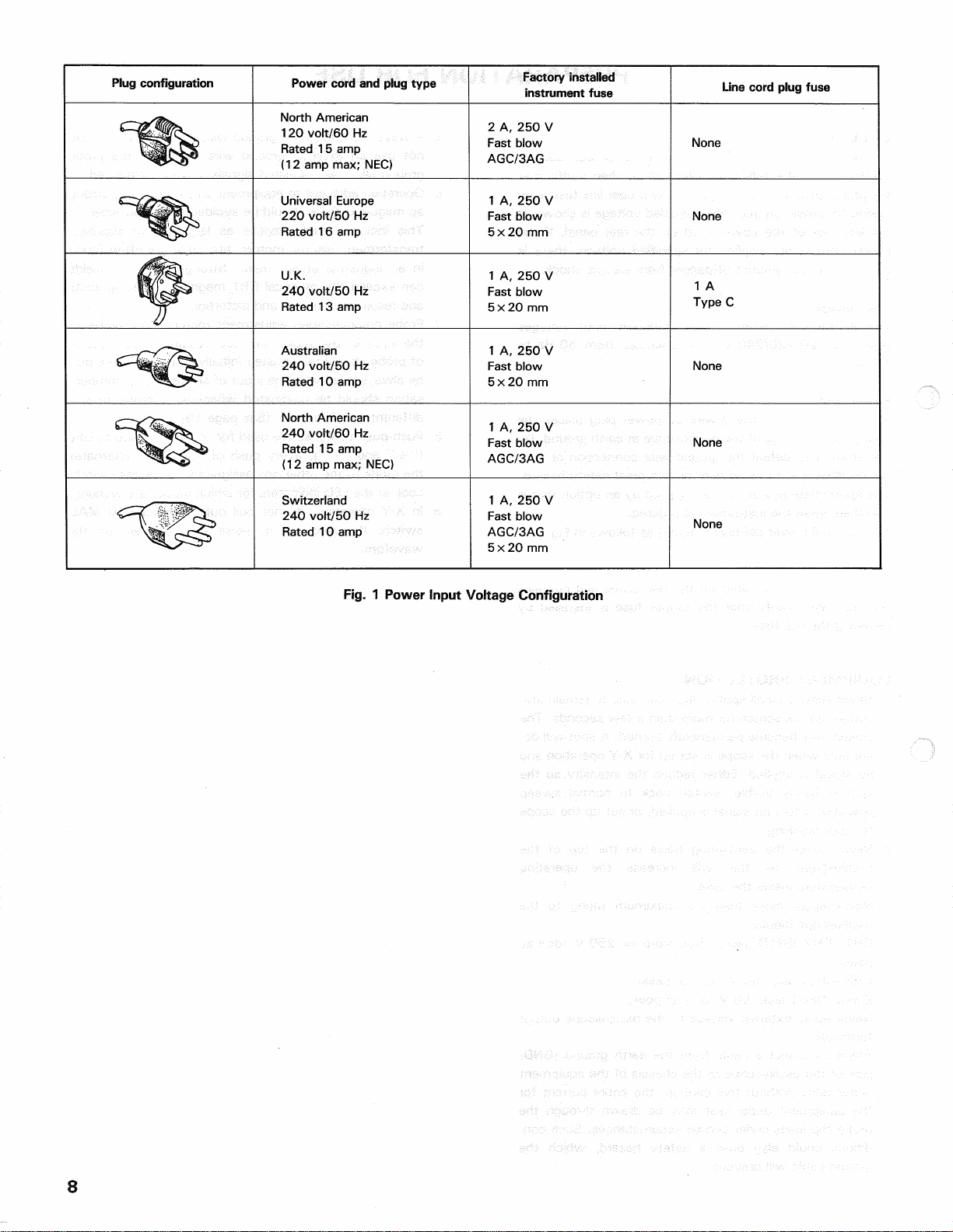
Plugconfiguration Powercordandplugtype Factoryinstalled
instrumentfuse Linecordplugfuse
NorthAmerican
120volt/60Hz
Rated15amp
(12ampmax;NEC)
2A,250V
Fastblow
AGC/3AG None
UniversalEurope
220volt/50Hz
Rated16amp
1A,250V
Fastblow
5x 20mm None
U.K.
240volt/50Hz
Rated13amp
1A,250V
Fastblow
5x 20mm
1A
TypeC
Australian
240volt/50Hz
Rated10amp
1A,250V
Fastblow
5x 20mm None
NorthAmerican
240volt/60Hz
Rated15amp
(12ampmax;NEC)
1A,250V
Fastblow
AGC/3AG None
Switzerland
240volt/50Hz
Rated10amp
1A,250V
Fastblow
AGC/3AG
5x 20mm
None
Fig.
1 PowerInputVoltageConfiguration
8
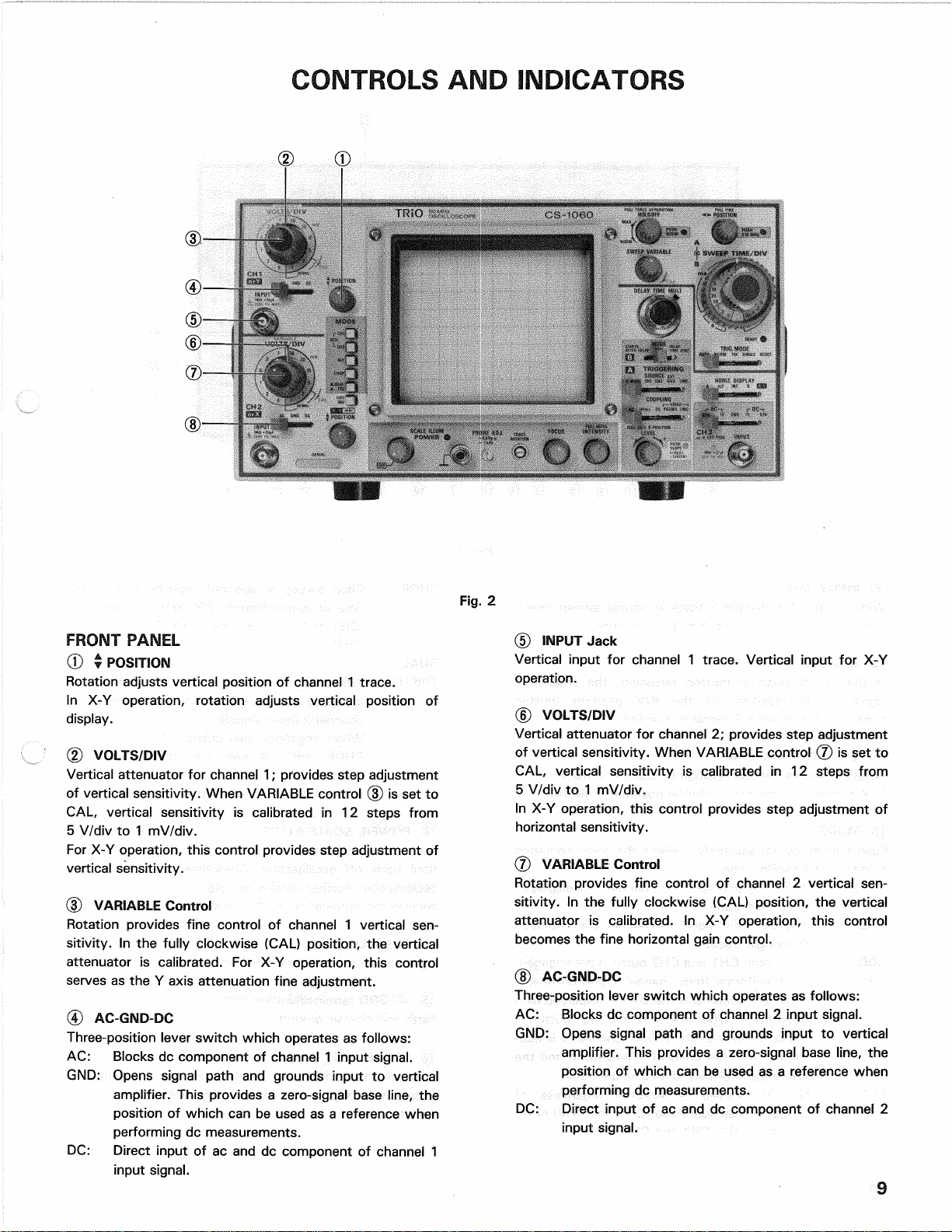
CONTROLSANDINDICATORS
FRONTPANEL
0T POSITION
Rotationadjustsverticalpositionofchannel1 trace.
InX-Yoperation,rotationadjustsverticalpositionof
display.
(2)VOLTS/DIV
Verticalattenuatorforchannel1;providesstepadjustment
ofverticalsensitivity.WhenVARIABLEcontrol(3)issetto
CAL,
verticalsensitivityiscalibratedin12stepsfrom
5V/divto1 mV/div.
ForX-Yoperation,thiscontrolprovidesstepadjustmentof
verticalsensitivity.
(3)VARIABLEControl
Rotationprovidesfinecontrolofchannel1 vertical
sen-
sitivity.Inthefullyclockwise(CAL)position,thevertical
attenuatoriscalibrated.ForX-Yoperation,thiscontrol
servesastheY axisattenuationfineadjustment.
(4)AC-GND-DC
Three-positionleverswitchwhichoperatesasfollows:
AC:
Blocksdccomponentofchannel1 inputsignal.
GND:
Openssignalpathandgroundsinputtovertical
amplifier.Thisprovidesa zero-signalbaseline,the
positionofwhichcanbeusedasa referencewhen
performingdcmeasurements.
DC:
Directinputofacanddccomponentofchannel1
inputsignal.
(5)
INPUTJack
Verticalinputforchannel1 trace.VerticalinputforX-Y
operation.
(6)VOLTS/DSV
Verticalattenuatorforchannel2;providesstepadjustment
ofverticalsensitivity.WhenVARIABLEcontrol(7)issetto
CAL,
verticalsensitivityiscalibratedin12stepsfrom
5V/divto1 mV/div.
InX-Yoperation,thiscontrolprovidesstepadjustmentof
horizontalsensitivity.
(7)VARIABLEControl
Rotationprovidesfinecontrolofchannel2 vertical
sen-
sitivity.Inthefullyclockwise(CAL)position,thevertical
attenuatoriscalibrated.InX-Yoperation,thiscontrol
becomesthefinehorizontalgaincontrol.
(8)AC-GND-DC
Three-positionleverswitchwhichoperatesasfollows:
AC:
Blocksdccomponentofchannel2 inputsignal.
GND:
Openssignalpathandgroundsinputtovertical
amplifier.Thisprovidesa zero-signalbaseline,the
positionofwhichcanbeusedasa referencewhen
performingdcmeasurements.
DC:
Directinputofacanddccomponentofchannel2
inputsignal.
Fig.
2

Fig.
3
(DINPUTJack
Verticalinputforchannel2 traceinnormalsweepopera-
tion.
ExternalhorizontalinputinX-Yoperation.
©CH2INV
IntheNORMposition(buttonreleased),thechannel2
signalisnon-inverted.IntheINVposition(button
engaged),thechannel2 signalisinverted.
(0)• POSITION,X-Y
Rotationadjustsverticalpositionofchannel2 trace.
InX-Yoperationadjustshorizontalpositionofdisplay.
@MODE
Pushbuttonswitchassembly;selectsthebasicoperating
modesoftheoscilloscope.
CH1:
Onlytheinputsignaltochannel1 isdisplayed
asa singletrace.
CH2:
Onlytheinputsignaltochannel2 isdisplayed
asa singletrace.
ADD:
WhenbothCH1andCH2buttonsareengaged,
(CH1+CH2)thewaveformsfromchannel1 andchannel2
inputsareaddedandthesumisdisplayedasa
singletrace.WhentheCH2INV@ buttonis
engaged,
thewaveformfromchannel2 issub-
tractedfromthechannel1 waveformandthe
differenceisdisplayedasa singletrace.
ALT:Alternatesweepisselectedregardlessof
sweeptimeasdualtrace(CH1andCH2)or
tri-
pletrace(CH1,CH2andCH3)
CHOP:
Chopsweepisselectedregardlessofsweep
timeatapproximately250kHzasdualtrace
(CH1andCH2)ortripletrace(CH1,CH2and
CH3).
DUAL/
TRIPLE:
Whenthisbuttonreleased,dualtracemode
allowstoobservewaveformsofchannel1 and
channel2 inputsignals.
Whenengangedthisbutton,ifeitherALTor
CHOPswitchispushedin,tripletracemode
presentstracesofchannel1,channel2 and
channel3 inputwaveforms.
(§)POWER,SCALEILLUM
Fullycounterclockwiserotationofthiscontrol(OFF
posi-
tion)turnsoffoscilloscope.Clockwiserotationturnson
oscilloscope.Furtherclockwiserotationofthecontrolin-
creasestheilluminationlevelofscale.
@PILOTLamp
Lightswhenoscilloscopeisturnedon.
@-CTGNDterminal/bindingpost.
Earthandchassisground.
®PROBEADJ.
Providesapproximately1 kHz,0.5Voltpeak-to-peak
squarewavesignal.Thisisusefulforprobecompensation
adjustment.
10

@TRACEROTATION
Electricallyrotatestracetohorizontalposition.
Strongmagneticfieldsmaycausethetracetobetilted.
Thedegreeoftiltmayvaryasthescopeismovedfromone
locationtoanother.Inthesecases,adjustthiscontrol.
®)FOCUS
Adjuststhetraceforoptimumfocus.
@INTENSITY/PULLASTIG
INTENSITY:Clockwiserotationofthiscontrolincreases
thebrightnessofthetrace.
ASTIG:
Pulloutandrotatethisknob.Astigmatismad-
justmentprovidesoptimumspotroundness
whenusedinconjunctionwithFOCUS
con-
trolregardlessintensitycontrol.
®LEVEL/PUSHSLOPE/PULLCH30 POSITION
LEVEL:Triggerleveladjustmentdeterminespointon
waveformwheresweepstarts.
WhenCOUPLINGswitchisselectedin
VIDEO-FRAMEorLINE,thetriggerlevelad-
justmenthasnoeffect.
SLOPE:
+ equalsmostpositivepointoftriggeringand
—
equalsmostnegativepointoftriggering.
Push-pushswitchselectspositiveornegative
slope.
CH3T POSITION:
Whenpulledout,rotationadjustsvertical
positionofchannel3 trace.Thiscontrolisus-
edwhentheverticalMODEisselectedto
TRI-
PLE,
regardlessofLEVELsettingandSLOPE
controls.
®SLOPEindicator
RedLEDlightswhenthesweepistriggeredonthepositive-
goingslopeofinputsignaiandgreenLEDlightswhenthe
sweepistriggerednegative-goingslopeofinputsignal.
@SOURCE
Five-positionleverswitch;selectstriggeringsourceforthe
sweep,withfollowingpositions;
V.
MODE:
Thetriggersourceisdeterminedbyvertical
MODEselection.
CH1:
Channel1 signalisusedasa trigger
source.
CH2:
Channel2 signalisusedasa trigger
source.
ADD:
Thealgebraicsumofchannel1 and
channel2 signalisthetriggersource.(If
CH2INVengaged,thedifference
becomesthetriggersource.)
ALT:DisplayisalternatelytriggeredbyCH1
andCH2(dual-traceoperation)orCH1,
CH2andCH3(triple-traceoperation).
CHOP:
Thedisplaycannotbesynchronized
withtheinputsignalsincethechopping
signalbecomesthetriggersource.
CH1:
Sweepistriggeredbychannel1 signal
regardlessofverticalMODEselection.
CH2:
Sweepistriggeredbychannel2 signal
regardlessofverticalMODEselection.
EXT/
CH3:
SweepistriggeredbysignalappliedtoEXTTRIG
INPUTjack® .
LINE:
Sweepistriggeredbylinevoltage(50/60Hz).
@COUPUNG
Five-positionleverswitch;selectscouplingforsynctrigger
signal.
AC:
Triggerisaccoupled.Blocksdccomponentofin-
putsignal;mostcommonlyusedposition.
HFrej:
Syncsignaliscoupledthrougha low-passfilter
toeliminatehighfrequencycomponentsfor
stabletriggeringoflowfrequencysignals.
DC:
Thesyncsignalisdccoupledforsyncwhichin-
cludestheeffectsofdccomponents.
VIDEO
FRAME:
Verticalsyncpulsesofa compositevideosignal
areselectedfortriggering.
VIDEO
LINE:
Horizontalsyncpulsesofa compositevideo
signalareselectedfortriggering.
®CH3orA EXTTRIG
Inputterminalofchannel3 signalorexternaltriggersignal
ofA TRIG.WhenverticalMODEissetatTRI,notonly
channel1 andchannel2 inputsignalsbutchannel3 signal
isobservablesimultaneously.
®AC(0.1V,1 V)-GND-DC(1V,0.1V)
Fivepositionleverswitchselectschannel3 inputcoupling
andchannel3 verticalattenuator(0.1V/div,1 V/div).
(§)HORIZ.DISPLAY
Usedtoselectthehorizontaldisplaymode.
A:OnlyA sweepisoperativewiththeB sweepdor-
mant.
ALT:A sweepalternateswiththeB sweep.Forthis
modeofoperation,theB sweepappearsasanin-
tensifiedsectionontheA sweep.
INT:DurationoftheB sweepappearsasanintensified
sectionontheA sweep.
B:OnlydelayedB sweepisoperative.
X-Y:Channel1 becomestheY axisandchannel2
becomestheX axisforX-Yoperation.Thesetting
oftheverticalMODEandTRIGMODEswitches
havenoeffect.
®TRIGMODE
Five-positionleverswitch;selectstriggeringmode.
AUTO:
Triggeredsweepoperation.Whentriggersignal
ispresent,automaticallygeneratessweep(free
runsinabsenceoftriggersignal.)
NORM:
Normaltriggeredsweepoperation.Notraceis
presentedwhena propertriggersignalisnotap-
plied.
11

Fig.
4
FIX:Sameasautomaticmode,automatically
generatessweep(freeruns)inabsenceoftrigger
signalexcepttriggerthresholdisautomatically
fixedatcenterofinputsignalregardlessofset-
tingofLEVELcontrol.
SINGLE:
Singlesweepoperation.Notethatinthismode,
simultaneousobservationofboththeA andB
sweepsisnotpossible.
Note;
Fordualortripletrace,singlesweepoperation,
verticalMODEmustnotbesettoALT.Usethe
CHOPmodeinstead.
RESET:Thisistheresetswitchforsinglesweepopera-
tion.
SwitchingtheRESETsideinitiatesa single
sweepwhichwillbeginwhenthenextsync
trig-
geroccurs.
@B MODE
Usedtoselectdelaysweepmode.
STARTSAFTERDELAY:
Bsweepistriggeredimmediatelyafterthedelay
setbyA SWEEPTIME/DIVandDELAYTIME
MULTcontrols.
TRIG:
"TriggerableAfterDelay"operationB Sweep
triggeringisinhibitedduringdelayperiodsetby
ASWEEPTIME/DIVandDELAYTIMEMULT
controls.
B Sweepistriggeredbyfirstoccurence
ofpropertriggersignalafterthedelay.Inthis
casethesourceoftheB triggeristhesameas
thesourceoftheA trigger.BothA andB trigger
levelsareadjustedbyTRIGLEVELcontrol.
DELAYTIMEZERO:
AandB sweepsaretriggeredsimultaneously,
regardlessofDELAYTIMEMULTsetting.This
modeisusedtoobservethefirstportionof
com-
plicatedperiodofpulsetrainswithmagnifica-
tion.
(f§)ReadyIndicator
InSINGLEtriggeringmode,lightswhenTRIGMODEswitch
issettoRESETandgoesoffwhensweepiscompleted.
@>A SWEEPTIME/DIV
HorizontalcoarseA sweeptimeselector.
Selectscalibratedsweeptimesof0.05
jts/div
to0.5s/div
in22steps(CS-1040...0.1
/ts/div
to0.5s/divin21
steps)whenSWEEPVARIABLEcontrol@ issettoCAL
position(fullyclockwise).
®B SWEEPTIME/DIV
CoarsehorizontalB sweeptimeselector.
Selectssweeptimesof0.05/*s/divto50ms/divin19
steps(CS-1040....0.1/is/divto50ms/divin18steps).
BsweeptimeselectorshouldbesetfasterthanA sweep
time.
(§)SWEEPVARIABLEControl
FineA sweeptimeadjustment.Inthefullyclockwise(CAL)
position,
thesweeptimeiscalibrated.
NofineadjustmentisavailablefortheB sweeptime.
12
@x 10MAGIndicator
Lightswhenx 10Sweepmagnificationisselected.
@POSITION/PUSHx 10MAG/PULLFINE
Rotationadjustshorizontalpositionoftrace.
Rotationbecomesfineadjustmentofhorizontalpositionof
tracewhenpulledout.Tentimessweepexpandswhen
pushedin.
Push-pushswitchalternatelyturnsx 10MAGonandoff
(tentimessweepexpansion).
©DELAYTIMEMULT
AdjuststhestarttimeoftheB sweeptosomedelaytime
afterthestartofA sweep.Thedelaytimemaybesetto
valuesbetween0.2and10timesthesettingoftheA
SWEEPTIME/DIVcontrol.
(§)HOLDOFF/PUSHNOR/PULLTRACESEPARATION
HOLDOFF:Rotationadjustsholdoff(triggerinhibit
periodbeyondsweepduration)whenex-
tinguishedthePUSHNORindicator© .
Counterclockwiserotationincreasesholdoff
periodfromNORMtomaxmorethanten
times.
TRACE
SEPARATION:AdjustsverticalseparationbetweenA
sweepandB sweep(controlhaseffectonly
intheALTofHORIZ.DISPLAY).
Clockwiserotationincreasesseparation;B
sweepmovesdownwithrespecttoA
sweepupto4 divisions.
Inthiscase,HOLDOFFcontrolhasnoef-
fect.
PUSHNOR:Push-pushswitch;holdoffselectorswitch;
oncepushedin,PUSHNORindicatorlighs
up.
Pushedinagain,PUSHNORindicatorex-
tinguishes,andisholdoffadjustmentis
available.
©PUSHNORIndicator
NORlampindicatesthatholdoffcannotbeadjusted.
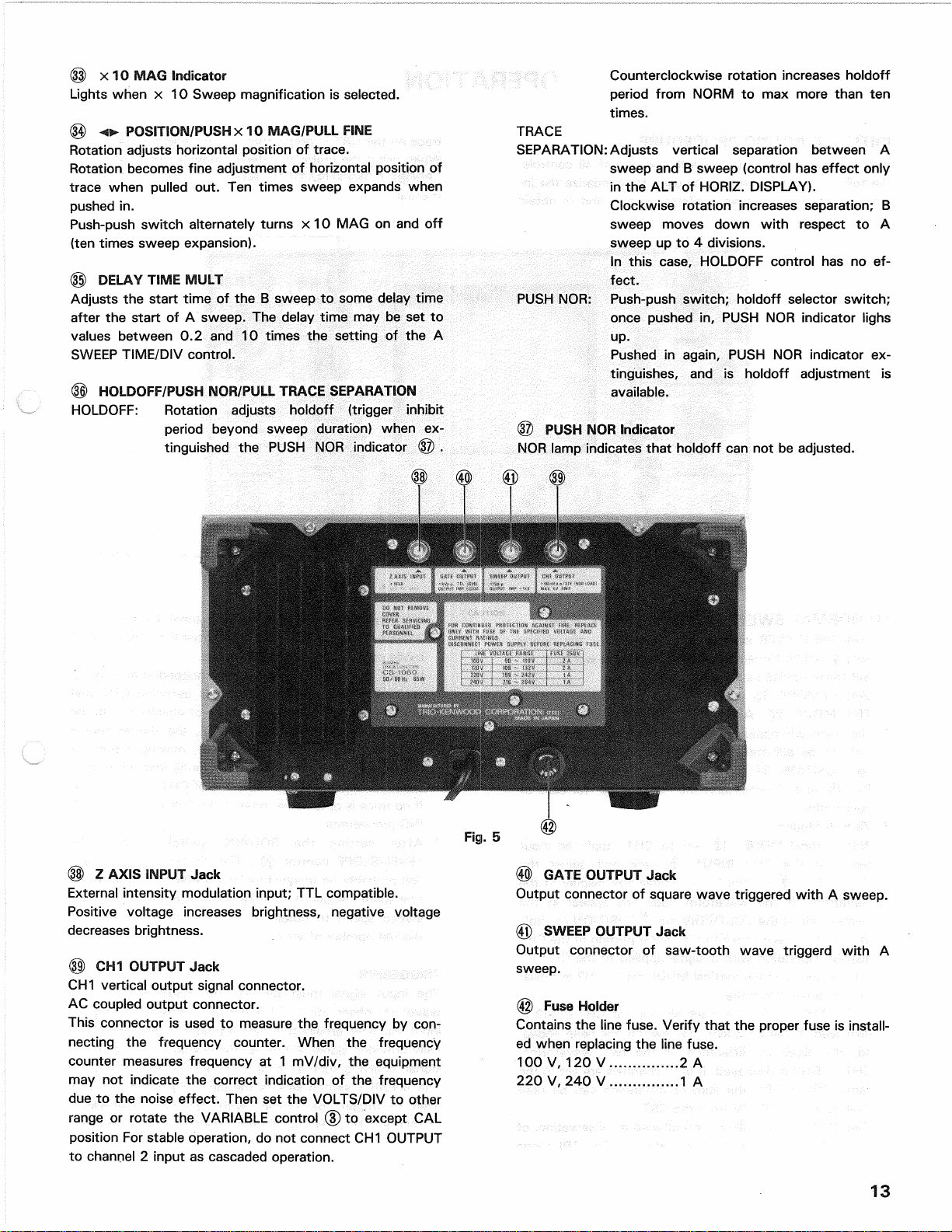
(§)Z AXISINPUTJack
Externalintensitymodulationinput;TTLcompatible.
Positivevoltageincreasesbrightness,negativevoltage
decreasesbrightness.
(§)CH1OUTPUTJack
CH1verticaloutputsignalconnector.
ACcoupledoutputconnector.
Thisconnectorisusedtomeasurethefrequencyby
con-
nectingthefrequencycounter.Whenthefrequency
countermeasuresfrequencyat1 mV/div,theequipment
maynotindicatethecorrectindicationofthefrequency
duetothenoiseeffect.ThensettheVOLTS/DIVtoother
rangeorrotatetheVARIABLEcontrol(3)toexceptCAL
positionForstableoperation,donotconnectCH1OUTPUT
tochannel2 inputascascadedoperation.
<®GATEOUTPUTJack
OutputconnectorofsquarewavetriggeredwithA sweep.
@SWEEPOUTPUTJack
Outputconnectorofsaw-toothwavetriggerdwithA
sweep.
@FuseHolder
Containsthelinefuse.Verifythattheproperfuseisinstall-
edwhenreplacingthelinefuse.
100V,120V 2 A
220V,240V 1 A
13
Fig.
5
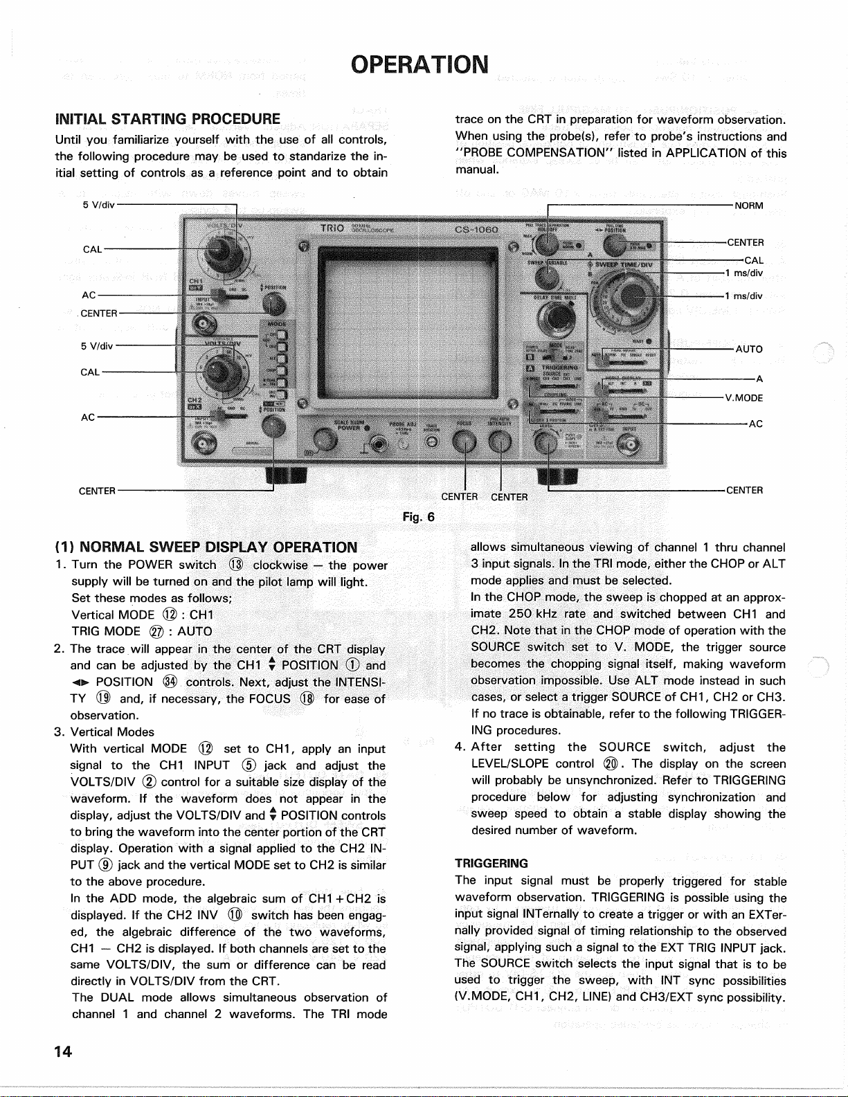
OPERATION
INITIALSTARTINGPROCEDURE
Untilyoufamiliarizeyourselfwiththeuseofallcontrols,
thefollowingproceduremaybeusedtostandarizethein-
itialsettingofcontrolsasa referencepointandtoobtain
traceontheCRTinpreparationforwaveformobservation.
Whenusingtheprobe(s),refertoprobe'sinstructionsand
"PROBECOMPENSATION"listedinAPPLICATIONofthis
manual.
Fig.
6
(1)NORMALSWEEPDISPLAYOPERATION
1.
TurnthePOWERswitch(Q)clockwise— thepower
supplywillbeturnedonandthepilotlampwilllight.
Setthesemodesasfollows;
VerticalMODE(@): CH1
TRIGMODE@ : AUTO
2.
ThetracewillappearinthecenteroftheCRTdisplay
andcanbeadjustedbytheCH10 POSITION<£>and
POSITION@)controls.Next,adjusttheINTENSI-
TY® and,ifnecessary,theFOCUS@ foreaseof
observation.
3.VerticalModes
WithverticalMODE@ settoCH1,applyaninput
signaltotheCH1INPUT(5)jackandadjustthe
VOLTS/DIV(2)controlfora suitablesizedisplayofthe
waveform.Ifthewaveformdoesnotappearinthe
display,adjusttheVOLTS/DIVandy POSITIONcontrols
tobringthewaveformintothecenterportionoftheCRT
display.Operationwitha signalappliedtotheCH2IN-
PUT(9)jackandtheverticalMODEsettoCH2issimilar
totheaboveprocedure.
IntheADDmode,thealgebraicsumofCH1+CH2is
displayed.
IftheCH2INV(Q)switchhasbeenengag-
ed,
thealgebraicdifferenceofthetwowaveforms,
CH1— CH2isdisplayed.Ifbothchannelsaresettothe
sameVOLTS/DIV,thesumordifferencecanberead
directlyinVOLTS/DIVfromtheCRT.
TheDUALmodeallowssimultaneousobservationof
channel1 andchannel2 waveforms.TheTRImode
allowssimultaneousviewingofchannel1 thruchannel
3inputsignals.IntheTRImode,eithertheCHOPorALT
modeappliesandmustbeselected.
IntheCHOPmode,thesweepischoppedatanapprox-
imate250kHzrateandswitchedbetweenCH1and
CH2.
NotethatintheCHOPmodeofoperationwiththe
SOURCEswitchsettoV.MODE,thetriggersource
becomesthechoppingsignalitself,makingwaveform
observationimpossible.UseALTmodeinsteadinsuch
cases,orselecta triggerSOURCEofCH1,CH2orCH3.
Ifnotraceisobtainable,refertothefollowingTRIGGER-
INGprocedures.
4.
AftersettingtheSOURCEswitch,adjustthe
LEVEL/SLOPEcontrol@).Thedisplayonthescreen
willprobablybeunsynchronized.RefertoTRIGGERING
procedurebelowforadjustingsynchronizationand
sweepspeedtoobtaina stabledisplayshowingthe
desirednumberofwaveform.
TRIGGERING
Theinputsignalmustbeproperlytriggeredforstable
waveformobservation.TRIGGERINGispossibleusingthe
inputsignalINTernallytocreatea triggerorwithanEXTer-
nallyprovidedsignaloftimingrelationshiptotheobserved
signal,
applyingsucha signaltotheEXTTRIGINPUTjack.
TheSOURCEswitchselectstheinputsignalthatistobe
usedtotriggerthesweep,withINTsyncpossibilities
(V.MODE,CH1,CH2,LINE)andCH3/EXTsyncpossibility.
14
*InternalSync
WhentheSOURCEselectionisinINT(V.MODE,CH1,
CH2,
LINE),theinputsignalisconnectedtotheinternal
triggercircuit.Inthisposition,a partoftheinputsignalfed
totheINPUT(5)or(9)jackisappliedfromthevertical
amplifiertothetriggercircuittocausethetriggersignal
triggeredwiththeinputsignaltodrivethesweep.
WhentheV.MODEpositionisselected,thetriggersource
isdependentupontheverticalMODEselection.
WhentheverticalMODEswitchisselectedinALTand
DUAL,thetriggersourcealternatesbetweenchannel1 and
channel2 witheachsweep.
WhentheverticalMODEswitchisselectedinALTandTRI,
thetriggersourcealternateschannel1 thruchannel3 with
eachsweep.
Thisisconvenientforcheckingamplitudes,waveshape,or
waveformperiodmeasurementsandevenpermits
simultaneousobservationoftwowaveformswhicharenot
relatedinfrequencyorperiod.However,thissettingisnot
suitableforphaseortimingcomparisonmeasurements.For
suchmeasurements,twoorthreetracesmustbetriggered
bythesamesyncsignal.
WhentheSOURCEselectionisinCH1,theinputsignalat
thechannel1 INPUT(5)jackbecomestriggerregardlessof
thepositionofverticalMODE.WhentheSOURCEselection
isinCH2,theinputsignalatthechannel2 INPUT(9)jack
becomestriggerregardlessofthepositionofvertical
MODE.
IftheSOURCEswitchissettotheLINEposition,
triggeringisderivedfromtheinputlinevoltage(50/60Hz).
Thisisusefulmeasurementsthatarerelatedtolinefre-
quency.
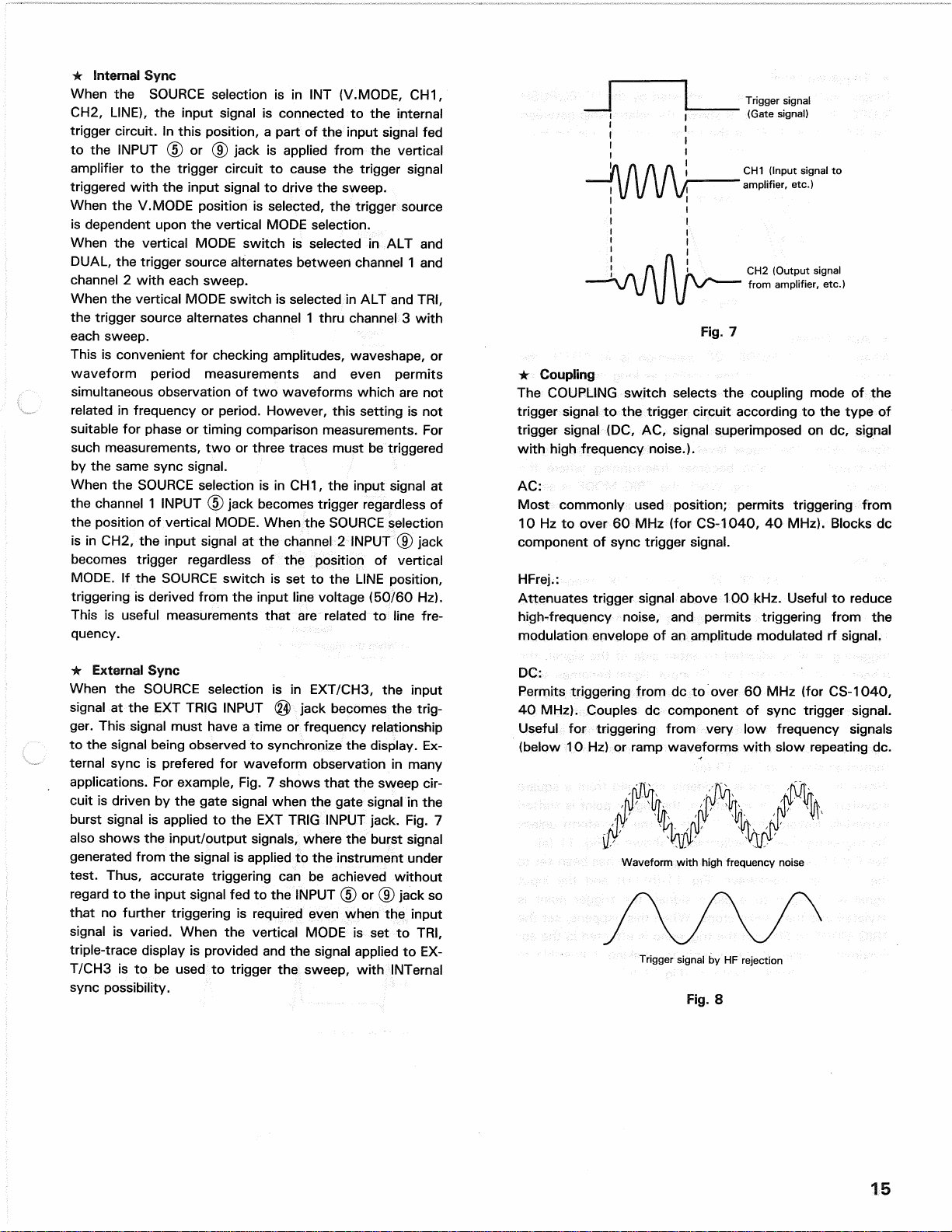
Triggersignal
(Gatesignal)
CH2(Outputsignal
fromamplifier,etc.)
Fig.
7
•Coupling
TheCOUPLINGswitchselectsthecouplingmodeofthe
triggersignaltothetriggercircuitaccordingtothetypeof
triggersignal(DC,AC,signalsuperimposedondc,signal
withhighfrequencynoise.).
AC:
Mostcommonlyusedposition;permitstriggeringfrom
10Hztoover60MHz(forCS-1040,40MHz).Blocksdc
componentofsynctriggersignal.
HFrej.:
Attenuatestriggersignalabove100kHz.Usefultoreduce
high-frequencynoise,andpermitstriggeringfromthe
modulationenvelopeofanamplitudemodulatedrfsignal.
*ExternalSync
WhentheSOURCEselectionisinEXT/CH3,theinput
signalattheEXTTRIGINPUT@>jackbecomesthe
trig-
ger.Thissignalmusthavea timeorfrequencyrelationship
tothesignalbeingobservedtosynchronizethedisplay.Ex-
ternalsyncispreferedforwaveformobservationinmany
applications.Forexample,Fig.7 showsthatthesweepcir-
cuitisdrivenbythegatesignalwhenthegatesignalinthe
burstsignalisappliedtotheEXTTRIGINPUTjack.Fig.7
alsoshowstheinput/outputsignals,wheretheburstsignal
generatedfromthesignalisappliedtotheinstrumentunder
test.Thus,accuratetriggeringcanbeachievedwithout
regardtotheinputsignalfedtotheINPUT(5)or(9)jackso
thatnofurthertriggeringisrequiredevenwhentheinput
signalisvaried.WhentheverticalMODEissettoTRI,
triple-tracedisplayisprovidedandthesignalappliedtoEX-
T/CHSistobeusedtotriggerthesweep,withINTernal
syncpossibility.
DC:
Permitstriggeringfromdctoover60MHz(forCS-1040,
40MHz).Couplesdccomponentofsynctriggersignal.
Usefulfortriggeringfromverylowfrequencysignals
(below10Hz)orrampwaveformswithslowrepeatingdc.
Waveformwithhighfrequencynoise
TriggersignalbyHFrejection
Fig.
8
15
CH1(Inputsignalto
amplifier,etc.)
LEVEL
•AutoTrigger
WhentheTRIGMODE® selectionisinAUTO,the
sweepcircuitbecomesfree-runningaslongasthereisno
triggersignal,permittinga checkofGNDlevel.Whena
trig-
gersignalispresent,thetriggerpointcanbedeterminedby
theLEVELcontrolforobservationasinthenormaltrigger
signal.
Whenthetriggerlevelexceedsthetriggersignal,
thetriggercircuitalsobecomesfree-runningwherethe
waveformstartsrunning.WhentheTRIGMODEissetto
NORMand/or,whenthetriggersignalisabsentorthe
trig-
geringlevelexceedsthesignalthereisnosweep.
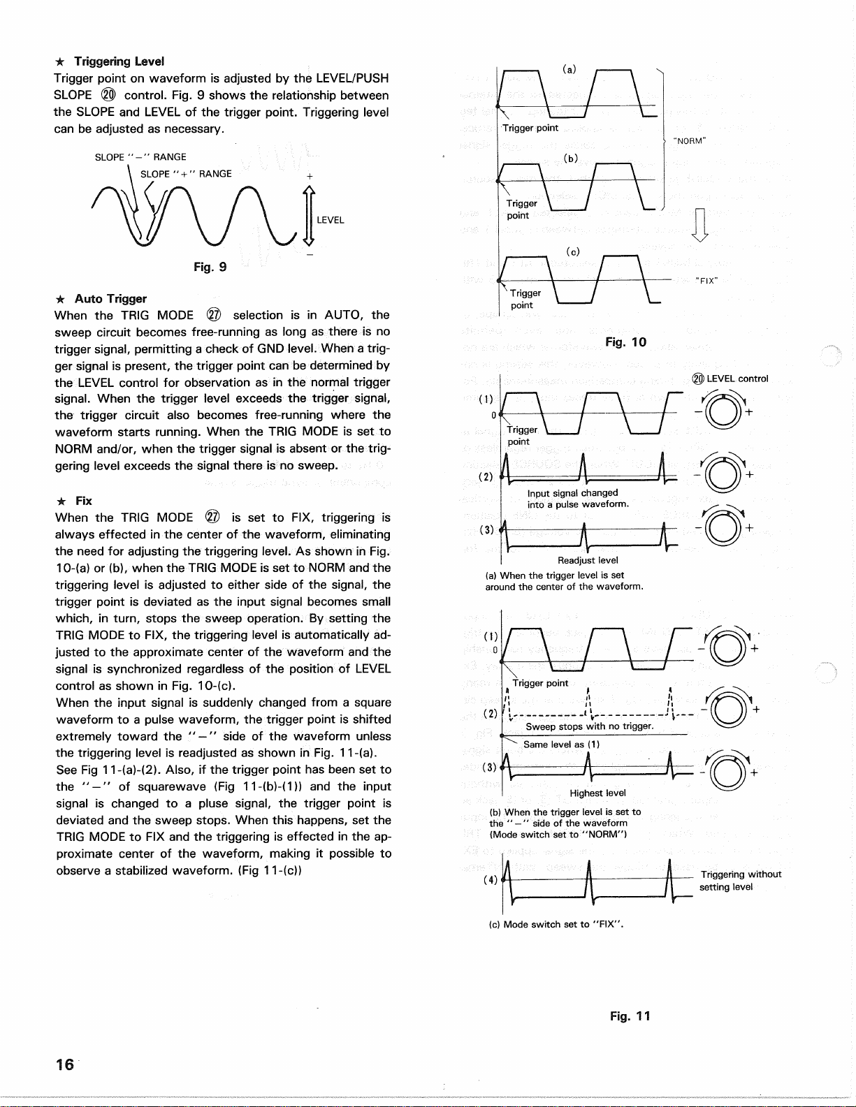
*Fix
WhentheTRIGMODE© issettoFIX,triggeringis
alwayseffectedinthecenterofthewaveform,eliminating
theneedforadjustingthetriggeringlevel.AsshowninFig.
10-(a)or(b),whentheTRIGMODEissettoNORMandthe
triggeringlevelisadjustedtoeithersideofthesignal,the
triggerpointisdeviatedastheinputsignalbecomessmall
which,
in
turn,
stopsthesweepoperation.Bysettingthe
TRIGMODEtoFIX,thetriggeringlevelisautomaticallyad-
justedtotheapproximatecenterofthewaveformandthe
signalissynchronizedregardlessofthepositionofLEVEL
controlasshowninFig.10-(c).
Whentheinputsignalissuddenlychangedfroma square
waveformtoa pulsewaveform,thetriggerpointisshifted
extremelytowardthe" —"sideofthewaveformunless
thetriggeringlevelisreadjustedasshowninFig.11-(a).
SeeFig11-(a)-(2).Also,ifthetriggerpointhasbeensetto
the" —"ofsquarewave(Fig11-(b)-(1))andtheinput
signalischangedtoa plusesignal,thetriggerpointis
deviatedandthesweepstops.Whenthishappens,setthe
TRIGMODEtoFIXandthetriggeringiseffectedintheap-
proximatecenterofthewaveform,makingitpossibleto
observea stabilizedwaveform.(Fig11-(c))
'NORM"
Fig.
10
LEVELcontrol
Inputsignalchanged
intoa pulsewaveform.
Readjustlevel
(a)Whenthetriggerlevelisset
aroundthecenterofthewaveform.
Samelevelas(1)
Triggeringwithout
settinglevel
(c)Modeswitchsetto
"FIX".
Fig.
11
16
*TriggeringLevel
TriggerpointonwaveformisadjustedbytheLEVEL/PUSH
SLOPE@)control.Fig.9 showstherelationshipbetween
theSLOPEandLEVELofthetriggerpoint.Triggeringlevel
canbeadjustedasnecessary.
SLOPE"-"RANGE
SLOPE" + " RANGE
Triggerpoint
Trigger
point
Trigger
point
"FIX"
Trigger
point
Triggerpoint
Sweepstopswithno
trigger.
Highestlevel
(b)Whenthetriggerlevelissetto
the"
—
" sideofthewaveform
(Modeswitchsetto"NORM")
Fig.
9
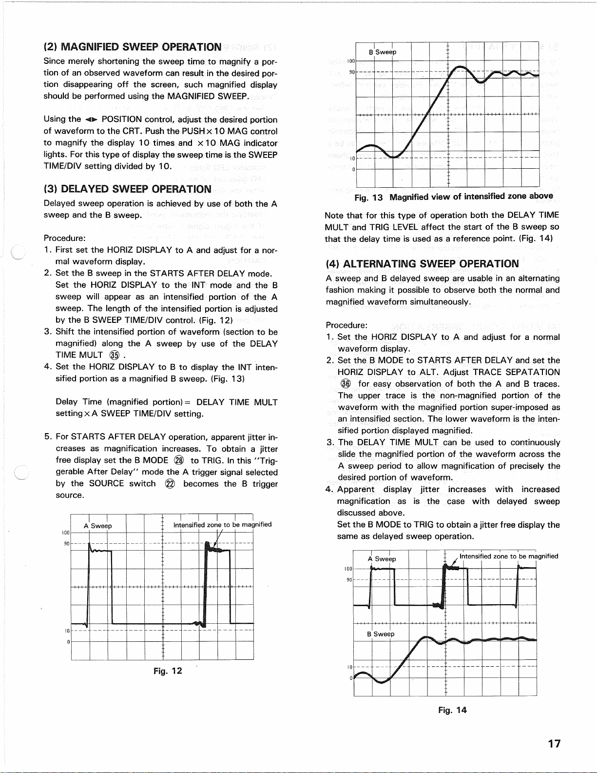
(2)MAGNIFIEDSWEEPOPERATION
Sincemerelyshorteningthesweeptimetomagnifya por-
tionofanobservedwaveformcanresultinthedesiredpor-
tiondisappearingoffthescreen,suchmagnifieddisplay
shouldbeperformedusingtheMAGNIFIEDSWEEP.
UsingthePOSITIONcontrol,adjustthedesiredportion
ofwaveformtotheCRT.PushthePUSHx 10MAGcontrol
tomagnifythedisplay10timesandx 10MAGindicator
lights.
ForthistypeofdisplaythesweeptimeistheSWEEP
TIME/DIVsettingdividedby10.
(3)DELAYEDSWEEPOPERATION
DelayedsweepoperationisachievedbyuseofboththeA
sweepandtheB sweep.
Procedure:
1.
FirstsettheHORIZDISPLAYtoA andadjustfora nor-
malwaveformdisplay.
2.
SettheB sweepintheSTARTSAFTERDELAYmode.
SettheHORIZDISPLAYtotheINTmodeandtheB
sweepwillappearasanintensifiedportionoftheA
sweep.Thelengthoftheintensifiedportionisadjusted
bytheB SWEEPTIME/DIVcontrol.(Fig.12)
3.Shifttheintensifiedportionofwaveform(sectiontobe
magnified)alongtheA sweepbyuseoftheDELAY
TIMEMULT© .
4.
SettheHORIZDISPLAYtoB todisplaytheINTinten-
sifiedportionasa magnifiedB sweep.(Fig.13)
DelayTime(magnifiedportion)= DELAYTIMEMULT
settingx A SWEEPTIME/DIVsetting.
5.ForSTARTSAFTERDELAYoperation,apparentjitterin-
creasesasmagnificationincreases.Toobtaina jitter
freedisplaysettheB MODE@ toTRIG.Inthis
"Trig-
gerableAfterDelay"modetheA triggersignalselected
bytheSOURCEswitch@ becomestheB trigger
source.
NotethatforthistypeofoperationboththeDELAYTIME
MULTandTRIGLEVELaffectthestartoftheB sweepso
thatthedelaytimeisusedasa referencepoint.(Fig.14)
(4)
ALTERNATINGSWEEPOPERATION
AsweepandB delayedsweepareusableinanalternating
fashionmakingitpossibletoobserveboththenormaland
magnifiedwaveformsimultaneously.
Procedure:
1.
SettheHORIZDISPLAYtoA andadjustfora normal
waveformdisplay.
2.
SettheB MODEtoSTARTSAFTERDELAYandsetthe
HORIZDISPLAYtoALT.AdjustTRACESEPATATION
(f§)foreasyobservationofboththeA andB traces.
Theuppertraceisthenon-magnifiedportionofthe
waveformwiththemagnifiedportionsuper-imposedas
anintensifiedsection.Thelowerwaveformistheinten-
sifiedportiondisplayedmagnified.
3.TheDELAYTIMEMULTcanbeusedtocontinuously
slidethemagnifiedportionofthewaveformacrossthe
Asweepperiodtoallowmagnificationofpreciselythe
desiredportionofwaveform.
4.
Apparentdisplayjitterincreaseswithincreased
magnificationasisthecasewithdelayedsweep
discussedabove.
SettheB MODEtoTRIGtoobtaina jitterfreedisplaythe
sameasdelayedsweepoperation.
Fig.
12
Fig.
14
17
BSweep
Fig.
13Magnifiedviewofintensifiedzoneabove
ASweep Intensifiedzonetobemagnified
ASweep ,Intensifiedzonetobemagnified
BSweep

(5)
X-Y
OPERATION
Forsomemeasurements,
an
externalhorizontaldeflection
signal
is
required.This
is
alsoreferred
toasanX-Y
measurement,where
theY
inputprovidesverticaldeflec-
tionand
X
inputprovideshorizontaldeflection.
X-Yoperationpermits
the
oscilloscope
to
performmany
types
of
measurements
not
possiblewithconventional
sweepoperation.
The
CRTdisplaybecomes
an
electronic
graph
of
twoinstantaneousvoltages.Thedisplaymaybe
a
directcomparison
oftwo
voltagessuch
as
duringphase
measurement,
or
frequencymeasurementwithLissajous
waveforms.
Touse
an
externalhorizontalinput,usethefollowingpro-
cedure;
1.
SettheHORIZDISPLAYswitch
to
X-Ytheposition.
2.
Use
the
channel
1
probe
forthe
verticalinputand
the
channel
2
probe
for
thehorizontalinput.
3.Adjusttheamount
of
horizontaldeflectionwiththeCH2
VOLTS/DIVandVARIABLEcontrols.
4.
TheCH2
(vertical)POSITION
(Q)
control
now
serves
as
the
horizontalpositioncontrol,
andthe
POSI-
TIONcontrol
is
disabled.
5.
All
synccontrolsaredisconnectedandhave
no
effect.
(6)
VIDEOSIGNALOBSERVATION
TheVIDEOFRAME/LINEswitchpermitsselection
of
ver-
tical
or
horizontalsyncpulse
for
sweeptriggeringwhen
viewingcompositevideowaveforms.
Inthe
LINEposition,
horizontalsyncpulses
are
selected
as
triggers
to
permit
viewing
of
horizontalline
of
video.
In
theFRAMEposition,
verticalsyncpulsesareselectedastriggers
to
permitview-
ing
of
verticalfieldsandframes
of
video.Whenobserving
thevideowaveforms,stabledisplay
is
obtained
onthe
screenregardlesstheTRIGLEVELcontrol.
Atmostpoints
of
measurement,
a
compositevideosignal
is
of
the
(—)
polarity,thatis,
the
syncpulsesarenegative
andthevideo
is
positive.Inthiscase,use
"
—"SLOPE.
Ifthewaveform
is
taken
ata
circuitpointwherethevideo
waveform
is
inverted,thesyncpulsesarepositiveand
the
video
is
negative.
In
thiscase,use
" + "
SLOPE.
(7)
SINGLESWEEPOPERATION
Thismode
of
display
is
useful
for
looking
atnon-
synchronous
or
onetimeevents.
Procedure:
1.
SettheTRIGMODE
© to
eitherAUTO
or
NORM.App-
ly
a
signal
of
approximatelythesameamplitudeandfre-
quencyasthesignalthatis
to
beobservedasthetrigger
signalandsetthetriggerlevel.
2.
Set
TRIGMODE
to
RESET
-
observethat
the
READY
indicatorLEDlights
to
indicatetheresetcondition.This
LEDgoes
out
whenthe
A
sweepperiod
is
completed.
3.Aftertheaboveset-up
is
completed
the
scope
is
ready
tooperate
in
theSINGLEsweepmode
of
operationafter
resetting
the
instrumentusing
the
RESETswitch.Input
of
the
triggersignalresults
in
oneandonlyonesweep
andREADYindicatorLEDgoesout.
18
CAUTION:
WiththeHORIZDISPLAYset
to
ALTthesimultaneous
observation
of
the
A
sweepand
B
sweepwaveforms
atSINGLEsweepmode
isnot
possible.Also
for
DUAL
orTRI
operationsimultaneousobservation
is
notpossibleusing
ALT
mode.
Setthe
unit
tothe
CHOPmodeinthiscase.
APPLICATIONS
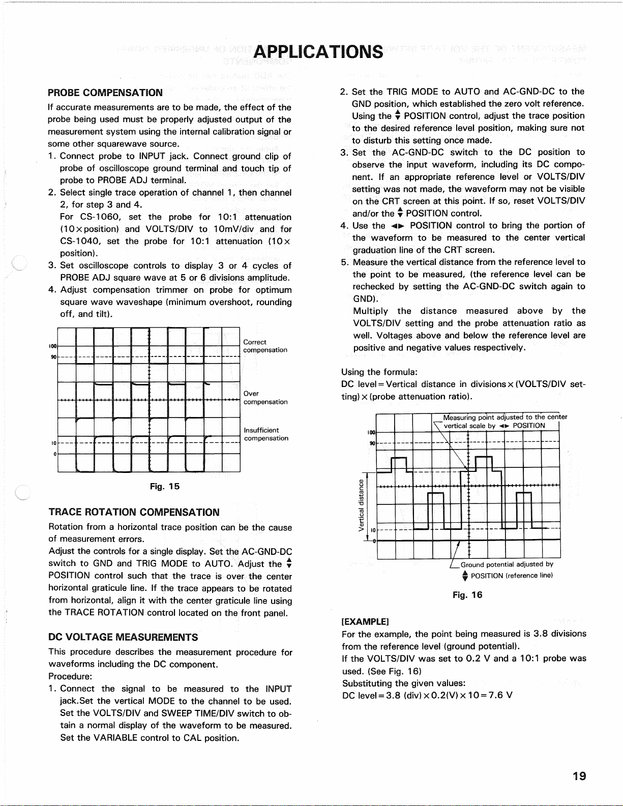
PROBECOMPENSATION
Ifaccuratemeasurements
aretobe
made,
the
effect
ofthe
probebeingusedmust
be
properlyadjustedoutput
ofthe
measurementsystemusing
the
internalcalibrationsignal
or
someothersquarewavesource.
1.
Connectprobe
to
INPUTjack.Connectgroundclip
of
probe
of
oscilloscopegroundterminal
and
touch
tipof
probe
to
PROBE
ADJ
terminal.
2.
Selectsingletraceoperation
of
channel
1,
thenchannel
2,
for
step
3 and4.
ForCS-1060,
setthe
probe
for10:1
attenuation
(1
Ox
position)
and
VOLTS/DIV
to
10mV/div
andfor
CS-1040,
setthe
probe
for10:1
attenuation
(10x
position).
3.
Set
oscilloscopecontrols
to
display
3 or4
cycles
of
PROBE
ADJ
squarewave
at5 or6
divisionsamplitude.
4.
Adjustcompensationtrimmer
on
probe
for
optimum
squarewavewaveshape(minimumovershoot,rounding
off,
and
tilt).
Correct
compensation
Over
compensation
Insufficient
compensation
Fig.
15
TRACEROTATIONCOMPENSATION
Rotationfrom
a
horizontaltraceposition
canbethe
cause
ofmeasurementerrors.
Adjust
the
controls
fora
singledisplay.
Setthe
AC-GND-DC
switch
toGNDand
TRIGMODE
to
AUTO.Adjust
the•
POSITIONcontrolsuchthat
the
trace
is
over
the
center
horizontalgraticuleline.
Ifthe
traceappears
tobe
rotated
fromhorizontal,align
it
with
the
centergraticulelineusing
theTRACEROTATIONcontrollocated
onthe
frontpanel.
DCVOLTAGEMEASUREMENTS
Thisproceduredescribes
the
measurementprocedure
for
waveformsincluding
theDC
component.
Procedure:
1.
Connect
the
signal
tobe
measured
tothe
INPUT
jack.Set
the
verticalMODE
tothe
channel
tobe
used.
Set
the
VOLTS/DIV
and
SWEEPTIME/DIVswitch
toob-
tain
a
normaldisplay
ofthe
waveform
tobe
measured.
Set
the
VARIABLEcontrol
toCAL
position.
2.
Setthe
TRIGMODE
to
AUTO
and
AC-GND-DC
tothe
GNDposition,whichestablished
the
zerovoltreference.
Using
the•
POSITIONcontrol,adjust
the
traceposition
to
the
desiredreferencelevelposition,makingsure
not
todisturbthissettingoncemade.
3.
Setthe
AC-GND-DCswitch
totheDC
position
to
observe
the
inputwaveform,including
itsDC
compo-
nent.
Ifan
appropriatereferencelevel
or
VOLTS/DIV
setting
wasnot
made,
the
waveform
maynotbe
visible
on
theCRT
screen
at
thispoint.
Ifso,
resetVOLTS/DIV
and/or
the•
POSITIONcontrol.
4.
Usethe<>•
POSITIONcontrol
to
bring
the
portion
of
thewaveform
tobe
measured
tothe
centervertical
graduationline
oftheCRT
screen.
5.Measure
the
verticaldistancefrom
the
referencelevel
to
thepoint
tobe
measured,
(the
referencelevel
canbe
rechecked
by
setting
the
AC-GND-DCswitchagain
to
GND).
Multiply
the
distancemeasuredabove
bythe
VOLTS/DIVsetting
andthe
probeattenuationratio
as
well.
Voltagesabove
and
below
the
referencelevel
are
positive
and
negativevaluesrespectively.
Using
the
formula:
DClevel
=
Verticaldistance
in
divisions
x
(VOLTS/DIVset-
ting)
x
(probeattenuationratio).
[EXAMPLE]
For
the
example,
the
pointbeingmeasured
is3.8
divisions
from
the
referencelevel(groundpotential).
If
the
VOLTS/DIV
wassetto0.2V anda 10:1
probe
was
used.
(See
Fig.
16)
Substituting
the
givenvalues:
DClevel
= 3.8
(div)
x
0.2(V)
x
10
= 7.6V
19
Measuringpointadjusted
tothe
center
verticalscale
by
POSITION
Verticaldistance
Groundpotentialadjusted
by
^POSITION(referenceline)
Fig.
16

MEASUREMENT
OFTHE
VOLTAGEBETWEEN
TWO
POINTS
ONA
WAVEFORM
Thistechnique
canbe
used
to
measurepeak-to-peak
voltages.
Procedure:
1.
Apply
the
signal
tobe
measured
tothe
INPUTjack.
Set
theverticalMODE
tothe
channel
tobe
used.
Setthe
AC-GND-DC
toAC,
adjustingVOLTS/DIV
and
SWEEP
TIME/DIV
fora
normaldisplay.
Setthe
VARIABLE
con-
trol
toCAL
position.
2.
Using
thew
POSITIONcontrol,adjust
the
waveform
positionsuchthat
oneofthetwo
pointsfalls
ona CRT
graduationline
and
that
the
other
is
visible
onthe
displayscreen.
3.Using
the<>•
POSITIONcontrol,adjust
the
second
point
to
coincidewith
the
centerverticalgraduationline.
4.
Measure
the
verticaldistancebetween
thetwo
points
andmultiplythis
bythe
setting
ofthe
VOLTS/DIV
con-
trol.
If
a
probe
is
used,furthermultiplythis
bythe
attenua-
tionratio.
Using
the
formula:
VoltsPeak-to-Peak
-Verticaldistance(div)
x
(VOLTS/DIVsetting)
x
(probe
attenuationratio)
Adjust
tothe
center
verticalscalewith
POSITION.
•
Points
tobe
measured
[EXAMPLE]
For
the
example,
thetwo
points
are
separated
by4.4
divi-
sionsvertically.
Setthe
VOLTS/DIVsetting
be0.2
V/div
and
the
probeattenuation
be
10:1.(SeeFig.
17)
ELIMINATION
OF
UNDESIREDSIGNAL
COMPONENTS
The
ADD
feature
canbe
convenientlyused
to
cancel
out
theeffect
ofan
undesiredsignalcomponentwhich
maybe
superimposed
onthe
signal
you
wish
to
observe.(See
Fig.
18)
Procedure:
1.
Apply
the
signalcontaining
an
undesiredcomponent
to
theCH1INPUTjackand
the
undesiredsignalitselfalone
to
theCH2
INPUTjack.
2.
Setthe
verticalMODE
to
DUAL(CHOP)andSOURCE
to
CH2.
VerifythatCH2represents
the
unwantedsignal
in
reversepolarity.
If
necessaryreversepolarity
by
setting
CH2
to
INV.
3.
Setthe
verticalMODE
to
ADD,SOURCE
toV.
MODE
and
CH2
VOLTS/DIV
and
VARIABLE
so
that
the
undesiredsignalcomponent
is
cancelled
as
much
as
possible.
The
remainingsignalshould
bethe
signal
you
wish
to
observealone
and
free
ofthe
unwantedsignal.
Signalcontainingundesiredcomponent
(Brokenlines:undesiredcomponentenvelope)
Undesiredcomponentsignal
Substituting
the
givenvalue:
Voltagebetween
two
points
=
4.4(div)
x
0.2(V)
x
10
=
8.8V
20
Vertical
distance
betweentwopoints
Fig.
17
Adjust
tothe
horizontal
scalewith
A
POSITION.
This manual suits for next models
1
Table of contents
Other Trio Test Equipment manuals


Popular Test Equipment manuals by other brands

Siemens
Siemens WLTS Application guide

Agilent Technologies
Agilent Technologies 8960 reference guide

Amprobe
Amprobe MEGATEST 5000 owner's manual

Baylan
Baylan BTM2Y user manual

Gossen MetraWatt
Gossen MetraWatt PROFITEST 2 DIN VDE 0100 operating instructions

Bacharach
Bacharach INJECTOR CALIBRATOR CD3 Installation & operation instruction


