Druck DPI 610 IS User manual

iK239 Issue No. 1
DPI 610 IS
PORTABLE PRESSURE CALIBRATOR/INDICATOR
USER GUIDE
K239
DPI 610 IS Portable Pressure Calibrator
Software version 1.XX
© Druck Ltd. 1999
This document is the property of Druck Limited and may not, either in part or whole, be
copied or otherwise reproduced, communicated in any way to third parties nor stored in any
Data Processing system, without the express written authority of Druck Limited.
Indicator Version
Hydraulic Calibrator Version
Calibrator Version
Is1pre_d.p65 23/03/99, 10:331

ii
K239 Issue No. 1
INTRINSIC SAFETY CONDITIONS OF USE
This instrument is designed to be intrinsically safe when operated
in accordance with the BASEEFA Certification document and
schedule (see Appendix 2).
BASEEFA Certificate of Conformity No. Ex 99E2002X
BASEEFA beinganApprovedCertificationBody,in accordancewith
Article 14 of the Council Directive of the European Communities of
18thDecember,1975(76/117/EEC)certifiesthat theapparatus has
been found to comply with harmonised European Standards:
EN 50014: 1992
EN 50020: 1994
and has successfully met the examination and test requirements
recorded in confidential report Number,
98(C)0818 (ERA Report Ref.3627/856), dated January, 1999
NOTE: Attention is drawn to Pages 4/5 of the Certificate
of conformity for electrical connection parameters
SPECIAL CONDITION OF USE
The DPI 610 IS Series Pressure calibrator is NOT capable of
withstanding the 500V r.m.s. electric strength test between
the external connectors and the frame of the apparatus as
required by Clause 6.4.12 of EN50020 and this must be taken
intoaccountwhenusing the apparatusforinputmeasurements
in a system.
EEx ia IICT4
Is1pre_d.p65 23/03/99, 10:332

iii K239 Issue No. 1
SAFETY
The Manufacturer has designed this product to be entirely safe when operated correctly.
lPlease pay close attention to the Safety Instructions outlined on this page and
elsewhere in this manual. They have been designed to protect the user from
personal injury and the equipment from damage.
Potentially hazardous operations are indicated in the text by means of a
hazard warning triangle. Specific warnings relating to each section of the
manual are given at the beginning of that section. On the instrument, this
symbol indicates that the user should refer to the User Manual.
lPlease observe the installation advice and any operational limits given in this
manual.
lThis equipment must only be used for the purpose for which it was designed
Electrical Safety
The instrument is designed to be completely safe when used with options and
accessories supplied by the manufacturer for use with the instrument.
Test leads
Only use the test leads supplied with this instrument; the test leads must not be used
with any other test equipment.
Toxic Materials
No toxic materials are employed in this equipment
Repair and Maintenance
The instrument must be maintained, either by the manufacturer or a competent person.
Please refer to supplier for details of approved service agents. A list of Druck
Subsidiaries who will be able to assist and advise is given on Page 38.
Software Issue
This guide contains operating instructions for instruments with software Version 1.XX.
This product meets the essential protection requirements of the relevant
EEC directives. Further details of applied standards may be found in the
product specification.
C E
!
WARNING This is a Class A product. In a domestic environment this product may
cause radio interference in which case the user may be required to take
adequate measures.
Is1pre_d.p65 23/03/99, 10:333

iv
K239 Issue No. 1
Specification
Pressure Ranges (InternalTransducers)
Accuracy
Combined non-linearity, Hysteresis and repeatability
70 mbar to 20 bar (Calibrator): 0.025% F.S.
35 bar to 700 bar (Indicator): 0.025% F.S.
70 bar to 400 bar (Hydraulic) 0.025% F.S.
Temperature Effects
±0.004% of reading/°C (averaged over -10° to -40°C w.r.t. 20°C)
Electrical Parameters
Voltage Inputs
Range: ±50V
Accuracy ±0.05% rdg, ±0.004% F.S.
Resolution 100mV max
Current Inputs
Range: ±55mA
Accuracy ±0.05% rdg, ±0.004% F.S.
Resolution 1mA max
Current sink
Range: 24 mA
Accuracy ±0.05% rdg, ±0.01% F.S.
Display
Size: 60x60 mm LCD Graphics
Reading ±99999, update rate 2 readings/sec
Environmental
Operating Temp.: -10°C to 50°C (Calibrated -10°C to 40°C)
Storage Temp: -20°C to 60°C
Calibration Temp: 21°C ±2°C
Sealing
Sealed to IP54
Physical
Size: 300 x170x140 mm
Weight: 3 kg
Is1pre_d.p65 23/03/99, 10:334

vK239 Issue No. 1
Introduction
General 1
Description of Procedures 1
Using the Guide 2
Summary of Functions 3
OPERATOR CONTROLS 3
DISPLAY 3
HARD KEY FUNCTIONS 4
SOFT KEYS 5
CURSOR KEYS 5
ELECTRICAL CONNECTIONS 6
Getting Started
Fitting Batteries 7
Switching On 7
Change Pressure Units 8
Voltage and Current Measurements 8
Typical Calibration Set-up (Pressure to Voltage) 9
Zero Display Reading 9
Making Measurements
Basic Mode (Task BASIC) 10
Pressure Transmitter (P-I) Task 10
Pressure Converter (P-P) Task 11
Voltage Output Pressure Transmitter (P-V) Task 11
Current to Pressure Converter (I-P) Task 12
Pressure Switch Test (P-Switch) Task 12
Pressure to Display (P-Display) Task 13
Leak Tests (Leak Test) Task 14
Transmitter Simulator (TX SIM) Task 15
Relief Valve Test (REL VALVE) Task 16
Advanced Task 17
General 17
Select Input 17
Ambient Temperature Measurement 17
Process Functions 18
Tare Process Function 19
Min/Max Process Function 20
Filter Process Function 20
Flow Function 21
% Span 21
Select Output 22
Contents
Is1pre_d.p65 23/03/99, 10:335

vi
K239 Issue No. 1
Advanced Task (contd.)
Electrical Outputs (Loop Power) 22
mA Step 23
mA Ramp 24
mA Value 26
Define New Task 26
Clear Task 26
Memory Operations 27
Saving Display or Datalog 27
Store Operations 27
Recalling Stored Data 27
Datalog Operations 28
Auto Log (Timer) 28
Manual Logging 28
Recall Datalog Files 29
Downloading Datalog Files 29
Delete Datalog Files 30
Using Set-up 30
General 30
Contrast 30
Store Mode 30
Calibration 31
Settings - Select Set-up Option 31
Units
31
Define Special Units
32
Language
32
RS232
32
Powerdown
32
Calibration 33
General 33
Calibration Check 33
Calibration Adjustment 34
General Procedures 34
Using The Calibration Menu 34
Temperature 35
ServiceApproved Service Agents 36
Contents (Contd.)
Is1pre_d.p65 23/03/99, 10:336

vii K239 Issue No. 1
Appendix 1 - Hydraulic Actuator version
Introduction 37
Safety Instructions 38
Preparation for Use 38
Bleeding the System 39
Operation 40
Draining the Hydraulic Fluid 40
Flushing, replenishing or Changing the Hydraulic Fluid 41
Appendix 2 - Baseefa Certificate of Conformity
Contents (Contd.)
Is1pre_d.p65 23/03/99, 10:337

viii
K239 Issue No. 1
Notes
(This page intentionally blank)
Is1pre_d.p65 23/03/99, 10:338

K239 Issue No.11
General
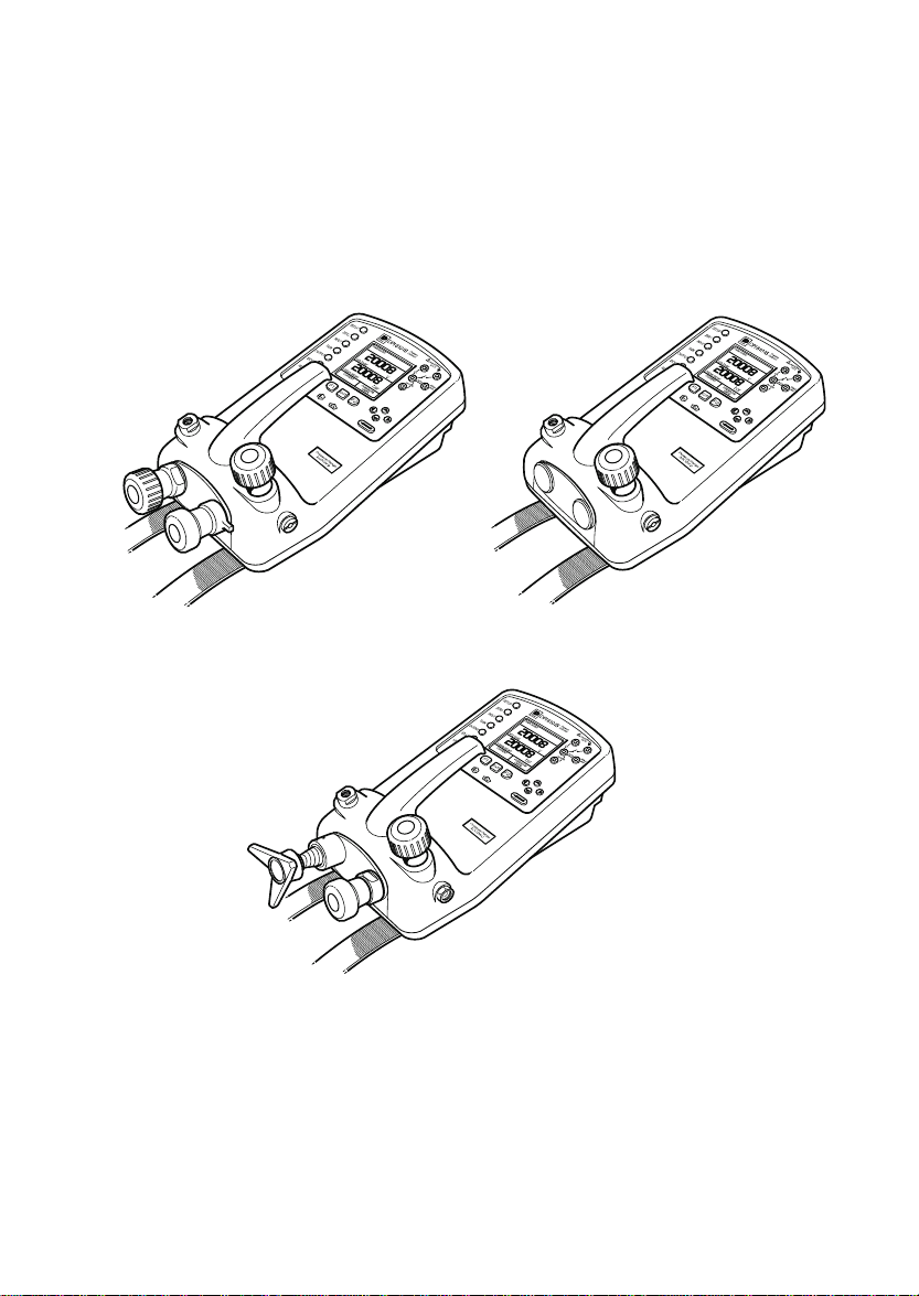
The DPI 610 is a rugged, portable precision instrument available either as an indicator
or calibrator for use in hazardous areas. Additionally, an intrinsically safe hydraulic
calibrator version (HC) is available.
The instrument is primarily used for calibrating instrumentation and systems over the
range -1 to 20 bar, (HC version to 400 bar). Used in conjunction with external transducers,
the range of the standard calibrator/indicator can be extended up to 700 bar.
The instrument is also capable of sinking an externally supplied current loop up to a
maximum current of 24 mA and measuring dc input voltages of ± 30V and dc currents
of ± 55 mA. Ambient temperature measurement is also provided.
The DPI 610 is powered by six alkaline C-cells and has an RS232 interface.
Important Notice
Zinc-carbon and zinc-chloride cells should NOT be used in this instrument.
Use only the battery types as shown in theTable on page 7.
Description of Procedures
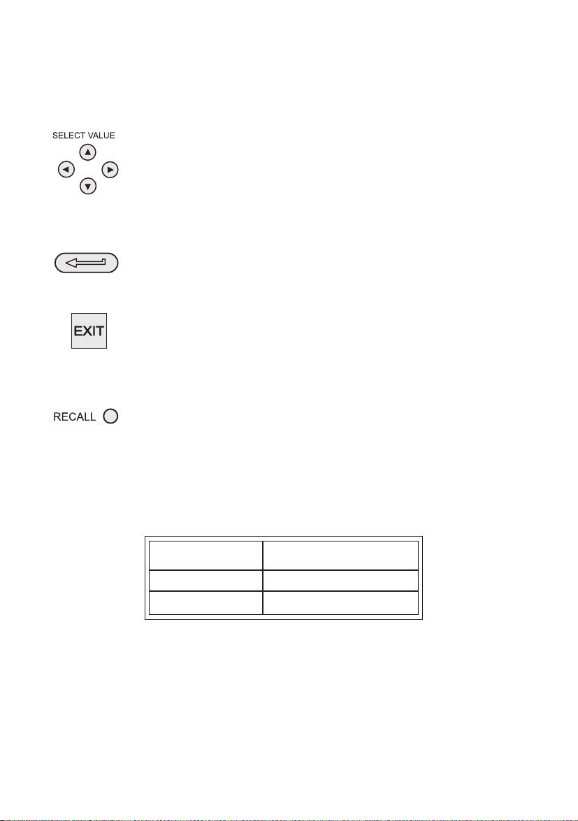
In the procedures outlined in this User Guide, hard (fixed function) and soft (variable
function) key operations are shown in bold type (e.g.) TASK and F1. These statements
mean press the TASK key and press the F1 key. Soft key operations can be allocated
to both the F1 and F2 keys. Where a specific soft function is referred to it is written in
bold italics (e.g.)
PROCESS
.
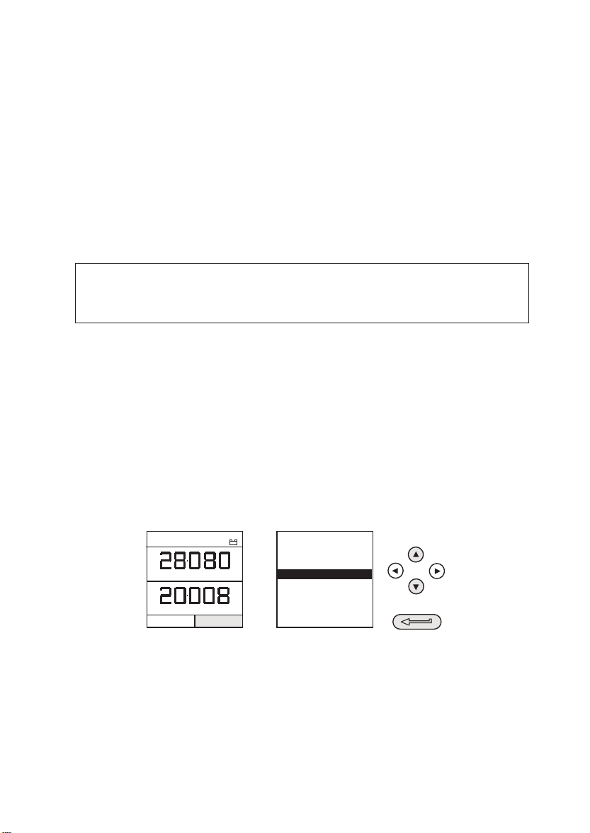
This instrument has a number of operating modes which are described in simplified
form in the following sections. Diagrams accompanying the procedures give typical
selection sequences and shaded controls indicate that this control key should be
pressed in the appropriate sequence. Diagrams should be read from left to right, top to
bottom where appropriate. A shaded display soft box indicates that the function key
immediately below that soft box should be pressed (either F1 for the left hand soft box
or F2 for the right). A typical diagram is shown below (e.g.).
In the above diagram the following key sequence is indicated.
(a) Press the F2 key (the key immediately below the
UNITS
soft box).
(b) Use the Up and Down cursor keys (only) to select the required option.
(If all keys shaded, use all these keys to select or enter data).
(c) Press the ENTER key.
INTRODUCTION Summary of Functions
SELECT UNITS
SELECT UNITS
OF PRESSURE
inHg
bar
hPa
Pa
PRESSURE INT
bar
VOLTAGE
V
CURRENT
UNITS
PRESSURE
TASK: BASIC
+
-
IS1_1_B.p65 23/03/99, 10:371

2
K239 Issue No.1
UsingThis Guide
The following key symbols are used in the procedure diagrams which follow
Shaded cursor keys indicate that a combination of these four
keys, Up, Down, Left and Right should be used to (e.g.) enter an
alpha numeric value or to select a function.
Indicates the ENTER key. Used to confirm an operation or a
selection. Shading indicates key operation.
Exit key, used to clear current menu selection and return to next
menu level above current level. Used as an escape key from
current operation. Shading indicates key operation.
Hardkey (total 7). Legend beside key symbol indicates function.
Shading indicates key operation.
Maximum Instrument Ratings
The following table shows the maximum measurement input ratings of the instrument
which should not be exceeded.
PRESSURE 120% FULL SCALE
VOLTAGE 30V d.c.
CURRENT 55 mA d.c.
INTRODUCTION Summary of Functions
Note 1: The display flashes if the input pressure, voltage or current overrange.
Note 2:
Max applied voltage for external loop supply = 30V dc (see Page 8).
IS1_1_B.p65 23/03/99, 10:372

K239 Issue No.13
Figure 1 - DPI 610 Keypad
DISPLAY
The display section of the instrument basically divides into four distinct sections. The
two main sections of the display are used to display a
Measurand (input parameter)
and
a
Source (output parameter).
The remaining sections are used as a status display area
and to define soft key functions. A typical display is shown below (e.g.),
OPERATOR CONTROLS (Figure 1)
These divide into two groups, the operator/display controls (shown in Figure 1) and the
pressure/vacuum generation components (Shown in Figure 2). The operator controls
and a typical display, common to all instrument versions, is shown below.
INTRODUCTION Summary of Functions
PRESSURE INT
bar
VOLTAGE
V
F2F1
Electrical Measurement
Input Sockets
Cursor Keys
Enter Key
Function (Soft) KeysOn/Off Key Hard Keys
Display
CURRENT PRESSURE
UNITS
max 30V
TASK: BASIC
DPI 610 IS
PRESSURE INT bar
VOLTAGE V
CURRENT
UNITS
PRESSURE
TASK: BASIC
+
-
Measurand display
(INPUT)
Source display
(INPUT)
Soft boxes
Status display
IS1_1_B.p65 23/03/99, 10:373

4
K239 Issue No.1
HARD KEY FUNCTIONS (Fig. 1)
INTRODUCTION Summary of Functions
yeKnoitcnuFegaPfeR
O/I .FFOdnaNOtnemurtsniehtnrutotdesusiyeksihT 7
*PUTES ehT PUTES noitarugifnoclarenegstnemurtsniehtotsseccasedivorpyek .yrevilednosretemaraptluafedniatrecotputeserahcihwsretemarap 13
OREZ ehT OREZ rodnarusaemdetcelesehtrehtieorezotdesuebnacyek orezotstpmettA.orezfo%5nihtiwsignidaeryalpsidehtfi,yalpsidecruos ,egassemrorrenanitlusertesfforegrala
,egralootoreZ
9
*TUPNI ehT TUPNI .deyalpsidsidnarusaemhcihwtcelesotdesusiyek 81
KSAT
ehT KSAT roftnemurtsniehtgnirugifnocyldiparfosnaemasadesusiyek ytnewteraerehT.noitarbilacecivedlanretxefosepyttnereffidforebmuna enindnademmargorp-erperahcihwfonevele,elbaliavasnoitarugifnocksat .elbanifedresuera
71-01
*TUPTUO ehT TUPTUO stuptuoecruosstnemurtsniehtfohcihwtcelesotdesusiyek
.deyalpsidsi 62-32
*EROTS stnemurtsniehtwohnopugnidnepeD EROTS siyeksiht,putessiedom
ni(sneercsyalpsid02otpuerotsotrehtiedesu TOHSPANS otro,)edom
nineercsagolyllaunam GOLATAD .edom 23,82
*LLACER
.yalpsidehtotneercsderotsylsuoiverpallacerotdesusiyeksihT ehtnognidnepeD EROTS rehtoesllaceryeksihtfonoitarepo,pu-tesedom nI.elifgolatadroneercsderotsylsuoiverpafotohspanseht EROTS ,edom
eht,syekrosrucehtgnisuyB.derotsneercstsalehtsyalpsidnoitceles .snoitacolyromemhguorhtkcabrodrawrofrehtiellorcsnacrotarepo
23,82
RETNE ehT RETNE ni,ro,)atadderetnetpecca(atadretneotrehtiedesusiyek .noitcelesnevigatpeccaot,syektfosehthtiwnoitcnujnoc 2
TIXE
ehT TIXE syektfosdnadrahrehtoehtllahtiwnoitcnujnocnisetarepoyek yletaidemmilevelehtot,levelunemroneercstnerrucehtmorftixeot sserp,levelunemynamorfyletelpmoctiuqoT.tignidecerp TIXE ehtlitnu
ECRUOS/ERUSAEM .deyalpsidsineercs
2
* These key funtions are not available in BASIC mode
IS1_1_B.p65 23/03/99, 10:374

K239 Issue No.15
SOFT KEYS (Fig.1)
Three soft keys, designated F1, EXIT and F2, are situated immediately below the
display as shown below. These keys have their function allocated by the instrument
software which is indicated in the bottom of the display (Voltage for F1 and Units for F2
in this example). They are used to select menu (program) options and are fully
described under the appropriate section headings.
CURSOR KEYS (Fig.1)
The cursor keys consist of a block of four keys, arranged as shown in Figure 1. They
are designated Up (Ù), Down (Ú), Left (×) and Right (Ø). In programs where options
need to be selected from a list, (e.g.) the TASK selection program, the Up and Down
cursor keys are used to highlight one of the options, from which it can be selected by
the ENTER key. In TASK mode, where more than one page of options are provided, the
Left (×) and Right (Ø) cursor keys will switch between pages.
INTRODUCTION Summary of Functions
Figure 2 - DPI 610 Calibrator Controls
Release Valve.
Releases system
pressure through vent
port. Use to gradually,
or completely reduce
pressure
Vent Port
Select positive or
negative pressure
Cursor Keys
Soft Keys F1, EXIT, F2
Electrical Inputs,
V, I, Switch and mA sink
External Interfaces under flap
Power, RS 232, External Transducer
Pump, pressurises
test port and internal
sensor. Use to approximately
set output pressure
Fine pressure adjustment.
Start with control screwed out
half way to allow fine adjustment
up or down.
Test port. Connect to unit under test.
G1/8" coupling. Use a sealing washer.
Hard keys
IS1_1_B.p65 23/03/99, 10:375

6
K239 Issue No.1
ELECTRICAL CONNECTIONS
Figure 3 - Electrical System Connections
Measurement
inputs and
Source
Outputs are made via the control panel sockets as
shown below.
Figure 4 - Electrical Measurement Inputs/Source Outputs
INTRODUCTION Summary of Functions
Protective cover
Close when not using connectors
External Transducer
RS 232
(Connect and
use in Safe Area
Only)
USE RS232
IN SAFE
AREA ONLY
Temperature Sensor
PRESSURE INT
bar
VOLTAGE
V
F2F1
Electrical Measurement
Input Sockets
CURRENT
UNITS
INPUTS
OUTPUTS
Output Window
Input Window
PRESSURE
max 30V
CAT II
TASK: BASIC
DPI 610 IS
IS1_1_B.p65 23/03/99, 10:376

K239 Issue No.17
The first time that the instrument is powered up, it will power up in BASIC mode with the
main screen displaying voltage in the measurand display area and pressure in the
source display area. To switch to
Current
as measurand, press F1 as shown. Similarly,
F1 to return to
Voltage
.
Note: No other keys are active in this mode and the instrument can only be
reconfigured by pressing the TASK key and selecting another mode.
Fitting Batteries
Getting Started
WARNING: BATTERIES MUST ONLY BE FITTED IN A SAFE AREA.
USE ONLY THE BATTERIES SPECIFIED INTHETABLE.
Caution:
Old batteries can leak and cause corrosion. Never leave
discharged batteries in the instrument. Old batteries should be
treated as hazardous waste and disposed of accordingly.
Switching On
Press the I/O switch on the front panel and proceed as follows.
Cover fixing screws
Six Alkaline C-cells
(Type only as Table)
Cover fixing screws
I/O
VOLTAGE
PRESSURE INT
bar
V
CURRENT
UNITS
PRESSURE
TASK: BASIC
CURRENT
PRESSURE INT
bar
mA
VOLTAGE
UNITS
PRESSURE
TASK: BASIC
PRESSURE INT
bar
VOLTAGE
V
CURRENT
UNITS
PRESSURE
TASK: BASIC
+
-
Low battery indicator
rerutcafunaM .oNepyT
rezigrenE39NEepyTlairtsudnI
rezigrenE2MA.C.41RL.39E
llecaruD41RL-0041NM
atraV2MA.C.41RLepyT4104.oN
llecorP41RL-0041NM
IS1_1_B.p65 23/03/99, 10:377

8
K239 Issue No.1
In BASIC mode, the unit is configured to carry out basic Pressure to Voltage (P to V) or
Pressure to Current (P to I) tests a typical test procedures follow.
Change Pressure Units
To change the pressure units proceed as follows. If the four units displayed are not the
units required, press TASK and select any task, other than BASIC, press SETUP and
proceed as detailed on page 31. To return to BASIC mode, press TASK and select
BASIC.
Voltage and Current Measurements
Connect the electrical input sockets as follows for voltage and current measurements.
Use the test leads provided and DO NOT push bare wires into the sockets.
Note:
Max applied voltage = 30V dc, Max input current = 55mA dc
Getting Started
55mA
Vin
mA in
mA Sink
max 30V
max
+
-
V
VOLTAGE
55mA
Vin
mA in
mA Sink
max 30V
max
CURRENT
(FROM EXTERNAL SOURCE)
+
-
SELECT UNITS
SELECT UNITS
OF PRESSURE
inHg
bar
hPa
Pa
PRESSURE INT
bar
VOLTAGE
V
CURRENT
UNITS
PRESSURE
TASK: BASIC
+
-
Note:
Max applied voltage for external loop supply = 30V dc
IS1_1_B.p65 23/03/99, 10:378

K239 Issue No.19
Typical Calibration Setup (Pressure toVoltage)
Connect a device under test to the instrument as shown below.
lGeneral Procedure
mUse the handpump to pressurise the system to the required level as
indicated on the display. Allow the display to settle and screw the
volume adjuster in or out as a fine adjustment to the required pressure.
Record the measurand (e.g.)
Voltage
, reading at each applied pressure.
Zero Display Reading
Both the input and output windows can be set to zero by operation of the ZERO key,
providing that the displayed reading is already within 5% of zero. To zero either the
INPUT
(Measurand) or
OUTPUT
(Source) windows, proceed as follows (e.g.),
Getting Started
PRESSURE INT
bar
VOLTAGE
F2F1
V
P
Ext Press. Source
(Indicator Only)
Pressure
Regulator
V
-+
CURRENT
PRESSURE
UNITS
Max 30V
CAT II
-
++
-
-
BARRIER
SAFE
SAFE
EXT
SUPPLY
TASK: BASIC
DPI 610 IS
ZERO
VOLTAGE
PRESSURE INT
bar
V
YES
ZERO VOLTAGE DC ?
NO
VOLTAGE
PRESSURE INT
bar
V
ZERO
INPUT
ZERO
OUTPUT
TASK: BASIC TASK: BASIC
ZERO
VOLTAGE
PRESSURE INT
bar
V
YES
ZERO INTERNAL SENSOR ?
NO
VOLTAGE
PRESSURE INT
bar
V
ZERO
INPUT
ZERO
OUTPUT
TASK: BASIC TASK: BASIC
IS1_1_B.p65 23/03/99, 10:379

10
K239 Issue No.1
Basic Mode (Task BASIC)
This instrument will power up in this mode the first time that it is used. To select BASIC
from any other task, press the TASK key and select BASIC and press the ENTER key.
BASIC mode is fully described in the Getting Started, section (see page 9).
PressureTransmitter (P-I)Task
The transmitter is energised from an external supply via a barrier as shown below.
Set Units
Making Measurements
Note:
If the four units displayed are not the units required, press SETUP, select
SETTINGS and refer to Page 31.
P
I
Ext Press. Source
(Indicator Only)
Pressure
Regulator
PRESSURE INT
bar
CURRENT
mA
F2F1
++
-
-
BARRIER
SAFE
SAFE
EXT
SUPPLY
max 30V
TASK : P-I
SNAPSHOT MODE
DPI 610 IS
IS1_1_B.p65 23/03/99, 10:3710

K239 Issue No.111
Pressure Converter (Pressure to Pressure)Task
Making Measurements
mIf required, change pressure units using the OUTPUT key.
USE RS232
IN SAFE
AREA ONLY
PRESSURE INT
bar
VOLTAGE
V
P
Ext Press. Source
(Indicator Only)
Pressure
Regulator
V
+
F2
F1
-
++
-
-
BARRIER
SAFE
SAFE
EXT
SUPPLY
max 30V
TASK : P-V
SNAPSHOT MODE
DPI 610 IS
mTesting a converter requires one pressure to be applied to the unit under
test (UUT) and another (converter output) to be measured. The additional
measurement is provided by the external transducer option. P-P task
configures the instrument to output pressure and to measure pressure.
If necessary, units may be changed with the INPUT and OUTPUT keys.
Note: Match pressure ranges to give required accuracy and avoid
overpressure. External pressure is displayed in the input window.
Voltage Output PressureTransmitter (P-V) Task
IS1_1_B.p65 23/03/99, 10:3711

12
K239 Issue No.1
Current to Pressure Converter (I-P)Task
Making Measurements
mUse the Up (Ù)and Down (Ú)cursor keys to adjust the loop current to the
required value. Alternatively, press ENTER and use cursor keys to enter a finite
value. Cursor keys can then be used to nudge the output either up or down.
If required, change pressure units with INPUT key. A flashing CHECK LOOP
message indicates either an open circuit supply loop (or no external supply).
Pressure SwitchTests (P-SWITCH)Task
mContact state will be shown on display. When contacts close, buzzer sounds.
mTo run switch test, close vent valve and press the RUN (F1) key.
mUsing the handpump, increase the applied pressure to just below the switch
operating point. Screw the volume adjuster in until the switch operates (the
operating pressure of the switch is then written to the display).
mReduce pressure until the switch releases (indicated by the switch symbol). The
release pressure is then written to the display and the hysteresis displayed.
IS1_1_B.p65 23/03/99, 10:3712
Table of contents
Other Druck Test Equipment manuals

Druck
Druck PTC200 User manual

Druck
Druck TRX User manual

Druck
Druck DPI 620 Genii Instruction Manual

Druck
Druck UPS-III User manual

Druck
Druck DPI 841 User manual

Druck
Druck InstruMetrics ADTS542F Setup guide

Druck
Druck ADTS 403R Use and care manual

Druck
Druck DPI 610E User manual

Druck
Druck DPI620 Genii User manual

Druck
Druck DPI 620 Genii User manual