Hioki ST4030 User manual

ST4030
ST4030A
Firmware Version 1.20
Additions and Changes
IMPULSE WINDING TESTER
EN
Feb. 2023 Revised edition 1
ST4030A976-01
ABXXXXABXXXX Model name Instruction Manual
[600629281]
HIOKI ST4030A976-01

HIOKI ST4030A976-01

ST4030A976-01
Contents
1 Overview................................................................................................................................. 1
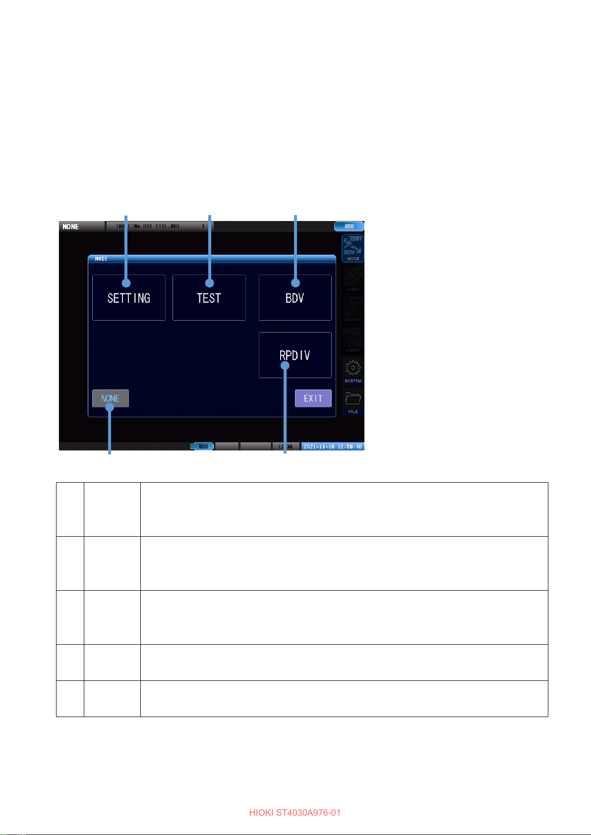
2 Selecting the Measurement Mode .......................................................................................... 2
3 Rise Time................................................................................................................................ 3
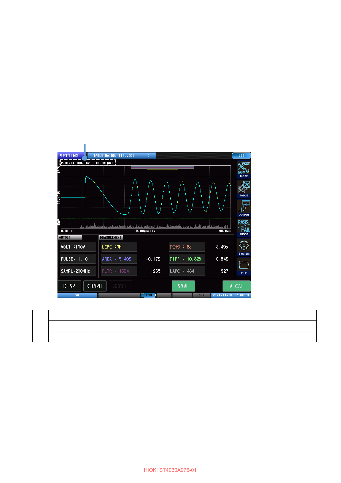
3.1 Waveform Graph Display .................................................................................................. 3
3.2 Setting the Rise Time Calculation Formula ....................................................................... 4
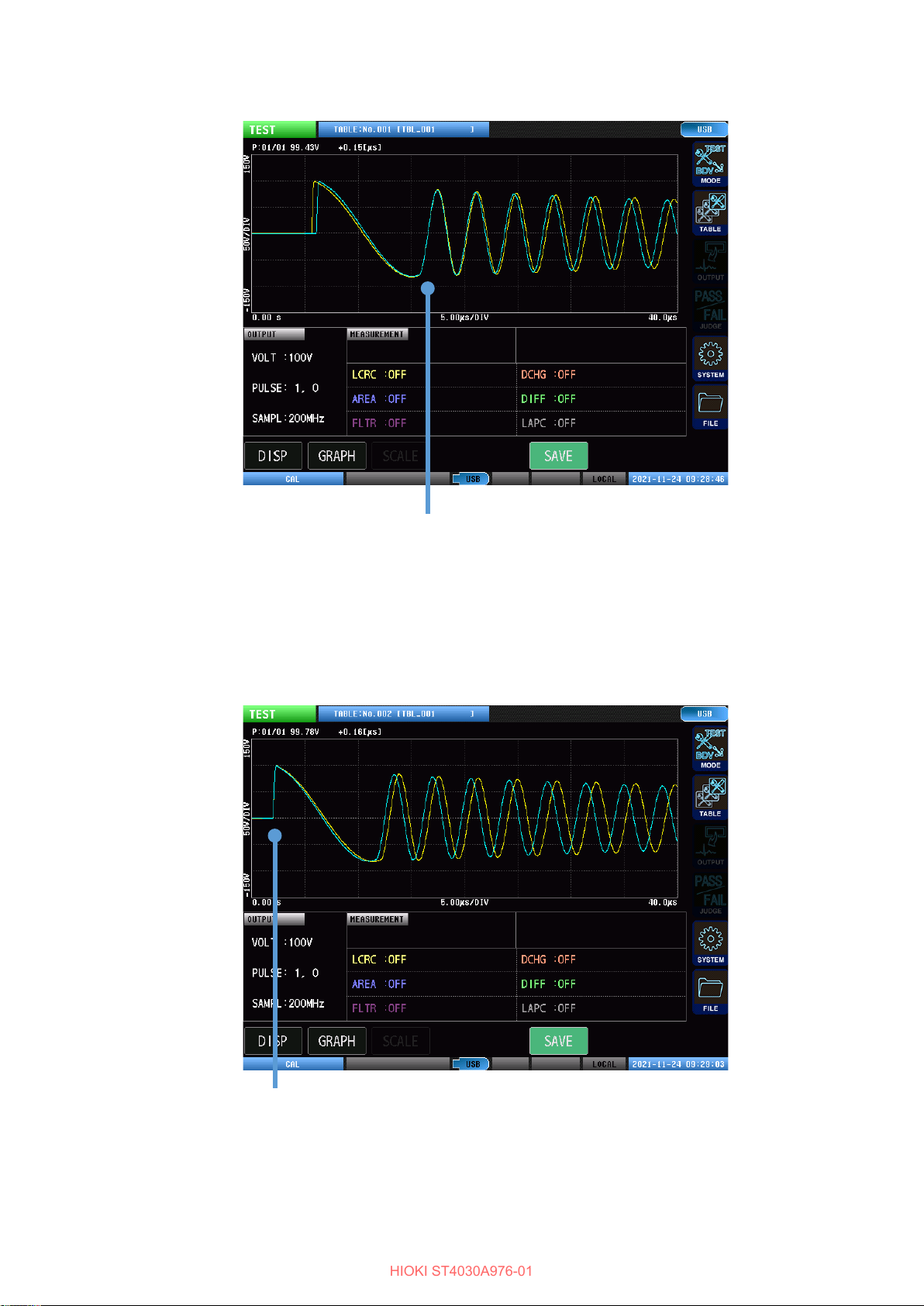
4 Waveform Trigger Position...................................................................................................... 5
4.1 Setting Waveform Trigger Positions.................................................................................. 5
5 Automatically Setting the Waveform Judgment Scope and Judgment Threshold Values........ 7
5.1 Automatically Setting the Waveform Judgment Scope...................................................... 8
5.2 Automatically Setting the Waveform Judgment Threshold Values .................................... 9
5.3 Waveform Judgment Threshold Values Formulas............................................................11
5.4 Compatibility of Automatically Configured Waveform Judgment Scope and
Judgment Threshold Values ........................................................................................... 12
6 Continuous Application ......................................................................................................... 13
6.1 Enabling Continuous Application..................................................................................... 13
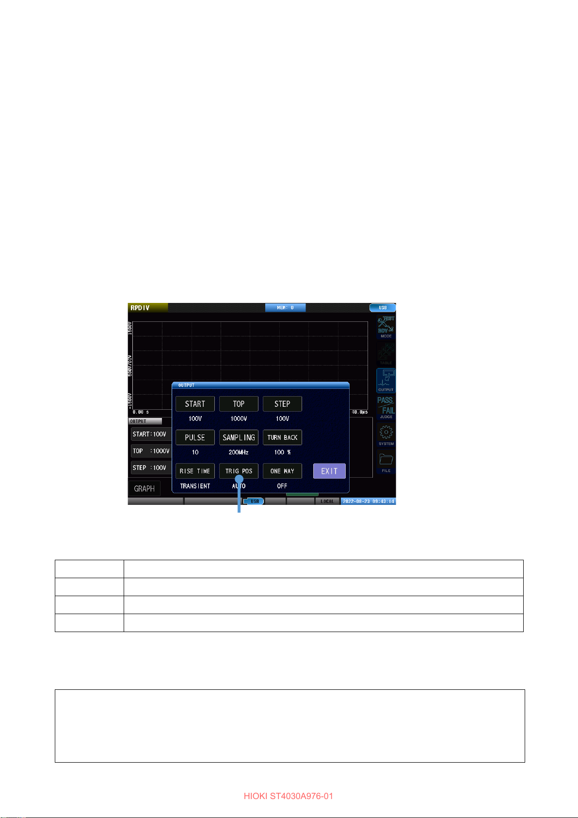
7 Discharge Starting Voltage Testing (RPDIV)......................................................................... 14
7.1 Screen Configuration ...................................................................................................... 14
7.2 Starting Testing and Checking Test Results .................................................................... 15
7.3 Recorded Data Display................................................................................................... 17
7.4 Applied Voltages ............................................................................................................. 18
7.5 Number of Applied Pulses............................................................................................... 19
7.6 Sampling Frequency and Number of Sampling Data...................................................... 20
7.7 Return Conditions ........................................................................................................... 21
7.8 Rise Time ........................................................................................................................ 22
7.9 Trigger Position ............................................................................................................... 23
7.10 Discharge Starting Voltage Judgment Conditions......................................................... 24
8 Automatic Voltage Adjustment .............................................................................................. 25
8.1 Global Automatic Voltage Adjustment ............................................................................. 26
8.2 Table-specific Automatic Voltage Adjustment.................................................................. 27
8.3 Screen Display................................................................................................................ 28
9 Manual Voltage Adjustment .................................................................................................. 29
9.1 Screen Display................................................................................................................ 30
10 Degaussing Pulse/Measurement Pulse Detection Signal Output ....................................... 31
HIOKI ST4030A976-01

11 Extension to Area Detection Threshold Settings ................................................................. 32
11.1 Screen Display.............................................................................................................. 34
12 Fixing Startup Mode............................................................................................................ 35
13 Permanently Enabling the Interlock Function...................................................................... 36
14 Permanently Enabling Level Operation of the EXT. I/O STOP Pin...................................... 36
15 Background Color ............................................................................................................... 37
16 Auto Saving of Files ............................................................................................................ 38
17 Extension to the Voltage Error Setting ................................................................................ 39
18 Expansion of System Information ....................................................................................... 40
19 Other Changes ................................................................................................................... 41
19.1 Communication Commands.......................................................................................... 41
19.2 BDV Mode..................................................................................................................... 41
19.3 File Screen.................................................................................................................... 41
19.4 STOP Button................................................................................................................. 41
19.5 Downgrading................................................................................................................. 41
HIOKI ST4030A976-01

1
1 Overview
The following functionality has been added to version 1.20 of the firmware:
•Measuring impulse voltage rise time
•Changing the positioning of master and measured waveforms
•Automatically setting waveform judgment scope and threshold values
•Applying voltage pulses continuously
•Performing discharge starting voltage testing that complies with the IEC 61934 procedure
•Changing the screen to a background color that’s easy to see for printing
•Automatically saving only data that is associated with a FAIL judgment
•Reducing voltage variability caused by variations in workpiece characteristics
•Adjusting the applied voltage value during testing without changing the applied voltage value setting
•Determining whether output pulses are degaussing or measurement pulses
•Setting separate upper and lower limit values for area judgment
•Changing the instrument’s operation so that it always starts up in the same mode
•Changing the instrument’s operation so that the interlock function is always enabled (cannot be undone)
•Changing the instrument’s operation to switch the EXT. IO STOP pin from edge operation to level operation
(cannot be undone)
•New communication commands
•Other
HIOKI ST4030A976-01

2
2 Selecting the Measurement Mode
An RPDIV measurement mode has been added for models equipped with the ST9000 Discharge Detection Upgrade.
Tap [MODE] on the measurement screen to display a measurement mode selection window. You can select from
five measurement modes.
1 SETTING Selects test conditions settings mode.
The instrument
will acquire test conditions settings, judgment condition settings, and a
master waveform.
2 TEST Selects test mode.
The instrument will call up the test conditions set in test conditions settings mode and use
them to test workpieces.
3 BDV Selects insulation breakdown testing (BDV) mode.
The instrument will perform impulse testing by gradually increasing the voltage applied to
the workpiece under test to determine the voltage at which insulation breakdown occurs.
4 NONE Selects no-voltage-application mode.
Output from the instrument will be disabled for safety reasons.
5 RPDIV Tests discharge status by performing impulse testing in which the applied voltages comply
with the IEC 61934 procedure. *1
*1: Models equipped with ST9000 Discharge Detection Upgrade onl y.
2
3
4
5*1
1
HIOKI ST4030A976-01

3
3 Rise Time
This functionality measures rise time.
It has been added to test conditions settings mode, test mode, BDV mode, and RPDIV mode.
3.1 Waveform Graph Display
The rise time is displayed at the top left of the waveform graph.
1 P:XX/XX Number of applied pulse / total number of pulses*1
xxxV Maximum peak voltage value for the response waveform
+X.XX[μs] Rise time*2
*1: During continuous application, only the number of applied pulses is shown.
*2: The display will switch between crest and tail length depending on the selected calculation formula.
1
HIOKI ST4030A976-01

4
3.2 Setting the Rise Time Calculation Formula
This section describes how to enable/disable display of waveform rise times and set the formula used to calculate
them.
Test conditions settings mode (Measurement screen) [MODE] > [SETTING] > [OUTPUT] > [RISE TIME]
BDV mode (Measurement screen) [MODE] > [BDV] > [OUTPUT] > [RISE TIME]
RPDIV mode (Measurement screen) [MODE] > [RPDIV] > [OUTPUT] > [RISE TIME]
RPDIV mode screen
1. Tap [RISE TIME] (rise time display format).
Enable/disable the waveform rise time display and set the calculation formula.
OFF Disables calculation and display of rise time.
30%to90% Uses the lightning impulse voltage waveform calculation formula. Displays the
crest and tail length.
0%to100% Uses the switching impulse voltage waveform calculation formula. Displays the
crest and tail length.
10%to90% Uses the lightning impulse current waveform calculation formula. Displays the
crest and tail length.
TRANSIENT Uses the transient response calculation formula. Displays the rise time.
In this case, the rise time is the time required for the voltage to increase from
10% to 90% of 0 V to the initial peak voltage.
1
HIOKI ST4030A976-01

5
4 Waveform Trigger Position
This functionality allows you to select the method used to position the master waveform and measured waveforms.
It has been added to test conditions settings mode, test mode, BDV mode, and RPDIV mode.
4.1 Setting Waveform Trigger Positions
Test conditions settings mode (Measurement screen) [MODE] > [SETTING] > [OUTPUT] > [TRIG POS]
BDV mode (Measurement screen) [MODE] > [BDV] > [OUTPUT] > [TRIG POS]
RPDIV mode (Measurement screen) [MODE] > [RPDIV] > [OUTPUT] > [TRIG POS]
Example RPDIV mode screen
1. Tap [TRIG POS] (trigger position).
AUTO Aligns waveforms’ display positions based on their second zero-cross position. *1
MINUS Aligns waveforms just before they approach 0 V from their minimum values *1
FALL Aligns waveforms’ display positions based on their initial zero-cross positions. *1
RISE Aligns waveforms’ display positions based on their rising edges.
*1: If the trigger position cannot be detected due to the condition of the voltage waveform, the setting will be changed
automatically to another condition.
To use the same setting as used by firmware older than version 1.10, select [AUTO].
1
IMPORTANT
Setting the trigger position to any setting other than AUTO will cause the LC and RC values waveform
processing scope to diverge from the resonance range.
In such cases, the LC and RC values will differ from values calculated based on the LCR resonance
circuit’s equivalent circuit, but they can still be used for judgment purposes.
HIOKI ST4030A976-01

6
Waveform trigger position: AUTO
The locations of the second zero-cross of the master waveform and measured waveform
are aligned on the screen.
Waveform trigger position: RISE
The locations of the rising edges of the master waveform and the measured waveform
are aligned on the screen.
HIOKI ST4030A976-01

7
5 Automatically Setting the Waveform Judgment Scope and Judgment
Threshold Values
The judgment scope and judgment threshold values used during voltage calibration can be set automatically.
Automatic configuration can be used to determine provisional settings for use in testing of judgment operation and
determining judgment threshold values.
Values can be set separately using the following judgment functions:
• Surface comparison judgment [AREA]
• Differential surface area comparison judgment [DIFF AREA]
• Flutter detection judgment [FLUTTER]
• Secondary differential detection judgment [LAPLACIAN]
• LC and RC values judgment [LCRC AREA] *1
*1: The judgment scope for LC and RC values judgment is set automatically.
HIOKI ST4030A976-01

8
5.1 Automatically Setting the Waveform Judgment Scope
Surface area comparison judgment, differential surface area comparison judgment, flutter detection judgment, and
secondary differential detection judgment
(Measurement screen) [MODE] > [SETTING] > [JUDGE] > [AREA], [DIFF AREA], [FLUTTER], [LAPLACIAN] >
[AUTO SET]
1. Tap [AUTO SCOPE].
OFF Disables automatic configuration of the judgment scope.
ALL Includes the entire acquired waveform length in the judgment scope. *1
Enables the judgment function.
ORIGINAL Sets the judgment scope so that it consists primarily of the self-resonance scope. *2
Enables the judgment function.
*1: This setting can be used for general judgment.
*2: This is the same scope as used in the firmware prior to version 1.10.
1
HIOKI ST4030A976-01

9
5.2 Automatically Setting the Waveform Judgment Threshold Values
Surface area comparison judgment, differential surface area comparison judgment, flutter detection judgment, and
secondary differential detection judgment
(Measurement screen) [MODE] > [SETTING] > [JUDGE] > [AREA], [DIFF AREA], [FLUTTER], [LAPLACIAN] >
[AUTO SET]
1. Tap [AUTO LIMIT] and select whether to configure threshold values automatically.
OFF Disables automatic configuration of threshold values.
ON Sets threshold values automatically.
Enables the judgment function.
2. If setting threshold values automatically, tap [VAR IATION] and select whether to add the equivalent of 6 σof
variation in judgment values (as a variability value).
OFF Does not add variability.
ON Adds variability.
3. Tap [MARGIN] and set the amount of allowance (margin value) to give threshold values when setting them
automatically.
2 31
HIOKI ST4030A976-01

10
LC and RC values judgment
(Measurement screen) [MODE] > [SETTING] > [JUDGE] > [LCRC AREA] > [AUTO SET]
1. Tap [AUTO LIMIT] and select whether to configure threshold values automatically.
OFF Disables automatic configuration of threshold values.
ON Sets threshold values automatically.
Enables the judgment function.
2. If setting threshold values automatically, tap [VAR IATION] and select whether to add the equivalent of 6 σof
variation in judgment values (as a variability value).
OFF Does not add variability.
ON Adds variability.
3. If setting the LC threshold value automatically, tap [MARGIN LC] and set the amount of allowance (margin value)
to give the threshold value.
4. If setting the RC threshold value automatically, tap [MARGIN RC] and set the amount of allowance (margin value)
to give the threshold value.
2 31 4
HIOKI ST4030A976-01

11
5.3 Waveform Judgment Threshold Values Formulas
Threshold values are automatically set using the following formulas:
AREA upper limit + Average of AREA judgment measured values during voltage calibration*1
+ Margin setting
+ Variability measured value
AREA lower limit - Average of AREA judgment measured values during voltage calibration*1
- Margin setting
- Variability measured value
DIFF AREA + Average of DIFF AREA judgment measured values during voltage calibration*1
+ Margin setting
+ Variability measured value
FLUTTER + Average of FLUTTER judgment measured values during voltage calibration*1
+ (Average of FLUTTER judgment measured values during voltage calibration) ×
margin setting
+ Variability measured value
LAPLACIAN + Average of LAPLACIAN judgment measured values during voltage calibration
+ (Average of LAPLACIAN judgment measured values during voltage calibration) ×
margin setting
+ Variability measured value
LCRC AREA LC upper
limit
+ Average of LC judgment measured values during voltage calibration
+
(Average of LC judgment measured values during voltage calibration) × margin setting
+ Variability measured value
LCRC AREA LC lower
limit
- Average of LC judgment measured values during voltage calibration
- (Average of LC judgment measured values during voltage calibration) × margin setting
- Variability measured value
LCRC AREA RC
upper limit
+ Average of RC judgment measured values during voltage calibration
+
(Average of RC judgment measured values during voltage calibration) × margin setting
+ Variability measured value
LCRC AREA RC lower
limit
- Average of RC judgment measured values during voltage calibration
-
(Average of RC judgment measured values during voltage calibration) × margin setting
- Variability measured value
*1: Under ideal conditions, the average of AREA judgment and DIFF AREA judgment measured values is 0. The
average value may be slightly greater than 0 because waveforms acquired during a large number of attempted
measurements may diverge slightly from the master waveform.
HIOKI ST4030A976-01

12
5.4 Compatibility of Automatically Configured Waveform Judgment
Scope and Judgment Threshold Values
Make the following settings to configure firmware version 1.10 for the same operation as [AUTO SET] automatic
configuration under the firmware prior to version 1.10.
Surface area comparison judgment, differential surface area comparison judgment, flutter detection judgment, and
secondary differential detection judgment
AUTO SET AUTO SCOPE AUTO LIMIT VA RI AT I O N MARGIN
OFF OFF ON ON Set value.
ON ORIGINAL ON ON Set value.
LC and RC values judgment
AUTO SET AUTO SCOPE AUTO LIMIT VA RI AT I O N MARGIN
No setting Fixed to ON ON ON Set value.
When a settings file saved using the firmware prior to version 1.10 is loaded, the data will be converted to the above
settings.
Since the waveform judgment scope and judgment threshold settings have been expanded, you may encounter
changes in control when checking the status of settings using communication commands. For more information,
please see the Communication Command Instruction Manual.
HIOKI ST4030A976-01

13
6 Continuous Application
This setting applies voltage pulses continuously from the start of measurement until measurement stops due to
STOP button input.
Testing can also be started and stopped using communications or the external control terminal.
6.1 Enabling Continuous Application
(Measurement screen) [MODE] > [SETTING] > [OUTPUT] > [PULSE]
1. Tap [CONTINUOUS] to select the continuous application setting.
OFF Performs measurement according to the number of applied pulses and the number of
degaussing pulses.
ON Applies voltage pulses continuously.
1
IMPORTANT
•No degaussing pulses are applied during continuous application.
•During continuous application, the screen will be redrawn after each applied pulse, and the previously applied
pulse waveform will be cleared.
•To display multiple previously applied pulse waveforms, enable overlay display of waveforms.
•During continuous application, the instrument will only record waveform data for the last pulse waveform to
be applied.
•When judgment is enabled, only the judgment results for the last pulse waveform to be applied will be
displayed.
HIOKI ST4030A976-01

14
7 Discharge Starting Voltage Testing (RPDIV)
This function tests discharge status by performing impulse testing in which the applied voltages comply with the
IEC 61934 procedure. *1
The operation procedure is the same as for BDV mode, but there are differences in the conditions set as part of the
testing process.
*1: Models equipped with ST9000 Discharge Detection Upgrade onl y.
7.1 Screen Configuration
1
Graph display Displays waveform graphs.
2 Menu icons MODE : Selects the measurement mode.
OUTPUT : Sets the test conditions.
JUDGE : Sets the judgment conditions.
SYSTEM : Configures the system.
FILE : USB host
3 [GRAPH] Sets the graph display.
4
Test conditions settings
display
Displays the settings for the application start voltage, max. voltage, and voltage
change width.
5
Judgment value display Displays the voltage setting and judgment values during testing.
6 [SAVE] Saves the test results to USB flash drive.
7
Measurement results
display area
Displays the test results.
1 2
3 4 5 6 7
HIOKI ST4030A976-01

15
7.2 Starting Testing and Checking Test Results
Testing is started by pressing the START button on the instrument. (It can also be started using communications or
the external control terminal.)
When testing completes, the test results will be output to the screen, communications, and external control terminals
(EXT. I/O).
Impulse testing is carried out by incrementing the voltage by the voltage change width, from the set applied voltage
to the maximum applied voltage, and recording the incidence of discharge. Once the maximum applied voltage has
been reached, impulse testing is applied by decrementing the voltage by the voltage change width and recording
the incidence of discharge.
1 Voltage
monitor
Displays the current applied voltage value.
2 Judgment
values
DCHG:XXσMax. deviation of discharge amount
Vpeak:XXσMax. misalignment width from standard of the peak voltage value
FREQ:XXσMax. misalignment width from standard of the vibration frequency
3
Measurement
results
PDIV
:
XXXXV (XXXXV) Partial discharge inception voltage
Test voltage value (measured voltage value)
RPDIV:XXXXV (XXXXV) Repeated partial discharge inception voltage
Test voltage value (measured voltage value)
MAX V: XXXXV (XXXXV) Return voltage
Test voltage value (measured voltage value)*1
RPDEV:XXXXV (XXXXV) Repeated partial discharge extinction voltage
Test voltage value (measured voltage value)
REF VAL:XXXXV (XXXXV) RPDEV reference value
Test voltage value (measured voltage value)*2
PDEV:XXXXV (XXXXV) Partial discharge extinction voltage
Test voltage value (measured voltage value)
REF VAL: XXXXV (XXXXV) PDEV reference value
Test voltage value (measured voltage value)*3
1
2
3
HIOKI ST4030A976-01

16
*1: Test voltage after switching from the rising voltage to the falling voltage process.
*2: To take into account variability in discharge incidence, the largest test voltage that does not exceed the test
voltage that resulted in a discharge incidence of 50% or more during the falling voltage process is recorded.
The value is not displayed if the voltage is the same as [RPDEV].
*3: To take into account variability in discharge incidence, of the test voltages that resulted in a discharge incidence
of 0% during the falling voltage process, the highest voltage value that is less than the [RPDEV] reference value
is recorded.
The value is not displayed if the voltage is the same as [PDEV].
HIOKI ST4030A976-01
Other manuals for ST4030
1
This manual suits for next models
1
Table of contents
Other Hioki Test Equipment manuals

Hioki
Hioki 3403 User manual

Hioki
Hioki 3157 User manual

Hioki
Hioki ST5680 User guide

Hioki
Hioki 3244-60 User manual

Hioki
Hioki 3805-50 User manual

Hioki
Hioki IR4053 User manual

Hioki
Hioki HiTESTER 3540 User manual

Hioki
Hioki FT3151 User manual

Hioki
Hioki HiLogger 3145-20 User manual

Hioki
Hioki Power HiTester 3193 User manual

Hioki
Hioki MEMORY HiCORDER 8855 Instruction manual

Hioki
Hioki 3288-20 User manual

Hioki
Hioki FT6031 User manual

Hioki
Hioki 9263 User manual

Hioki
Hioki 7016 User manual

Hioki
Hioki IR4055 User manual

Hioki
Hioki SS7012 User manual

Hioki
Hioki 3159 User manual

Hioki
Hioki FT6031 User manual

Hioki
Hioki FT6380-50 User manual