Trion Comfort-D75 User manual

Table of Contents
Introduction����������������������������������������������������������������������������������������������� 2
Contents ��������������������������������������������������������������������������������������������������� 2
Unit Dimensions ��������������������������������������������������������������������������������������� 3
Specications ������������������������������������������������������������������������������������������� 4
Unit Location��������������������������������������������������������������������������������������������� 5
Install Location���������������������������������������������������������������������������������������6-7
Ducting ����������������������������������������������������������������������������������������������������� 8
Wiring �������������������������������������������������������������������������������������������������� 9-11
Electrical Requirements�������������������������������������������������������������������������� 12
Condensate Removal����������������������������������������������������������������������������� 12
Operation�������������������������������������������������������������������������������������������13-14
Maintenance������������������������������������������������������������������������������������������� 14
Parts Diagram����������������������������������������������������������������������������������������� 15
Warranty ������������������������������������������������������������������������������������������������� 16
Whole House Central Dehumidier
Comfort-DTM
Models: D75 and D95
266314-301 05/12
Please complete the following on the day of the installation�
Homeowner to retain for their future informational purposes�
Unit Model Number ___________________________
Serial Number _______________________________
Installation Date______________________________
Installing Contractor Name _____________________
Installing Contractor Phone _____________________

2
The benets of a properly humidied environment are many. They include personal
comfort as well as the preservation of furniture, draperies, carpets, wooden oors
and cabinets, paintings, pianos, etc� Higher humidity levels can also increase the
growth-rate of mold, bacteria, viruses, and even dust mites in the home� Your
home can be more comfortable at a warmer temperature with drier air than without
controlling humidity during the humid summer months� Since every degree of
temperature change represents about 3% to 5% of the total cooling costs, each
degree warmer you can set the thermostat can represent a signicant annual
savings�
During the cooling season, warm, moist air inltrates the home and must be cooled.
When cooled, this air can still be humid as air conditioners are designed to cool the
air, not dehumidify the air. A small amount of dehumidication may be a benet of
air conditioners, but they actually work harder and longer to cool the air when the
air is moist. Only by using a whole house dehumidier to reduce the humidity in the
entire home's air, can a balance between humidity levels, temperature, comfort,
and energy costs be optimized�
Introduction
Contents
The following items should be included with your Trion Comfort-D Dehumidier.
▪ Comfort-D75 or Comfort-D95 Dehumidier
▪ Installation/Operation Manual
▪ Condensate Drain Trap
▪ (4) Adjustable Support Legs
If any items are not found, please contact Trion Customer Service at 800-884-0002
to acquire replacements�
The following are a list of items that may be required for a complete installation:
▪ 8 inch (D75) or 10 inch (D95) exible duct to isolate vibrations from return duct.
▪ Ducting (Length and size based on type of installation and unit size.
See pages 6-7 of manual for installation types.)
▪ Remote Humidistat
▪ Condensate Pump
▪ 8 inch (D75) or 10 inch (D95) “take offs” for connection to HVAC duct work
▪ ¾” PVC pipe and ttings for completion of drain to pump, outside space,
or code approved service drain
▪ Level (unit must be level or slightly tilted toward drain outlet to drain properly)
▪ 18-20 gauge thermostat wire
Caution: Read the entire manual carefully and completely
before installing this product. Installation and maintenance
should be completed by qualied personnel. Installation
contrary to these guidelines may void warranty.
3
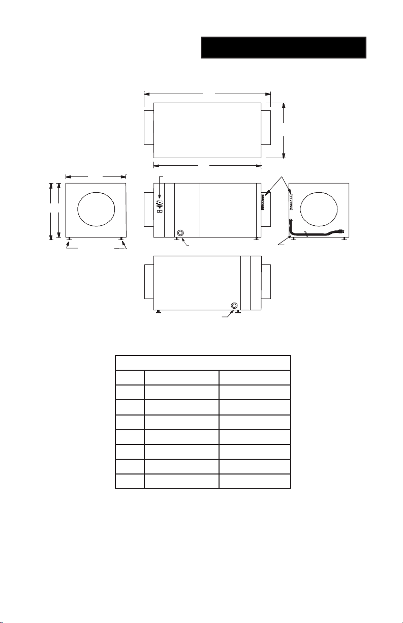
Unit Dimensions
A
C
B
B
Return Supply
FG
sseccAretliF
Filter Access
3/4" NPT Drain
3/4" NPT Drain Option
Factory Installed Plug
120 V Power Cord
Grounded - 90"
Service Access
Adjustable
Legs 1/4"- 1"
Low Voltage Terminal Strip
Humidistat Blower Control
TOP VIEW
FRONT VIEW
RIGHT SIDE
LEFT SIDE
BACK VIEW
D
E
Dimension Table
Comfort-D75 Comfort-D95
A 27�25 inch 29�25 inch
B 13�00 inch 14�25 inch
C 23�25 inch 25�25 inch
D 12�75 inch 14�25 inch
E 13�75 inch 15�25 inch
F 8�00 inch dia� 10�00 inch dia�
G 8�00 inch dia� 10�00 inch dia�
4
Model D75 D95
Capacity(@80°F,60% RH) 74 Pints/Day 95 Pints/Day
Temperature Range 50-95°F 50-95°F
Volts/Hertz 120V, 60Hz 120V, 60Hz
FLA (@80°F, 60% RH) 6�7 Amps 10�8 Amps
LRA (@80°F, 60% RH) 46�5 Amps 59�0 Amps
Inlet Diameter 8 inch round 10 inch round
Outlet Diameter 8 inch round 10 inch round
Unit Dims. (LxWxH) 27.25"x13.00"x12.75" 29.25"x14.25"x14.25"
Filter Dims (LxWxH) 11.75"x11.75"x2.00" 13.75"x13.75"x2.00"
Filter Efciency MERV 11 MERV 11
Compressor Size 5/8 HP 3/4 HP
Fan Motor Size 90 W 115 W
Refrigerant R-410A R-410A
Refrigerant Amount 17�5 oz 16�0 oz
Weight (Shipping Weight) 65 lbs (80 lbs) 90 lbs (105 lbs)
Energy Star Rated Yes No
ETL (USA & Canada) ANSI/UL STD 474,
Applicable Sections of ANSI/UL STD 1995,
CAN/CSA STD� C22�2 No�-92-197
Specications

5
The Comfort-D can be installed in a variety of locations to meet the owner's
needs as listed below� In all cases keep the following cautions in mind:
1� The unit is designed to be installed indoors in a space that is protected from
rain, ooding and/or other forms of excess water. Unit is not designed to be
exposed to chlorinated pool conditions or spaces where unit will be exposed
to corrosive chemicals or conditions�
2� Install the unit with space to access the front panel for maintenance and service�
Also allow easy access to the lter cover panel. DO NOT INSTALL UNIT
WITH THE FRONT PANEL OR FILTER COVER PANEL INACCESSIBLE.
3� Avoid discharging the air directly at people, over the water in pool areas, or
other areas or objects where dehydration or evaporation of moisture is not
desired�
4� If used near wet areas, be certain there is NO chance the unit could fall
into the water or be splashed and that it is wired into a GROUND FAULT
INTERRUPTER protected circuit�
5� A secondary drain pan MUST be placed under the unit if installed above a
living area or above an area where water leakage could cause damage (see
local codes for other requirements)
6. DO NOT position the Comfort-D directly on structural members where noise or
vibration may be objectionable. The unit is equipped with adjustable support
feet to raise and level the unit from the mounting surface, these adjustable
feet should be utilized to provide improved drainage from the drain pan and
should be adjusted to tilt slightly toward the drain utilized.
7� The Comfort-D should be located near the existing air handling system to
minimize the required ductwork for connecting of the Comfort-D to the existing
air handling system� When the remote control option is used, the control
(humidistat) unit must be located in the space that is to be conditioned. The
control (humidistat) may be low voltage (24 volt) and should be connected to
the Comfort-D with code approved, low voltage thermostat cable�
8� When locating the Comfort-D in areas of extreme heat or high humidity,
>120-degrees/90% humidity, additional external insulation may be required to
prevent undesired condensation on the exterior of the unit.
Unit Location

6
Comfort-D Dehumidiers are designed for installing as a Whole House Dehumidi-
er, but in some instances, Spot Dehumidication may be necessary. See below
for the type of installation that best ts the situation:
Whole Home Dehumidier Installations:
In a Basement or Crawl Space with an Existing Forced Air HVAC System
If the structure in which the Comfort-D System is to be installed has an existing
forced air HVAC system, utilize the HVAC system to make the Comfort-D System
installation easier and provide better system performance�
Basement or Crawl Space Installation: Install a separate 8" (D75) or 10” (D95)
return for the Comfort-D in a central area of the structure or if the return ducting is
adequate tap into the existing return duct system near the return air grill. Duct the
supply of the Comfort-D System to the return ducting of the existing HVAC system.
(See diagram on next page.) The fan interlock provision must be utilized for proper
system performance�
In an Attic with an Existing Forced Air HVAC System
ALWAYS install a secondary drain pan with a drain or oat interrupt for condensa-
tion under the Comfort-D in an attic to prevent condensate overow that may drip
down, damaging the ceiling or living space below�
Install a separate 8" (D-75) or 10” (D-95) return for the Comfort-D in a central area
of the structure or if the return ducting is adequate, tap into the existing return duct
system near the return air grill� Duct the supply of the Comfort-D System to the
return ducting of the existing HVAC system. The fan interlock provision must be
utilized for proper system performance�
Installation in a Structure with Two Forced Air HVAC Systems
Attach the Comfort-D return to an independent return from the upper level� At-
tach the Comfort-D supply to the return of the basement HVAC system. This will
promote circulation of air through the whole structure from the upper level to the
lower level through the Comfort-D. If the Comfort-D is not connected to both HVAC
systems, it may not control the humidity of the entire structure� The fan interlock
provision should be connected to the lower, ducted, HVAC system and must be
utilized for proper system performance�
Installation in a Structure with No Existing Forced Air HVAC System
When installing the Comfort-D in a structure that does not have a forced air HVAC
system, a single return for the Comfort-D should be installed in central open area
of the structure� DO NOT locate the return in a bathroom or a kitchen� The supply
of the Comfort-D should be located in the remote areas of the structure (such as
bedrooms, den, etc...). By ducting this way, the air inside the structure will circu-
late through the Comfort-D to be ltered and dehumidied. 5" (D75) or 6" (D95)
diameter duct is recommended for branches to the bedrooms, 6" (D75) or 8" (D95)
diameter duct is recommended for branches to larger areas�
Install Location
7
Install Location
Spot Dehumidier Installations:
Installation in a Sealed Crawl Space or Sealed Attic
When installing the Comfort-D in a sealed crawlspace or sealed attic, a single re-
turn for the Comfort-D should be installed in the central open area of the structure�
If the area is open without partitions, return ducting is not necessary� Supply duct-
ing is recommended to enhance the performance of the system, a minimum length
of supply duct, 3’ to 6’ will aid in air distribution. If the area(s) being served are
divided by walls or partitions, a supply and return duct system is recommended�
In all cases, sound duct design practices must be followed such as those provided
in ACCA Manual “D”, or ASHRAE’s “Fundamentals of Air System Design”.
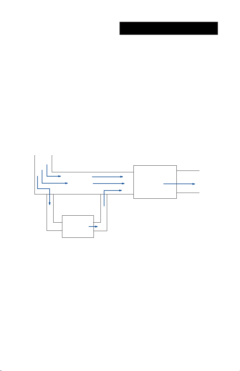
Typical Installation Diagram
Comfort-D
RETURN AIR
AIR HANDLER SUPPLY AIR

8
Ducting
Installing Duct
The Comfort-D is equipped with either an 8" (D75) or 10” (D95) round duct collar
inlet, and an 8" (D75) or 10” (D95) round exhaust/supply collar that provides for
connecting to the supply distribution system� In all cases sound duct design prac-
tices must be followed such as those provided in ACCA manual “D”, or ASHRAE’s
“Fundamentals of Air System design”.
Ducting for Dehumidication
For the ideal installation, draw air from the central part of the home and return it to
the isolated areas of the home like the bedrooms, den, utility room, or family room�
The ductwork of the existing HVAC system can be used to supply air to the home.
If the existing supply duct adequately serves all areas of the home, discharge the
supply air of the Comfort-D into the return of the existing HVAC system where it
can distributed throughout the space. The existing return duct, if adequate, may
be used as return for the Comfort-D� DO NOT draw air directly from the kitchen,
laundry, or isolated basement� You may draw air from a basement that is open to
the home. All exible ducting connected to the Comfort-D should be approved by
local codes and in most cases insulated�
Return air ducts should be designed to allow unimpeded air ow to the return side
of the system. For returns less than 10 feet in length, an 8" (D75) or 10” (D95)
round or equal may be utilized� Multiple returns are acceptable�
The supply air outlet and the return air inlet are located on each end of the Com-
fort-D. A length of acoustical ex ducting on the outlet of the Comfort-D will reduce
air noise from the fan. A length of exible ducting on all Comfort-D duct connec-
tions is recommended to reduce noise and vibration transmitted to rigid ductwork
in the structure�
Ducting the Comfort-D as mentioned in the “Ducting” sections requires consider-
ation of the following points:
Duct Sizing: For total duct lengths up to 10', use a minimum 8" (D75) or 10” (D95)
diameter round or equivalent rectangular� For longer lengths, up to 25’, use a mini-
mum 10" (D75) or 12" (D95) diameter or equivalent duct size. Grills or diffusers
utilized must not excessively restrict airow.
Isolated Areas: Effective dehumidication may require that ducting be branched
to isolated, stagnant areas. Use 8" (D75) or 10” (D95) or larger diameter branch
ducting to each of two or three areas, use 6" or larger to each of four or more areas�
Connecting to Existing HVAC Systems: For proper operation, connecting to
existing air handler and duct systems requires the fans of each system to be in-
terlocked utilizing the low voltage interlock method provided in the Comfort-D low
voltage connection diagram� Refer to low voltage connection diagram in this docu-
ment and on the unit�

9
Wiring
Freeze
Stat
Blower Motor
Compressor
S
R
C
Fan Relay
Compressor
Run Capacitor
120 Volt 60Hz 15 Amp
1 Phase Power Supply
Compressor Relay
GT GF RF
D GCR
Humidistat / Ventilation Control
Blower InterLock Connections (Low Voltage)
Fan C oil / Air H and ler
C ontrol Ther mos tat ( Ty p)
G
R
W
Y
G
R
W
Y
Existing Field Supplied
Control Wiring (Typ)
Field Supplied Control Wiring
D is c onn ec t Ex is ting C ontrol Wir ing
From Fan (G) C ontrol Ter minal.
Rec onnect to Blue Wire From Comfort-D.
Connec t Brow n Wire From Comfort-D
To Fan (G) Terminal.
Org Brn
Blu
Wiring Connections Line and Low Voltage
GT
GF
RF
Red
Wht
Gry
Y el
Or g
B rn
B lu
Blower Motor
Run Capacitor
Low Voltage Terminal
Transformer
Humidistat
OPTIONAL
*
*
*
Remove J umper IfFan Control Is Us ed
Molex 50-84-1040
Comfort-D Wire Diagram

10
Wiring
Trion Humidistat / Fan Control
Furnace/Air Handler Interlock
C R D
"G" Terminal on existing Thermostat
"G" Terminal on Furnace or Air Handler
(24V Hot) "R" Terminal on Furnace or Air Handler
Low Voltage Terminal
R C H D G
Remove Existing Wire Betw een T-stat "G" and AH/Furnace "G"
*
*
*
G GT GF RF
Wire Diagram - With Humidistat

11
Wiring
Trion Humidistat / Fan Control
Furnace/Air Handler Interlock
C R D G GT GF RF
"G" Terminal on existing Thermostat
"G" Terminal on Furnace or Air Handler
(24V Hot) "R" Terminal on Furnace or Air Handler
Low Voltage Terminal
R C H D G
Humidifier
H H
Field supplied
24 volt relay
Remove Existing Wire Betw een T-stat "G" and AH/Furnace "G"
N.O.
*
*
Wire Diagram - With Humidistat and Humidier
Blower InterLock Connections (Low Voltage)
F a n Co il / Air Ha n d le r Co n tr o l
T h e r m o sta t ( Typ )
G
R
W
Y
G
R
W
Y
Existin g Fie ld S u p p lie d
Co n tr o l Wir in g ( T yp )
F ie ld Su p p lie d
Co n tr o l Wir in g
Disco n n e ct E xistin g Control
Wir in g From Fan (G) Control
T e r m in a l. Reconnect to Blue
Wir e F r o m Comfort-D.
Co n n e ct Br o wn Wir e Fr o m
Comfort-D T o F a n ( G )
T e r m in a l
O r g
Br n
GT
GF
RF
R C D
G
Gt Gf Rf
Close on RHRise
Optional Humidistat Control
See Installation Manual For
Other Control Wiring Options
Blu
Wire Diagram - Field Connections

12
Electricals
Electrical Requirements:
The Comfort-D is equipped with an appliance cord and may be plugged directly
into a 120 volt, 15 amp household type convenience outlet� If used in a wet area
such as an indoor pool, spa room, or an area prone to ooding (basement or
crawlspace), a ground fault interrupter protected circuit is required. In all cases
local codes precede over all installation and wiring recommendations�
If a remote wall mounted Humidistat is utilized, install the Humidistat control in a
central area of the structure where it will sense the relative humidity of the struc-
ture accurately� Do not install the control where it may not accurately sense the
relative humidity: near HVAC supply registers, near exterior doors, or near a pool
or spa� Do not install the control in an area not served by the Comfort-D� The in-
staller must supply the wiring between the Comfort-D and the Humidistat control�
Be sure to safely route the control wiring to prevent damage during installation�
Be careful not to cross the wires when connecting the Comfort-D and the control,
or damage to the transformer may result�
When a remote Humidistat is utilized, set the unit mounted humidistat to the
“OFF” position.
Consult the electrical schematic in this manual or on the access panel of the
Comfort-D before making the control connections�
Condensate Removal:
Condensate drains by gravity, via the ¾” PVC drain outlet located at two loca-
tions, front side and back side� Use of both is not required� As shipped the rear
drain is plugged, and may be removed and placed into the front drain outlet if the
rear outlet is used� Also included with the unit is the condensate drain trap� This
trap must be used to allow the unit to drain properly during operation and prevent
air from being drawn from the area where the unit is located� A condensate pump
kit (by others) may be required if a lift is necessary to dispose of the condensate.
If a condensate pump is used, the condensate trap is still necessary and must be
installed between the unit and pump� When the condensate drain is located in,
or passes through, a non-conditioned space, the condensate piping should be in-
sulated to prevent sweating, which may cause damage� Double trapping should
be avoided and will cause drainage problems if encountered�
Condensate

13
Operation
Operation:
The Comfort-D is designed to deliver dehumidied, ltered air to the living space,
and is equipped with an onboard humidistat and fan control and can be equipped
with various accessories to enhance its operation, including a remote humidistat,
and your system may incorporate any or all of the described operational compo-
nents�
It is recommended that the indoor environment maintain a maximum relative hu-
midity level of 50% to 60%� Other factors may dictate a relative humidity level
different than the recommended, such as musical instruments, antiques, books/
papers, or special situations� Winter minimum humidity levels of 30-35% may not
be attainable without supplemental humidication (Humidier), and may not be
desired during times of low outdoor temperatures�
System Variations:
Humidity Control - Standard:
The system may be installed as free standing or incorporate ducting to an area or
existing heating/cooling system. Control is provided by Humidistat with a dial stem
type adjustment built into the unit. Set the desired humidity set point by turning
the dial stem at to the corresponding set point indicated on the face of the unit.
This humidity control unit will operate the compressor and circulation fan when the
dehumidication system is activated, working only when there is a call, or demand
for dehumidication.
Remote Humidity Control (Wall Mounted):
When a remote Humidistat is utilized, set the unit mounted humidistat to the “OFF”
position�
This control provides the same control functions as above but with greater preci-
sion and can be located in the space for easier access, and may included addi-
tional features� Available as an accessory item these controls may have different
features; refer to instructions included with the control�
Typical system operation sequence:
Upon the relative humidity exceeding the humidistat set point, normally by approxi-
mately 3%, the humidistat will energize the dehumidication and air circulation
components of the Comfort-D� If the Comfort-D system is connected and inter-
locked with an existing Heating/Air Conditioning system, this systems circulation
fan will also be energized� The Comfort-D will continue to operate until the humidity
level is reduced to the set point selected on the humidistat and then will cycle off�
During this cycle, the air circulated through the Comfort-D system will be ltered
and dehumidied. If an outside ventilation air duct has been installed, fresh air will
be ltered and dehumidied and introduced to the space during this cycle.

14
Coil Freeze Protection (Auto Defrost):
The dehumidication coil (evaporator) is equipped with a low temperature freeze
thermostat; if the coil temperature is reduced to the point of ice buildup, this ther-
mostat will open the compressor control circuit while allowing the fan to continuing
running� Once the coil has returned to normal conditions the control will close and
allow the compressor to re-start� The prevailing conditions of the return air, tem-
perature and humidity, will determine the length of this cycle�
High Efciency Air Filter:
The Comfort-D is supplied with a 2” pleated high efciency air lter. The 2” lter is
rated MERV 11, and is more efcient than standard air lters and is able to catch
much smaller particles that can aggravate allergies� Operating the unit with a dirty
lter will reduce dehumidier capacity and efciency and may cause the compres-
sor to cycle off and on unnecessarily� Under normal operating conditions, the
lter will last approximately 6 months. However, in high particulate concentrations
more frequent replacements may be required. It is recommended that the lter be
inspected regularly for the rst three to four months to determine the loading and
correct replacement intervals� Your installation contractor should be contacted for
assistance�
To access the air lter, remove the lter access panel from the Front or Back side
of the unit, marked “Filter Access”. The lter should be readily visible and can be
removed by pulling it straight out of the unit�
Replacement lters can be purchased from your installation contractor or ordered
from the factory if a local representative is not available� DO NOT operate the unit
without the lter, or with a less effective lter than originally supplied. The heat
exchange coils inside the unit could become clogged and require disassembly
to clean. FAILURE TO MAINTAIN SERVICE AND CLEAN FILTERS WILL VOID
WARRANTY�
Oiling & Lubrication:
The fan motor is factory lubricated and sealed, and no further oiling is required�
There are no other components requiring the addition of lubricants�
Optional Fresh Air Ventilation (OSA):
If your system includes the optional fresh air system, it will have an outside air
intake� Check and clean the screen on the outdoor fresh air intake seasonally�
The intake screen must remain clear of any debris that could restrict airow into
the system� This intake should never be located where undesirable fumes, gases
or odors make be taken up by the intake� In all cases local codes prevail as to the
location of fresh air intakes�
Operation
Maintenance

15
1
2 & 3 Not Shown
8 Not Shown (Opposite Side)
4
5 Not Shown
6
7
20
9
10
11 & 21
13 & 22 Not Shown 17 18 14 12
13 Not Shown
15
15
16
19
Unit Diagram
Item No. D75 P/N D95 P/N Description
- 266314-001 266314-002 Complete Unit
1 266314-011 266314-012 Drain Pan
2 N/A N/A PVC Drain Trap
3 N/A N/A PVC Drain Adapter 3/4"
4 266314-021 266314-022 MERV 11 Filter
5 266314-031 266314-032 8' Power Cord
6 266314-041 266314-041 Compressor Run Capacitor
7 266314-042 266314-043 Fan Run Capacitor
8 N/A N/A Drain Plug 3/4" MNPT
9 266314-051 266314-051 Curtis Terminal Block
10 266314-061 266314-061 Leveling Mount Foot Base
11 N/A N/A Evaporated Coil
12 N/A N/A Coil, Condenser
13 N/A N/A R-410A Refrigerant
14 266314-071 266314-072 Blower, 115 volt, backward curve
15 N/A N/A 8"/10" Collar
16 266314-081 266314-081 Humidistat
17 266314-091 266314-091 Transformer, 120/24v 20 VA
18 266314-101 266314-101 Relay, Blower, 24V
19 266314-101 266314-102 Relay, Compressor, 24V
20 266314-111 266314-112 Compressor
21 N/A N/A Accumulator, Assembly
22 266314-121 266314-121 Internal Freeze Stat

16
Warranty
Dehumidier Limited Warranty
Applies in U�S�A� and Canada Only
FAILURE TO MAINTAIN YOUR EQUIPMENT WILL VOID THIS WARRANTY. COVERED EQUIPMENT
The following Trion Product equipment is covered by the Limited Warranty:
Whole House Dehumidier Units: Comfort-D75 and Comfort-D95
ONE (1) YEAR COVERAGE—RESIDENTIAL APPLICATIONS
The covered equipment and covered component are warranted by Trion for a period of one (1) year from the date of the original installation,
when installed in residential applications� If, during this period, a covered component fails because of a manufacturing defect, Trion will
provide a free replacement part to the owner through a licensed service contractor� You must pay shipping charges and all other costs of
warranty service, Trion will not pay labor involved in diagnostic calls or in removing, repairing, servicing or replacing parts� Such costs may
be covered by a separate warranty provided by the installer�
EXTENDED COVERAGE - COMPRESSORS
Comfort-D75 and Comfort-D95 —Five (5) Years
Extended warranty coverage on compressors applies to the original equipment purchaser, subject to proof of purchase, and is not transfer-
able. Compressor warranty is ve (5) years in all residential applications.
NOTE: If the date of original installation cannot be veried, the warranty period will be deemed to begin two (2) months after the date of
manufacture�
EXCLUDED COMPONENTS
The following components are not covered by this warranty: cabinets, cabinet pieces, air lters, driers, refrigerant, refrigerant line sets,
belts, wiring, fuses, oil nozzles and unit accessories�
REPAIRS
All repairs of covered components must be made with authorized service parts by a licensed service dealer or contractor� Labor charges
are not covered by this warranty� Such costs may be covered by a separate warranty provided by the installer�
CARE OF EQUIPMENT
Your new unit must be properly installed, operated and maintained in accordance with the unit installation, operation and maintenance
instructions provided with each unit� Failure to provide maintenance according to Trion's instructions will void this warranty� You may be
asked to provide written documentation of annual and other periodic preventive maintenance�
WARRANTY PROCEDURE
When warranty parts are required:
1. Be prepared to furnish the following information: a) Complete model and serial number, b) Proof of required periodic maintenance,
installation date and location, c) An accurate description of the problem.
2� Call your local licensed service dealer or contractor�
3� If the installing dealer is unavailable or unable to provide warranty, consult a licensed service dealer or contractor in your area or contact:
Trion IAQ
101 McNeill Road
Sanford, NC 27330
WARRANTY LIMITATIONS
1� This warranty is void if the covered equipment is removed from the original installation site�
2� This warranty does not cover damage or defect resulting from:
a) Flood, wind, re, lightning, mold, or installation and operation in a corrosive atmosphere, or otherwise in contact with corrosive mater-
ials (chlorine, uorine, salt, recycled waste water, urine, fertilizers, or other damaging substances or chemicals)
b) Accident, or neglect or unreasonable use or operation of the equipment including operation of electrical equipment at voltages other
than the range specied on the unit nameplate (includes damages caused by brownouts)
c) Modication, change or alteration of the equipment, except as directed in writing by Manufacture
d) Operation with system components (indoor unit, outdoor unit and refrigerant control devices) which do not match or meet the specica-
tions recommended by Manufacture
e) Use of contaminated or alternate refrigerant
The installation of replacement parts under the terms of this warranty does not extend the original warranty period.
Trion makes no express warranties other than the warranty specied above. All implied warranties, including the implied warranties of
merchantability and tness for a particular purpose, are excluded to the extent to a period legally permissible. Should such exclusion or
limitation of the warranty be unenforceable, such implied warranties are in any event limited to a period of one (1) year. Liability for incidental
and consequential damages is excluded. Some states do not allow limitation of incidental damages, so the limitations or exclusions may
not apply to you�
Trion will not pay electricity or fuel costs, or increases in electricity or fuel costs, for any reason whatsoever, including additional or unusual
use of supplemental electric heat. This warranty does not cover lodging expenses or labor charges. Trion shall not be liable for any default
or delay in performance under this warranty caused by any contingency beyond its control. This warranty gives you specic legal rights,
and you may also have other rights which vary from state to state� Keep this warranty and your sales slip together for future reference� You
must provide proof of purchase or installation date for in-warranty service�
Write down the following information about your Dehumidier on the front cover to better help you obtain assistance or service if you ever
need it. You will need to know the complete model and serial number. You can nd this information located on the rating plate on the outside
panel for all models�
Trion® | 101 McNeill Road | Sanford, NC 27330
Phone: 800-884-0002 | Fax: 800-458-2379
Web: www.trioniaq.com | Email: [email protected]
This manual suits for next models
1
Table of contents
Other Trion Dehumidifier manuals

Popular Dehumidifier manuals by other brands


Puregas
Puregas Altec AIR P8400W user guide

Domnick Hunter
Domnick Hunter Pneudri Midas Series instruction manual

Mitsubishi Electric
Mitsubishi Electric MJ-E14CG-S1-SWE instruction manual

EdgeStar
EdgeStar DEP501WP owner's manual

Aertesi
Aertesi VESTA 80 FVI Instruction, operating and maintenance manual

El-Björn
El-Björn A 75FT manual