triOS nanoFlu User manual

nanoFlu
OPERATING INSTRUCTIONS


1
nanoFlu // Chapter
TABLE OF CONTENTS
Table of Contents
1 General Information 2
1.1 Introduction 2
1.2 Health and Safety Information 3
1.3 Warnings 4
1.4 Users and Operating Requirements 4
1.5 Intended Use 4
1.6 Disposal Information 5
1.7 Certicates and Approvals 5
2 Introduction 6
2.1 Product Identication 6
2.2 Scope of Delivery 6
2.3 Measurement Principle and Design 7
2.3.1 Fluorescence 8
2.3.2 Parameters 8
2.4 Browser 8
3 Commissioning 12
3.1 Electrical Installation 12
3.1.1 SubConn 8-pin Connector 12
3.1.2 Fixed Cable with M12 Industrial Plug 13
3.2 Interfaces 14
3.2.1 Serial Interface 14
3.2.2 Network 15
4 Use 18
4.1 Normal Operation 18
4.1.1 Immersion Operation 18
4.1.2 Float 18
4.1.3 FlowCell / Bypass 19
4.1.4 Cleaning System 19
5 Calibration 20
5.1 Manufacturer Calibration 20
5.2 Customer Calibration 20
6 Malfunction and Maintenance 24
6.1 Cleaning and Upkeep 24
6.1.1 Cleaning the Housing 24
6.1.2 Cleaning the Measuring Window 24
6.1.3 Preparing the Sensor for the Function Test
and Zero Value Determination 25
6.2 Maintenance and Inspection 26
6.2.1 Checking the Zero Value 26
6.2.2 Restore Point 27
6.4 Returns 28
7 Technical Data 29
7.1 Technical Specications 29
7.2 Measurement Ranges and Detection Limits 30
7.3 External Dimensions 31
8 Accessories 32
8.1 TriBox 3 32
8.2 TriBox Mini 32
9 Warranty 33
10 Customer Service 34
11 Contact 35
12 Keyword Index 36
Annex 38

2D01-060en202008 Manual nanoFlu
Use Calibration Malfunction &
Maintenance
Commis-
sioning
Introduction FAQTechnical Data Warranty Customer
Service Contact Keyword
Index
Accessories
General
Information
General Information // nanoFlu
1 General Information
1.1 Introduction
Welcome to TriOS.
We are glad that you have chosen to purchase our nanoFlu immersion sensor.
nanoFlu uorometers are online measuring instruments used to determine dyes and pigments (such as cyano-
bacteria, chlorophyll-A or CDOM) by measuring uorescence emission. The parameters emit light at a certain
wavelength when excited by a dened external light source.
Equipped with our innovative G2 interface with a web browser conguration, exible protocols and data outputs,
the nanoFlu possesses equipment attributes that are signicantly greater than the devices currently available
on the market.
In this manual, you will nd all the information you will need to commission the nanoFlu. Technical specications
as well as detection limits and the dimensions can be found in chapter 7.
Please note that the user is responsible for complying with local and national regulations on the installation of
electronic devices. Any damage caused by incorrect use or unprofessional installation will not be covered by
the warranty. All sensors and accessories supplied by TriOS Mess- und Datentechnik GmbH must be installed
and operated in accordance with the specications provided by TriOS Mess- und Datentechnik GmbH. All parts
were designed and tested in accordance with international standards on electronic instruments. The device
meets the requirements of the international standards on electromagnetic compatibility. Please use only original
TriOS accessories and cables to ensure smooth and professional use of the devices.
Read this manual thoroughly before using the device and retain it for future reference. Before commissioning
the sensor, please make sure that you have read and understood the following safety precautions. Always
make sure that the sensor is correctly operated. The safety precautions described on the following pages
should ensure the smooth and correct operation of the device and any additional associated devices and
should prevent injuries to yourself or other persons and damage to other equipment.
Copyright Notice
All content in this manual, i.e. texts, photographs and graphics, are protected by copyright. Unless expressly
stated otherwise, TriOS Mess- und Datentechnik GmbH is the owner of the copyright. Violations of this copy-
right will be punishable according to section 106 of the German Copyright Act. The violator will be warned at
his own expense and must pay compensation.
Software Updates
This manual refers to software version 1.0.x. Updates include bug xes, new features and options. Devices with
older software versions may not have all functions described here.
If the translation is at all dierent from the original German text, the German ver-
sion is binding.
NOTICE

3D01-060en202008 Manual nanoFlu
UseCalibration
Malfunction &
Maintenance
Commis-
sioning IntroductionFAQ Technical DataWarranty
Customer
Service
Contact
Keyword
Index Accessories General
Information
nanoFlu // General Information
Tip / Useful Information
Can result in damage to property
Warning / may lead to serious injury or death
Caution / may cause moderate injury
Danger warning / will lead to serious injury or death
DANGER
WARNING
CAUTION
NOTICE
1.2 Health and Safety Information
This manual contains important information about health and safety rules. This information is labelled according
to the international specications of ANSI Z535.6 ("Product safety information in product manuals, instructions
and other collateral materials") and must be strictly followed. A distinction is made between the following cat-
egories:
Electromagnetic Waves
Devices that radiate strong electromagnetic waves can inuence the measurement data or result in a malfunc-
tion of the sensor. Avoid using the following devices in the same room as the TriOS sensor: mobile phones,
cordless phones, transmitters/ receivers and other electrical devices that produce electromagnetic waves.
Reagents
Follow the safety and operating instructions of the manufacturer when using reagents. Observe the valid Haz-
ardous Materials Ordinance for reagents (German GefStoV)!
Biological Safety
Liquid waste may be biologically dangerous. Therefore, you should always wear gloves when working with such
materials. Please observe the currently valid biological material ordinance!
Waste
When handling liquid waste, the regulations on water pollution, drainage and waste disposal must be observed.
Never looked directly at the light source. The radiation emitted (UV light) can
cause serious damage to the eyes.
CAUTION

4D01-060en202008 Manual nanoFlu
Use Calibration Malfunction &
Maintenance
Commis-
sioning
Introduction FAQTechnical Data Warranty Customer
Service Contact Keyword
Index
Accessories
General
Information
General Information // nanoFlu
1.3 Warnings
• This sensor has been developed for use in industry and science. It should only be used for the measure-
ment of aqueous solutions, e.g. process waste water, river water or sea water.
• Sensors made from stainless steel must be cleaned immediately after coming into contact with salt water
or other corrosive substances ( e.g. acids, alkalis, chlorine-based connections.
• The material resistance should be checked after every use.
• The sensor has seals made from NBR (nitrile butadiene rubber). Sealing rings made from other materials
may be used upon individual request. Before operation, please ensure that the measured medium does
not damage the seals.
• Do not cut, damage or change the cord. Make sure that no heavy objects are placed on the cord and that
the cord is not folded. Make sure that the cord is not run near hot surfaces.
• If the sensor cord is damaged, it must be replaced with an original part by the customer service of TriOS
Mess- und Datentechnik GmbH or by an authorized TriOS technician.
• Do not place unsuitable items in front of the measuring window as long as the measurement process is
running, as this can cause damage to the sensor or incorrect measurement results.
• Stop operation of the sensor in the event of excessive heat development (i.e. if it is hot to the touch).
Switch o the sensor immediately and unplug the power cord from the power supply. Please contact your
dealer or TriOS customer service.
• Never try to disassemble or modify a part of the sensor if such a procedure is not explicitly described in
this manual. Inspections, modications and repairs may only be carried out by the dealer or by qualied
experts authorized by TriOS.
Devices from TriOS Mess- und Datentechnik GmbH meet the highest safety standards. Repairs to the
device (which involve the replacement of the connecting cable) must be carried out by TriOS Mess- und
Datentechnik GmbH or by a workshop authorized by TriOS. Faulty, improper repairs can result in accidents
and injuries.
1.4 Users and Operating Requirements
The nanoFlu uorometer has been developed for use in industry and science. The target group for the opera-
tion of the nanoFlu uorometer is technically skilled sta in plants, sewage treatment plants, water plants and
institutes. The use of this device often requires the handling of hazardous substances. We assume that the
operating personnel are familiar with dealing with dangerous substances based on their professional training
and experience. The operating personnel must be able to correctly understand and implement the safety labels
and information on the packaging and in the package inserts of the test kits.
1.5 Intended Use
The purpose of the nanoFlu is exclusively the implementation of uorescence measurements as described in
this manual. For this purpose, the uorometer is an immersion sensor, which is used underwater or with ow
cells. Please note the technical data of the accessory parts. Any other use is not considered to be in compliance
with the intended use.
Stainless steel sensors are not intended for use in sea water or in high chloride
concentrations (corrosion). Only sensors made of titanium can be used in these
cases.
NOTICE
TriOS does not guarantee the plausibility of the measured values. The user is always respon-
sible for the monitoring and interpretation of the measured values.

5D01-060en202008 Manual nanoFlu
UseCalibration
Malfunction &
Maintenance
Commis-
sioning IntroductionFAQ Technical DataWarranty
Customer
Service
Contact
Keyword
Index Accessories General
Information
nanoFlu // General Information
The sensor may only be used to measure the uorescence of aqueous uids, such as process wastewater,
municipal wastewater, and the surface/groundwater. The use of other media can damage the sensor. For the
use of the nanoFlu in other media than those specied in this manual, please contact the customer service of
TriOS Mess- und Datentechnik GmbH ([email protected]).
According to current scientic knowledge, the device is safe to use when it is handled according to the instruc-
tions in this user manual.
1.6 Disposal Instructions
At the end of the device’s life or use, the device and its accessories can be returned to the manufacturer for
environmentally friendly disposal for a fee (see address below). The preceding professional decontamination
must be proven with a certicate. Please contact us before you send the device back to nd out more details.
Address of the manufacturer:
TriOS Mess- und Datentechnik GmbH
Bürgermeister-Brötje-Str. 25
D-26180 Rastede
Germany
Tel.: +49 (0) 4402 69670 - 0
Fax: +49 (0) 4402 69670 – 20
1.7 Certicates and Approvals
This product meets all the requirements of the harmonized European standards. It therefore meets the legal
requirements of the EU guidelines. TriOS Mess- und Datentechnik GmbH conrms the successful testing of the
product by axing the CE marking (see annex).
Avoid touching the measuring window, since it can become scratched or dirty.
This means the functionality of the device can no longer be guaranteed.
NOTICE

6D01-060en202008 Manual nanoFlu
Use Calibration Malfunction &
Maintenance
Commis-
sioning
General
Information FAQTechnical Data Warranty Customer
Service Contact Keyword
Index
AccessoriesIntroduction
Introduction // nanoFlu
2 Introduction
2.1 Product Identication
All TriOS Mess- und Datentechnik GmbH products have a label, which clearly shows the product designation.
There is also a rating plate on the sensor with the following information that you can use to uniquely identify
the product:
2.2 Scope of Delivery
The delivery contains the following components:
1. Sensor
2. Operating Instructions
3. Accessories (if applicable)
Keep the original packaging of the device in case it needs to be returned for maintenance or repairs.
Serial number
Product type
Power supply
Interface
In addition to the product bar code, the rating plate includes the TriOS Mess- und Datentechnik GmbH logo
and the quality label.
Please note that the specications given here are for illustration purposes only and may deviate depending on
the version of the product.
nanoFlu uorometers are low-priced, submersible miniaturized uorometers for highly precise and selective
measurement of CDOM (colored dissolved organic matter, yellow substances), chlorophyll A and phycocyanin
in cyanobacteria. Long-term stability of measurements is ensured by the combination of low power consump-
tion and innovative coating of the optical window, as an energy ecient and environmentally friendly antifouling
solution.
The devices can be used in diverse applications for the monitoring of sea and river waters, as well as in drinking
and wastewater treatment systems. Internal reference signals of the high performance LEDs used for uores-
cence excitation compensate ageing eects and temperature inuences.
7D01-060en202008 Manual nanoFlu
UseCalibration
Malfunction &
Maintenance
Commis-
sioning
General
Information
FAQ Technical DataWarranty
Customer
Service
Contact
Keyword
Index Accessories Introduction
nanoFlu // Introduction
2.3 Measurement Principle and Design
For optimal use of the sensor, you must know and understand the idea and theory that the sensor is based
on. The following is an overview of the measurement principle, the optical arrangement and the subsequent
calculation.
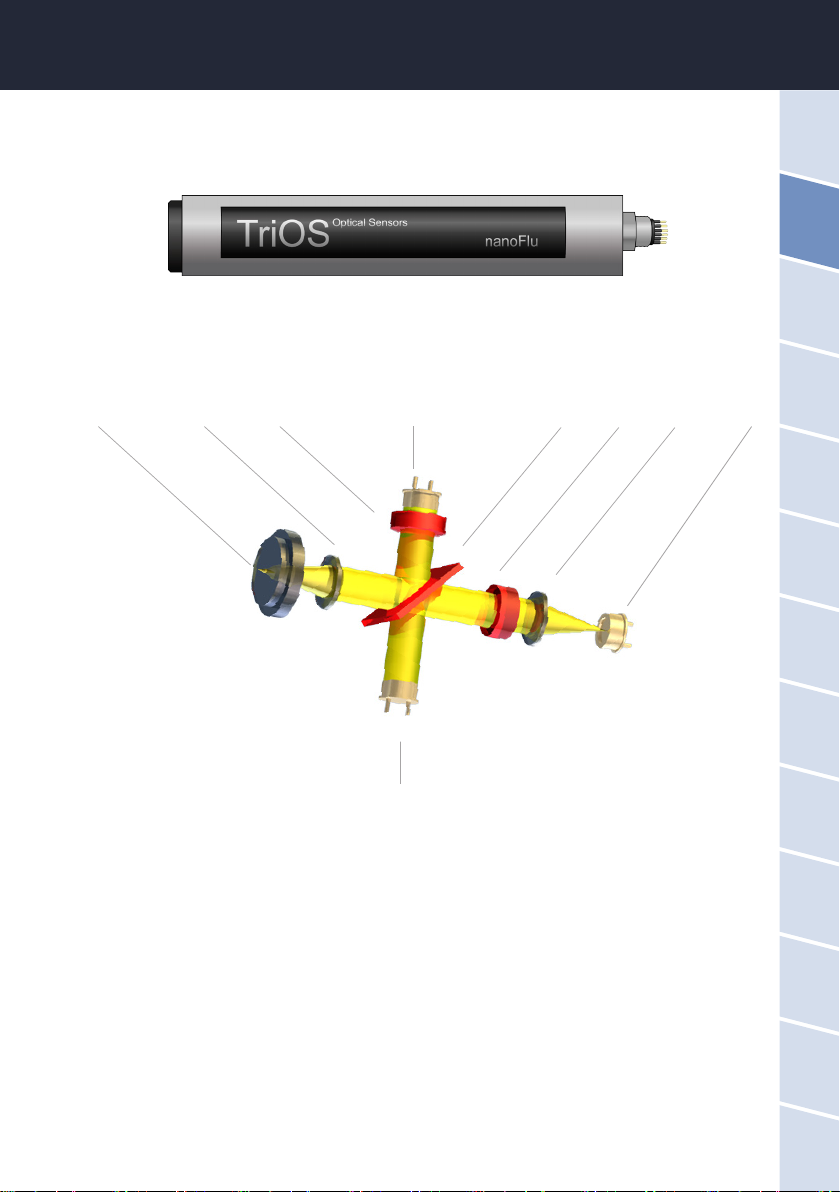
Essentially, the nanoFlu consists of four parts: a dened light source, a lens system, the optical path and a
detector with ambient light suppression. The arrangement of these parts is represented schematically in the
above illustration.
The light source consists of an LED with a dened wavelength depending on the version or parameter.
The excitation light beam is parallelized and a small part is reected by a beam splitter (short pass) onto a ref-
erence diode to compensate uctuations in the light source. A large part of the light is focused with a lens about
10 mm in front of the optical window. Fluorescent light is collected with the same lens and is reected again by
the beam splitter due to the higher wavelength. An interference lter in front of the photodiode for measuring
uorescence intensity prevents extraneous and scattered light from penetrating.
A special electronic circuit is used to eliminate ambient light.
Focal point Lens Filter Photodiode Beam splitter Filter Lens LED
Photodiode

8D01-060en202008 Manual nanoFlu
Use Calibration Malfunction &
Maintenance
Commis-
sioning
General
Information FAQTechnical Data Warranty Customer
Service Contact Keyword
Index
AccessoriesIntroduction
Introduction // nanoFlu
2.3.1 Fluorescence
Fluorescence is the spontaneous emission of light directly after a material has been excited. The emitted light is
generally lower in energy (larger wavelength) than the previously absorbed light (shorter wavelength).
Photons are absorbed and electrons of the molecule are lifted into an energetically higher orbital, i.e. excited. If
they fall back to their original level, the released energy produces heat and photons (uorescent light).
Double-bond electrons are excited more easily, because the p-electrons of the double bond are distributed over
both atoms and are therefore not so strongly bound. Molecules with a conjugated double bond are particularly
suitable for uorescence; the electrons are distributed over several atoms and are therefore very easy to excite.
2.3.2 Parameters
Depending on the parameters, nanoFlu uses dierent LEDs for long-term stable measurements of uorescence
values. The following parameters (see table) can be measured or derived with nanoFlu.
Parameter Excitation wavelength Detection wavelength
Chl-a 470 682
blue 620 655
CDOM 360 460
2.4 Browser
nanoFlu is equipped with a web interface, which can be used to congure the sensor. To access the web inter-
face, you will need the G2 interface box and an Ethernet-capable device with a web browser, e.g. a notebook.
Open one of the following URLs (depending on the network structure) in your web browser:
http://nanoFlu/ or
http:// nanoFlu _D2XX/ (D2XX is the serial number) or
http://192.168.77.1/
When connected to an Internet-capable device, automatic measurements will be stopped. As
soon as the sensor is disconnected from your device, the measurements will continue at the
set interval if the timer is activated for automatic measurements.

9D01-060en202008 Manual nanoFlu
UseCalibration
Malfunction &
Maintenance
Commis-
sioning
General
Information
FAQ Technical DataWarranty
Customer
Service
Contact
Keyword
Index Accessories Introduction
nanoFlu // Introduction
The web interface is divided into three areas (see gure):
Title, menu and contents.
In the menu on the left, the subpoints are listed. There is a “Help” link on the right side that will take you to the
TriOS Mess- und Datentechnik GmbH website. An active Internet connection is required to access the website.
The menu is used to navigate the web interface. Each line is a link to another page with dierent setting options.
The link that refers to the page currently displayed is always highlighted in the menu. Special, selected contents
and functions are exclusively reserved for the employees of TriOS Mess- und Datentechnik GmbH Customer
Service. Authentication is needed for this content.
The “Contents” area displays the relevant information and setting options. Contents that require authentication
are deactivated (“grayed out”).
Menu
Title
Contents
Overview
As shown in the following illustration, basic information about the sensor is summarized on the “Overview”
page. This includes the device type and serial number of the sensor as well as the version number of the in-
stalled rmware, interface and parameters.
10 D01-060en202008 Manual nanoFlu
Use Calibration Malfunction &
Maintenance
Commis-
sioning
General
Information FAQTechnical Data Warranty Customer
Service Contact Keyword
Index
AccessoriesIntroduction
Introduction // nanoFlu
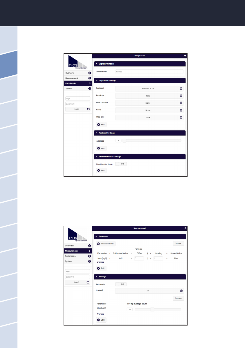
Peripherals
In the environment settings (“Peripherals”), various options are available depending on the version of the sen-
sor.
Measurement
The "Measurement" page shows the results of the last measurement. In addition, the interval settings for the
automatic measurements and the number of individual measurements to be averaged for the nal measure-
ment can be changed here. On this page, it is also possible to scale the measured value with the help of entries
for “Oset” and “Scaling”.
The new measurement can be triggered at any time. To do this, click on the “Measure Now!” button. A new
measurement will then be carried out with the saved settings.

11D01-060en202008 Manual nanoFlu
UseCalibration
Malfunction &
Maintenance
Commis-
sioning
General
Information
FAQ Technical DataWarranty
Customer
Service
Contact
Keyword
Index Accessories Introduction
nanoFlu // Introduction
In order to make changes, the "Edit" button must rst be pressed in the corresponding area.
The parameter can be calculated automatically with a scaling factor and an oset for specic parameters. The
scaling factor always depends on the application and must be determined by the user, with the exception of the
parameters predened by the manufacturer. The values are entered in the corresponding “Scaling” and “Oset”
elds. More information on the scalable parameters can be found in chapter 5.2 - Customer Calibration.
The time interval for automatic measurements is entered in the eld for “Interval”. This interval should be un-
derstood as a minimum value. If the previous measurement has not yet been completed after the interval has
elapsed (e.g. because the nanoFlu simply needs more time to calculate the average), this previous measure-
ment will be waited out before the next one is started.
The factory-set measurement interval recommended by TriOS Mess- und Datentechnik GmbH is 3 seconds.
If several individual measurements are to be averaged for one measurement, the number of measurements
can be set via the controller.
System
The “System” page is used to manage the sensor. On this page you can add a comment under "Description". In
addition, a restore point can be created or uploaded (see chapter 6.2.2) and the system log le can be export-
ed. The sensor no longer has integrated RTC (real time clock) time buering, which is why the date is reset to
01.01.1998 each time it is switched on.
Service
To use the Service function, you need a login and a password. You will receive this when you participate in a
TriOS training session.
Important: Modied values must be saved by clicking on the “Save” button for them to be
used for subsequent measurements.
12 D01-060en202008 Manual nanoFlu
Use Calibration Malfunction &
Maintenance
Introduction
General
Information FAQTechnical Data Warranty Customer
Service Contact Keyword
Index
Accessories
Commis-
sioning
Commissioning // nanoFlu
3 Commissioning
This chapter deals with the commissioning of the sensor. Please pay particular attention to this section and
follow the safety precautions to protect the sensor from damage and yourself from injury.
Before the sensor is put into operation, it is important to ensure that it is securely attached and all connections
are connected correctly.
3.1 Electrical Installation
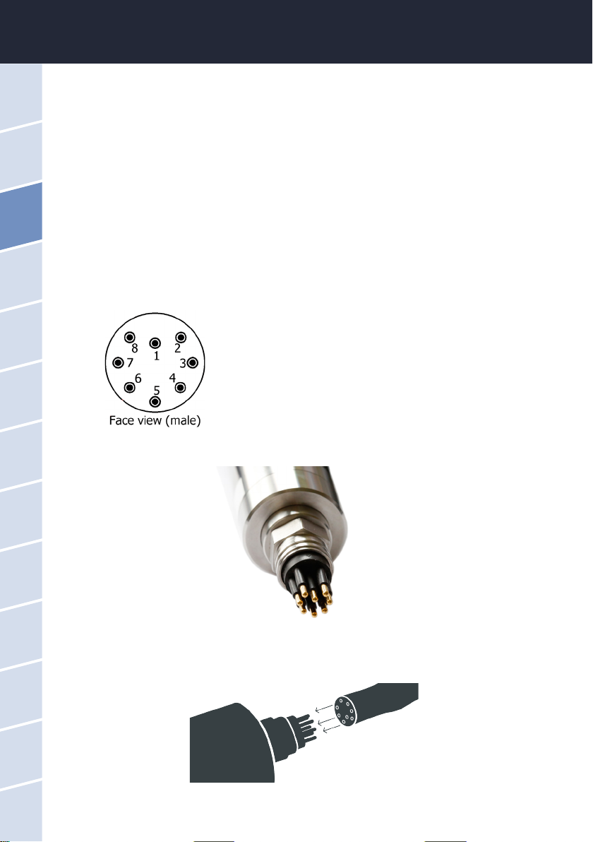
3.1.1 SubConn 8-pin Connector
1. Ground (Power + Ser. Interface)
2. RS232 RX / RS485 A (commands)
3. RS232 TX / RS485 B (data)
4. Power (12...24 VDC)
5. ETH_RX-
6. ETH_TX-
7. ETH_RX+
8. ETH_TX+
Connect the male end of the connecting cable into the connector by making the pins align with the slots of the
cable.

13D01-060en202008 Manual nanoFlu
UseCalibration
Malfunction &
Maintenance Introduction General
Information
FAQ Technical DataWarranty
Customer
Service
Contact
Keyword
Index Accessories Commis-
sioning
nanoFlu // Commissioning
The next step is to hand-tighten the locking sleeve to secure the end of the connector into the bulkhead con-
nection.
3.1.2. Fixed Cable with M12 Industrial Plug
1. RS232 RX / RS485 A (commands)
2. RS232 TX / RS485 B (data)
3. ETH_RX-
4. ETH_RX+
5. ETH_TX-
6. ETH_TX+
7. Ground (Power + Ser. Interface)
8. Power (12...24 VDC)
Do not twist or bend the connector when plugging or unplugging it. Insert the con-
nector straight in and use the locking sleeve to attach the male contact pin.
NOTICE
Ensure correct polarity of the operating voltage, because otherwise the sensor
may be damaged.
NOTICE
14 D01-060en202008 Manual nanoFlu
Use Calibration Malfunction &
Maintenance
Introduction
General
Information FAQTechnical Data Warranty Customer
Service Contact Keyword
Index
Accessories
Commis-
sioning
Commissioning // nanoFlu
• Protocol: Species the data protocol to be used. Supported:
• Modbus RTU
• ASCII Output
3.2 Interfaces
3.2.1 Serial Interface
The nanoFlu provides two lines for digital, serial communication with a control device. It is equipped with a
congurable digital serial interface as RS-232 (also EIA 232) or RS-485 (also EIA 485). The interface cannot be
switched and is already dened when delivered.
For the RS-232, voltages of –15 V to +15 V with respect to the ground are possible. For the RS-485, voltages
of –5 V to +5 V with respect to the ground are possible.
nanoFlu is delivered as RS-485 in the standard version. Upon delivery, the nanoFlu is congured for RS-485
with the following settings:
• Baud rate: 9600 bps
• Data bits: 8
• Stop bits: 1
• Parity: none
Detailed description of the Modbus protocol commands can be found in the annex.
For the RS-232, data transmission takes place on one line per direction, with the RX cable being used for
the communication from the control device to the sensor and the TX cable being used from the sensor to the
control device.
RS-485 uses a dierential signal with the sign-negative potential of the A line is put on the B line. The A-B dier-
ence is decisive, where the transmission is most resistant to interactive interference signals.
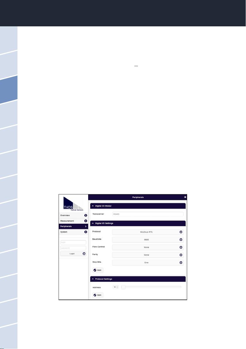
For the nanoFlu, the “Peripherals” page of the web interface allows conguration of the digital interface. The
following setting options are available:
15D01-060en202008 Manual nanoFlu
UseCalibration
Malfunction &
Maintenance Introduction General
Information
FAQ Technical DataWarranty
Customer
Service
Contact
Keyword
Index Accessories Commis-
sioning
nanoFlu // Commissioning
• Baud rate: Species the transmission speed.
• Flow control: Activates ow control on the software level (XON/XOFF).
• Parity: Activates the parity check for data transmission. Possible options are:
• None (deactivated)
• Even
• Odd
• Stop bits: Species the number of stop bits.
In the “Protocol settings” section, you can input settings for the active protocol.
• In the Modbus RTU protocol, the following properties are also available:
• Address: This is the slave address for the Modbus communication. It identies the
sensor in the bus system and must be unique.
3.2.2 Network
For the new TriOS G2 sensors, the IEEE 802.3 10BASE-T-compliant Ethernet interface is used as a universal
interface. This makes it possible to connect a single sensor or even to build a complex sensor network.
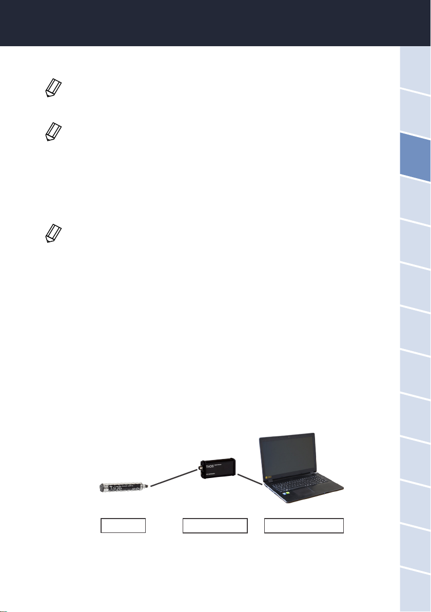
Network with a single G2 sensor
The easiest way to connect to the nanoFlu is with the G2 interface box. It serves as both the connection and the
power supply for the sensor and can be used with all TriOS G2 sensors.
The following gure shows a connection to a single sensor:
The TriOS G2 interface box translates the 8-pin M12 sensor plug to the conventional power supply connections
(2.1 mm barrel connector) and to the network access (RJ45 socket).
G2 sensor G2 interface box Ethernet-capable device
In the event of diculties in the communication, try to reduce the baud rate.
This is only supported with the internal TriOS data protocol and must be deactivated when
using the Modbus RTU.
In various Modbus devices, it may be necessary to set this to “Two” if a parity check does not
need to take place.

16 D01-060en202008 Manual nanoFlu
Use Calibration Malfunction &
Maintenance
Introduction
General
Information FAQTechnical Data Warranty Customer
Service Contact Keyword
Index
Accessories
Commis-
sioning
Commissioning // nanoFlu
2
1
3
G2 interface box
There are three connectors on the housing of the G2 interface box:
1. Power supply 12 or 24 VDC; 2.1 mm barrel connector
2. Sensor connector 8-pin M12
3. Ethernet connection RJ45 socket
Proceed as follows to connect the sensor to an Ethernet-capable device via the G2 interface box:
Step 1) Make sure that the Ethernet adapter of your device is congured to automatically obtain the network
settings (IP address and DNS server).
Step 2) Plug the M12 plug on the cable end of the sensor into the M12 socket (2) of the G2 interface box and
tighten the screw plug.
Step 3) Connect the 12 or 24 VDC power supply to the G2 interface box to supply the sensor with power.
Step 4) Wait at least 3 seconds before you connect your Ethernet LAN cable with your Ethernet-capable device
and the G2 interface box.
The web interface can now be accessed with any browser using the following URLs:
http://nanoFlu/ or
http://nanou_DXXX/ (DXXX is the serial number) or
http://192.168.77.1/
If the web interface cannot be accessed, make sure that the LAN cable was connected after
the sensor was connected to the power supply and try all three URL options.
Automatic measurement by the nanoFlu is stopped when an Ethernet-capable device is
connected. As soon as the LAN connection between the sensor and the Internet capable
device is disconnected, the measurements will be continued at the set interval if the timer is
activated.
17D01-060en202008 Manual nanoFlu
UseCalibration
Malfunction &
Maintenance Introduction General
Information
FAQ Technical DataWarranty
Customer
Service
Contact
Keyword
Index Accessories Commis-
sioning
nanoFlu // Commissioning
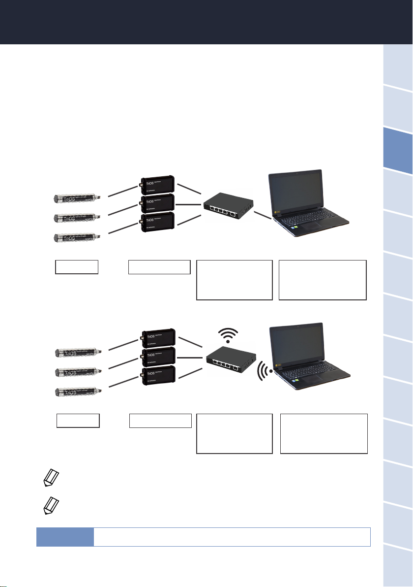
Network with multiple G2 sensors
By using an Ethernet switch / hub or a conventional router, it is possible to connect multiple sensors into a
complex network and use them simultaneously. In the sensor network, each sensor must have its own G2
interface box for power supply.
Like any G2 sensor, the nanoFlu delivers a simple DHCP server as well as a simple DNS server, which is con-
gured exclusively for direct connection, as described in the previous section. For a complex sensor network,
the servers must be supplied by the user. nanoFlu recognizes these automatically and then turns o the internal
servers. Ask your network administrator for advice on how this can best be implemented in your case.
The following illustrations show examples of dierent ways to set up a sensor network.
G2 sensors G2 interface box a) Ethernet-capable device
with DHCP server
b) Ethernet-capable device
a) Ethernet switch / hub
b) Router with DHCP
server
G2 sensors G2 interface box a) Wireless-capable device
with DHCP server
b) Wireless-capable device
a) Access point
b) Wireless router with
DHCP server
If multiple sensors are being used in a network, the web interface can be accessed via the
host name http://nanou_DXXX/ (DXXX is the serial number) or via the IP. Ask your network
administrator for advice.
Damage caused by misuse is not covered by the warranty!
NOTICE
The nanoFlu can only be used by one Ethernet-capable device at one time.
18 D01-060en202008 Manual nanoFlu
Calibration Malfunction &
Maintenance
Commis-
sioning
Introduction
General
Information FAQTechnical Data Warranty Customer
Service Contact Keyword
Index
AccessoriesUse
Use // nanoFlu
4 Use
The nanoFlu can be operated with all TriOS controllers. Instructions for correct installation can be found in the
controller manual.
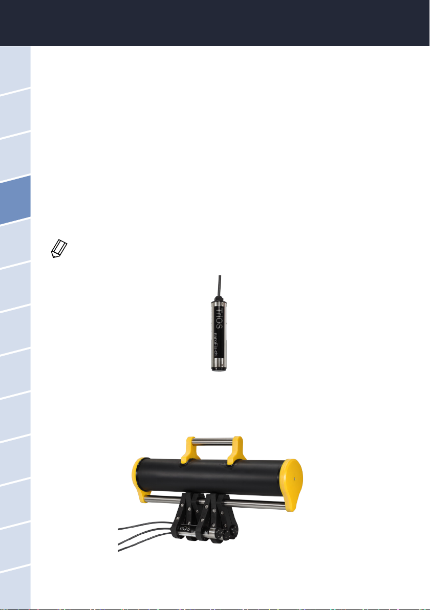
4.1 Normal Operation
4.1.1 Immersion Operation
For immersion operation, the nanoFlu can be completely or partially immersed in the water / measuring me-
dium. To make a correct measurement, the measuring window must be completely immersed and free of air
bubbles. nanoFlu can also be attached with suitable hydraulic clamps. Make sure to use suitable brackets with
an inner diameter of ~36 mm. To protect the housing pipe against excess punctual pressure, install the brackets
close to the device covers. Fitting brackets can be obtained from TriOS.
When immersing the sensor, make sure there are no air bubbles in front of the sensor discs.
If there are air bubbles in front of the window, shake the sensor carefully until the bubbles
have been removed.
4.1.2 Float
nanoFlu can also be used in a oat, which is particularly useful in case of uctuating water levels.
Table of contents
Other triOS Accessories manuals


