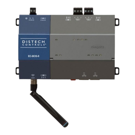
triOS TriBox3 User manual

TriBox3
OPERATING INSTRUCTIONS


1
Product // Chapter
TABLE OF CONTENTS
Table of Contents
1 General Information 2
1.1 Introduction 2
1.2 Health and Safety Information 3
1.3 Warnings 4
1.4 User- and Operating Requirements 4
1.5 Intended Use 4
1.6 Disposal Information 5
1.7 Certicates and Approvals 5
2 Introduction 6
2.1 Product Identication 6
2.2 Scope of Delivery 7
2.3 Product Structure 7
2.4 Control Elements 8
2.4.1 Display 8
2.4.2 Status LED 8
3 Commissioning 9
3.1 Power Supply 9
3.2 Sensor interfaces 9
3.3 Outputs 10
3.4 Menu 10
3.4.1 Main Menu 10
3.4.2 Sensor 11
3.4.3 Display 11
3.4.4 Options 14
3.4.5 Data 17
3.4.6 Info 17
3.4.7 Power and Home 18
4 Use 19
4.1 Mounting 20
4.2 Electrical Installation 23
4.2.1 Operation with AC Voltage 23
4.2.2 Operation with DC Voltage 25
4.2.3 Prioritized Supply Voltage 26
4.3 Connection of the Sensors 27
4.3.1 Moving Average 32
4.3.2 Smoothing 33
4.3.3 Warning Levels 34
4.4 Calibration Wizard 34
4.5 Installation of Compressed Air Flushing 37
4.6 Data Storage 39
4.7 Recovery 41
5 Advanced Use 42
5.1 Data Export 42
5.2 Analog Output 43
5.3 Relay and Buzzer 46
5.4 Modbus RTU 50
5.5 Network 53
5.6 External Trigger 55
6 Malfunction and Maintenance 56
6.1 Cleaning and Upkeep 56
6.1.1 Cleaning the Enclosure 56
6.1.2 Manual Sensor Cleaning 56
6.2 Maintenance and Inspection 56
6.2.1 Service mode 56
6.2.2 Checking the Analog Outputs 57
6.2.3 Checking the Valve 58
6.2.4 Checking the Relay 58
6.2.5 Working on the Compressed Air System 59
6.2.6 Replacing a sensor 59
6.3 Troubleshooting 60
6.3.1 Changing the Fuse 60
6.3.2 Measuring the Output Voltage 62
6.3.3 Sensor is not displayed 63
6.3.4 Calling up the Recovery Point 65
6.3.5 Modbus Server Problems 66
6.3.6 Support Info 67
6.3.7 Software Update 67
6.4 Return 68
7 Technical Data 69
7.1 Technical Specications 69
7.2 External Dimensions 71
8 Accessories 72
8.1 AirShot2 72
8.2 Modbus Distributor Box 72
8.3 Compass 72
8.4 TAMMO / AdamE 72
9 Warranty 73
10 Customer Service 74
11 Contact 75
12 Keyword Index 76
13 FAQ - Frequently Asked Questions 78
Annex 82

2D01-051en202111 Manual TriBox3
Use Advanced
Use Malfunction &
Maintenance
Commis-
sioning
Introduction FAQTechnical Data Warranty Customer
Service Contact Keyword
Index
Accessories
General
Information
General Information // TriBox3
1 General Information
1.1 Introduction
Welcome to TriOS.
Thank you for choosing our TriBox3 controller.
The TriBox3 is a measurement and control unit for all TriOS sensors. The controller has four sensor interfaces, which
support RS-232 and RS-485. In addition to the Modbus RTU, various other protocols are available. A built-in valve
allows the use of compressed air cleaning of the sensors. The TriBox3 also oers a USB connection and the option
of connecting to a network using a wireless or Ethernet interface. There are also six completely congurable outputs
(4...20 mA) available to integrate the TriBox3 into other data acquisition systems. An integrated relay can be used to
trigger alarms or to control external devices. Features such as low power consumption, a robust aluminium housing
and a range of interfaces make these suitable for all applications that have to do with environmental monitoring,
drinking water, wastewater treatment plants and many other areas.
In this manual, you will nd all the information you need to commission and use the TriBox3. You can nd the
technical specications and the dimensions in Chapter 7.
Please note that the user is responsible for complying with local and national regulations on the installation of
electronic devices. Any damage caused by incorrect use or unprofessional installation will not be covered by
the warranty. All sensors and accessories supplied by TriOS Mess- und Datentechnik GmbH must be installed
and operated in accordance with the specications provided by TriOS Mess- und Datentechnik GmbH. All parts
were designed and tested in accordance with international standards on electronic instruments. The device
meets the requirements of the international standards on electromagnetic compatibility. Please use only original
TriOS accessories and cables to ensure smooth and professional operation of the devices.
Please read this manual carefully before using the device and keep this manual on hand for future use. Before
commissioning the controller, please make sure that you have read and understood the following safety pre-
cautions. Always make sure that the controller is correctly operated. The safety precautions described on the
following pages should ensure the smooth and correct operation of the device and any additional associated
devices and should prevent injuries to yourself or other persons and damage to other equipment.
Copyright Notice
All content in this manual, i.e. texts, photographs and graphics, are protected by copyright. Unless expressly
stated otherwise, TriOS Mess- und Datentechnik GmbH is the owner of the copyright. Persons who violate the
copyright shall be liable pursuant to § 106 et seq of the copyright law, they will be warned at their own expense
and must pay compensation.
Software Updates
This manual refers to software version 1.5.4. From time to time TriOS Mess- und Datentechnik GmbH publishes
software updates for the TriBox3. These updates include bug xes, new features and options.
If the translation is at all dierent from the original German text, the German ver-
sion is binding.
NOTICE

3D01-051en202111 Manual TriBox3
Use
Advanced
Use
Malfunction &
Maintenance Commis-
sioning IntroductionFAQ Technical DataWarranty
Customer
Service
Contact
Keyword
Index Accessories General
Information
TriBox3 // General Information
Tip / Useful Information
Can result in damage to property
Warning / may lead to serious injury or death
Caution / may cause moderate injury
Danger warning / will lead to serious injury or death
DANGER
WARNING
CAUTION
NOTICE
1.2 Health and Safety Information
This manual contains important information about health and safety rules. This information is labelled according
to the international specications of ANSI Z535.6 (“Product safety information in product manuals, instructions
and other collateral materials”) and must be strictly followed. The distinction is made between the following
categories:
Electromagnetic Waves
Devices that radiate strong electromagnetic waves can inuence the measurement data or result in a malfunc-
tion of the sensor. Avoid using the following devices in the same room as the TriOS sensors: mobile phones,
cordless phones, transmitters/ receivers and other electrical devices that produce electromagnetic waves.
General warning sign, Follow all safety instructions associated with this symbol to avoid
injury. When attached to the unit, refer to the operating or safety information in the manual.
Warning, possibility of electric shock
This symbol indicates that the marked part must be connected to a protective earth conduc-
tor. If the instrument does not have a mains plug on a cable, connect the protective earth to
the protective earth terminal.
Electrical appliances marked with this symbol must not be disposed of in the normal public
waste system. Return old appliances to the manufacturer. The manufacturer will dispose of
the appliances at no cost to the user.
Warning symbols

4D01-051en202111 Manual TriBox3
Use Advanced
Use Malfunction &
Maintenance
Commis-
sioning
Introduction FAQTechnical Data Warranty Customer
Service Contact Keyword
Index
Accessories
General
Information
General Information // TriBox3
1.3 Warnings
• Make sure never to put damaged products into operation. After receiving the package, examine the de-
vice for any damage due to transport.
• Read the operating instructions carefully before beginning any installation or maintenance work.
• Make sure that the mains power cable is not damaged. Make sure that no heavy objects are placed on
the mains power cable and that the cable is not kinked. Make sure that the mains power cable is not run
near hot surfaces.
• If the cable is damaged, it must be replaced with an original part by the customer service of TriOS Mess-
und Datentechnik GmbH.
• Stop operation of the sensor in the event of excessive heat development (i.e. if it is hot to the touch).
Switch o the controller immediately and unplug the mains power cable from the power supply. Please
contact your dealer or the TriOS customer service.
• Never try to disassemble or modify a part of the controller if such a procedure is not explicitly described in
this manual. Inspections, modications and repairs may only be carried out by the dealer or by qualied
experts authorized by TriOS.
• Devices from TriOS Mess- und Datentechnik GmbH meet the highest safety standards. Repairs to the
device must be carried out by TriOS Mess- und Datentechnik GmbH or by a workshop authorized by
TriOS. Faulty, improper repairs can result in accidents and injuries.
1.4 User and Operating Requirements
The TriBox3 has been developed for use in industry and science. The target group for the operation of the
controller is technically skilled sta in plants, sewage treatment plants, water plants and institutes. We assume
that the personnel are suciently qualied for operation and installation based on their professional training and
experience. The personnel must be able to correctly understand and implement the safety labels and informa-
tion on the packaging and in the package inserts.
1.5 Intended Use
The TriBox3 is intended to control supported sensors and collect, process and store measurement data. Its use
is described in this manual. Please note the technical data of the controller. Any other use is not considered to
be in compliance with the intended use.
According to current scientic knowledge, the device is safe to use when it is handled according to the instruc-
tions in this user manual.
TriOS does not guarantee the plausibility of the measured values. The user
is always responsible for the monitoring and interpretation of the measured
values.
DANGER

5D01-051en202111 Manual TriBox3
Use
Advanced
Use
Malfunction &
Maintenance Commis-
sioning IntroductionFAQ Technical DataWarranty
Customer
Service
Contact
Keyword
Index Accessories General
Information
TriBox3 // General Information
1.6 Disposal Information
At the end of the device’s life or use, the device and its accessories can be returned to the manufacturer for
environmentally friendly disposal (see address below). Please contact us for more details before you send the
device back.
Address of manufacturer:
TriOS Mess- und Datentechnik GmbH
Bürgermeister-Brötje-Str. 25
D-26180 Rastede
Germany
Telephone: +49 (0) 4402 69670 - 0
Fax: +49 (0) 4402 69670 – 20
1.7 Certicates and Approvals
This product meets all the requirements of the harmonized European standards. It therefore meets the legal
requirements of the EU guidelines. TriOS Mess- und Datentechnik GmbH conrms the successful testing of the
product by axing the CE marking (see annex).

6D01-051en202111 Manual TriBox3
Use Advanced
Use Malfunction &
Maintenance
Commis-
sioning
General
Information FAQTechnical Data Warranty Customer
Service Contact Keyword
Index
AccessoriesIntroduction
Introduction // TriBox3
2 Introduction
The TriBox3 is a stationary measurement and control unit for all sensors made by TriOS Mess- und Datentech-
nik GmbH and for select sensors made by other manufacturers.
The system supplies power to the sensors and stores all measurement values, which can be displayed in var-
ious types of representations (numerical or graphical output). In addition, the TriBox3 assumes control of the
entire measurement process as well as monitoring the measurement values.
A potential-free relay output (changeover contact) can be used for external control tasks. The relay switches
when a freely denable limit of a measurement parameter is exceeded or falls short, and an alarm or external
devices, such as pumps, etc., can be controlled.
A compressed air system can be installed to clean the optical sensors. For this purpose, a compressed air valve
is installed in the TriBox3 that can switch in adjustable intervals and thus trigger compressed air cleaning in
combination with a compressed air source.
In combination with the nano-coated glass panes in most optical sensors made by TriOS Mess- und Datentech-
nik GmbH, this makes for a very eective antifouling strategy.
Protection against water jets (IP65) allows operation in moist environments and extends the area of use when
properly installed.
The measurement values are shown on a large TFT color display (resolution of 800x480 pixels) and saved
internally on an SD card. The measurement values that are saved can be exported with a USB stick and then
processed in a spreadsheet.
For wireless data transfer (measurement data, calibration les and service settings), the TriBox3 can be
equipped with a WiFi module.
Six integrated analog outputs (4...20mA) allow the TriBox3 to be integrated into an SPS or other control system.
The device is operated via a capacitive touch screen which lets the user navigate the menu structure. The user
can adjust all settings right on the device.
2.1 Product Identication
The TriBox3 is available in three versions: with 4-digit serial number with and without WiFi and with 8-digit serial
number, especially for the EGC Water Analyzer.
There is a rating plate on the product with the following information that you can use to uniquely identify the
product:
Serial number
Product type
Power supply

7D01-051en202111 Manual TriBox3
Use
Advanced
Use
Malfunction &
Maintenance Commis-
sioning General
Information
FAQ Technical DataWarranty
Customer
Service
Contact
Keyword
Index Accessories Introduction
TriBox3 // Introduction
2.2 Scope of Delivery
The delivery contains the following components:
• TriBox3 with installed mains power cable and Schuko plug for operation in dry rooms
• Operating Instructions
• Accessories (if applicable)
In addition to the product bar code, the rating plate includes the TriOS Mess- und Datentechnik GmbH logo and
the quality label.
Please note that the specications given here are for illustration purposes only and may deviate depending on
the version of the product.
2.3 Product Structure
The following gure shows the main interfaces of the TriBox3.
Touch-display
USB
Compressed air
input
Ethernet
Compressed air
output
Sensor connec-
tions
Cable bushing
for relay
Cable bushing
for AC supply
Cable bushing
for DC supply
Analog outputs
External trigger
LED display
Keep the original packaging of the device in case it needs to be returned for maintenance or
repairs.

8D01-051en202111 Manual TriBox3
Use Advanced
Use Malfunction &
Maintenance
Commis-
sioning
General
Information FAQTechnical Data Warranty Customer
Service Contact Keyword
Index
AccessoriesIntroduction
Introduction // TriBox3
2.4 Control Elements
2.4.1 Display
The TriBox3 has a capacitive touch-display with a resolution of 800x480 pixels. The display is not controlled
by pressure, rather by touch or light tapping. It can be operated with bare ngers or with a special touch pen.
The main screen as well as the xed control elements to the right and above can be congured individually.
The measurement values/spectra and the device conguration of the TriBox3 can be represented by the user
using dierent displays. With the touch screen, the various displays can be selected by “swiping” or touching.
Navigation bar
Individually congurable
display area
Menu page
Display of available
pages
2.4.2 Status LED
ashing in service mode
active power supply for the sensor (see chapter 3.4.4)
measurement active
cleaning active
The use of sharp or pointed objects when operating the touch-display can cause
damage to the display.
NOTICE

9D01-051en202111 Manual TriBox3
Use
Advanced
Use
Malfunction &
Maintenance General
Information
FAQ Technical DataWarranty
Customer
Service
Contact
Keyword
Index Accessories Commis-
sioning Introduction
TriBox3 // Commissioning
3 Commissioning
This chapter deals with the commissioning of the controller up to the rst function test. Please pay particular
attention to this section and follow the safety precautions to protect the product from damage and yourself from
injury.
Before the sensor is put into operation, it is important to ensure that all connections are connected correctly.
3.1 Power Supply
Plug the provided power supply cable into a Schuko socket that has been professionally installed. To protect
against overloading, the device has internal glass tube fuses.
3.2 Sensor interfaces
The Tribox3 uses the following fuses:
Fuse F1 1A, 250 V, time-lag, 5x20mm; item no. 00P100009
Fuse F2 and F3 4A, 125 V, fast-blow, SMD without holder; item no. 00P100008
Fuse F4 to F14 1A, 125 V, fast-blow, SMD without holder; item no. 00P100007
The TriBox3 requires a secure power supply within the voltage range of 100 VAC to 240 VAC with a mains
frequency of 50 Hz to 60 Hz. The power supply must be secured according to the local safety standards.
The TriBox3 is shipped with a mains power cable that can be replaced by an alternative customer-specic
cable if necessary (see chapter 4.2.1). The Tribox3 can also be powered by 12 ‒ 24 VDC (see chapter 4.2.2).
The TriBox3 is equipped with four female M12 sensor interfaces. The interfaces support RS-232 and RS-485
and can be set for the serial TriOS protocol, Modbus RTU and other special protocols.
The device has a housing grounding (protective conductor), which must be
connected to the ground potential when operating with low voltage. Protec-
tive conductor grounding is recommended when operating with 12 ‒24 VDC.
DANGER
If you need to replace a defective fuse, rst unplug the power supply and use
only fuses of the same type. Make sure you have completely eliminated the
error before putting the device back into operation.
DANGER
Danger to life due to electric shock. A residual current circuit breaker with a
maximum ignition current of 30 mA must be used. A surge protector should
be used for outdoor installations.
DANGER

10 D01-051en202111 Manual TriBox3
Use Advanced
Use Malfunction &
Maintenance
Introduction
General
Information FAQTechnical Data Warranty Customer
Service Contact Keyword
Index
Accessories
Commis-
sioning
Commissioning // TriBox3
3.3 Outputs
The TriBox3 has six analog outputs. The four cable glands at the bottom left of the image are not normally
assigned, whereas the lower right cable bushing is intended for the mains power cable and therefore also has
a larger cross section. When delivered, the mains power cable is already installed at this location. The upper
right cable bushing is intended for the relay.
1. RS-232 TX / RS-485 A
2. RS-232 RX / RS-485 B
3. not connected
4. not connected
5. not connected
6. +12 VDC
7. GROUND
8. +24 VDC
3.4 Menu
After installation, the TriBox3 can be switched on by switching on the power supply.
3.4.1 Main Menu
The main menu can be seen in the navigation bar on the right side of the display. This is always visible regard-
less of the submenu currently displayed, so that the user can switch between menu items at any time.
Sensors and COM ports Display and settings
Display conguration
System settings
Export and import of data
Device information and support contact
Switch o display or restart TriBox3
M-12 industrial plug
Cable bushing for relay
Cable bushing for analog outputs and triggers
The designations of the data lines can be seen from the TriBox3. For example, RS-232 RX is
the receiving line and RS-232 TX is the transmission line of the TriBox3.

11D01-051en202111 Manual TriBox3
Use
Advanced
Use
Malfunction &
Maintenance Introduction General
Information
FAQ Technical DataWarranty
Customer
Service
Contact
Keyword
Index Accessories Commis-
sioning
TriBox3 // Commissioning
3.4.2 Sensor
The “Sensor” button opens a submenu that displays the four COM ports, with sensors if applica-
ble. If there are no sensors connected or if they are not recognized by the TriBox3, the “Sensor”
submenu displays the following:
If a sensor is connected and is not shown on a COM port, a device search of all COM ports is initiated by press-
ing on the “Scan for Sensors” button in the lower area of the “Sensor” submenu.
If a connected sensor is not displayed after scanning the COM ports, check the compatibility of the sensor and
COM port settings (see chapter 4.3 and 6.3.3).
3.4.3 Display
The “Display” button opens a submenu that shows displays which are already congured and
allows reconguration. It also allows the creation and conguration of new displays.

12 D01-051en202111 Manual TriBox3
Use Advanced
Use Malfunction &
Maintenance
Introduction
General
Information FAQTechnical Data Warranty Customer
Service Contact Keyword
Index
Accessories
Commis-
sioning
Commissioning // TriBox3
Change the position of a selected display in the entire order.
For example, select “Sample values” and then press the arrow up to move this display in the entire order.
Create new display.
1. Select a page layout from the options displayed.
“Sample values” is already available when commissioning the device.
2. Click on any eld of the selected page layout.

13D01-051en202111 Manual TriBox3
Use
Advanced
Use
Malfunction &
Maintenance Introduction General
Information
FAQ Technical DataWarranty
Customer
Service
Contact
Keyword
Index Accessories Commis-
sioning
TriBox3 // Commissioning
current value current measurement value as a number (scaled value)
time variation curve representation of the measurement value over time
spectrum for spectral probes, representation of the measurement value over the wavelength
3. Select what is to be displayed: the current value, the values over a certain period of time as a hydrograph
or a spectrum.
4. Select the sensor and the parameter and conrm by clicking “OK”.

14 D01-051en202111 Manual TriBox3
Use Advanced
Use Malfunction &
Maintenance
Introduction
General
Information FAQTechnical Data Warranty Customer
Service Contact Keyword
Index
Accessories
Commis-
sioning
Commissioning // TriBox3
Rename the selected display.
Delete the selected display.
5. The selected parameter of the selected sensor will be displayed in the selected window.
3.4.4 Options
The “Options” button opens a submenu that allows you to set general settings, dene measure-
ment and cleaning intervals, control the relay and buzzer and congure the analog outputs.
Service Mode
By pressing the “Service mode” button, the TriBox3 can be put into a paused state. As long as the service mode
is active, all measured values and analog outputs are held at the last measured value to avoid malfunction
alarms when cleaning, etc. Automatic communication with the sensor no longer takes place (cleaning, relays,
valves, etc.). Please refer to chapter 6.2.1.

15D01-051en202111 Manual TriBox3
Use
Advanced
Use
Malfunction &
Maintenance Introduction General
Information
FAQ Technical DataWarranty
Customer
Service
Contact
Keyword
Index Accessories Commis-
sioning
TriBox3 // Commissioning
General settings
In the subitem “General settings”, language, system time and password can be set.
Network settings
Subitem “Network settings” is dealt with in chapter 5.5.
Automatic measurements
The subitem “Automatic measurements” allows conguration of the automatic measurements.
To make use of an automatic measurement interval, this must rst be activated by checking the box and setting
a measurement interval. For automatic measurement, the sensor must also be activated for automatic meas-
urement (see chapter 4.3).
The power on the COM port can also be switched o after each measurement to save energy and individual
measurements can be triggered. If this function is activated, the middle LED in the sensor power supply lights
up.
In the subitem “General settings”, language and system time can be set. The system must be
restarted after selecting the language.

16 D01-051en202111 Manual TriBox3
Use Advanced
Use Malfunction &
Maintenance
Introduction
General
Information FAQTechnical Data Warranty Customer
Service Contact Keyword
Index
Accessories
Commis-
sioning
Commissioning // TriBox3
Cleaning
The subitem “Cleaning” allows the user to dene the cleaning intervals.
Relay control
The subitem “Relay control” is dealt with in chapter 5.3.
Buzzer control
The subitem “Buzzer control” is dealt with in chapter 5.3.
Analog outputs
The subitem “Analog outputs” is dealt with in chapter 5.2.
Modbus server settings
The TCP/IP port and the slave address of the Tribox can be changed under “Modbus server settings”. Detailed
information on the use of the Modbus server mode can be found in chapter 5.4.

17D01-051en202111 Manual TriBox3
Use
Advanced
Use
Malfunction &
Maintenance Introduction General
Information
FAQ Technical DataWarranty
Customer
Service
Contact
Keyword
Index Accessories Commis-
sioning
TriBox3 // Commissioning
3.4.5 Data
For more information on the menu item “Data”, please see chapter 5.1.
3.4.6 Info
The “Info” button opens a window with system information, messages and the contact data of the
nearest contact in case of problems or general inquiries. Before contacting the contact person,
please read chapter 6 to ensure you have the right information for ecient troubleshooting.

18 D01-051en202111 Manual TriBox3
Use Advanced
Use Malfunction &
Maintenance
Introduction
General
Information FAQTechnical Data Warranty Customer
Service Contact Keyword
Index
Accessories
Commis-
sioning
Commissioning // TriBox3
3.4.7 Power and Home
The “Power” button opens a window to restart the TriBox3 or switch o the display (e.g. to save
energy in an autonomous measuring station). When the display is o, you can turn it back on by
touching the screen again.
The “Home” button is only visible as long as the conguration menus are open. By pressing this
button, the conguration menus are closed and only the displays are still visible.
The “System Info” menu appears automatically when the menu item “Info” is opened.
Here you can nd information such as the serial number, storage space, etc.
Under “Message log”, you will nd program messages that are only relevant when
contacting support.
Under “Contact”, you will nd the contact information of the manufacturer.
To make sure that all previously entered settings are saved and updated, the controller
should be restarted after every reconguration. After the restart, a recovery point should be
stored.
Table of contents
Popular Controllers manuals by other brands
Norac
Norac UC5 Topcon X30 installation manual
Franklin Electric
Franklin Electric SubDrive75 installation manual
ez-wheel
ez-wheel SWD Starter Kit instruction manual

Exalux
Exalux Control One user manual
EINHELL
EINHELL ESS 9000-T Assembly and operating instructions
Siemens
Siemens LME39 Series Basic documentation

