triple solar M2 360 200 landscape User manual

manual
heat pump panels
triple solar
heating without gas
versie 9-03-2020
S
t
a
n
Index
1. General information........................................................................................ 2
Safety instructions ........................................................................................ 2
Legal requirements, standards and regulations ................................................. 2
Permitted load of the panels........................................................................... 2
Transport reguations ..................................................................................... 2
2. Technical information ..................................................................................... 3
Measures ..................................................................................................... 3
Size, weight and material .............................................................................. 4
3. Placement of the panel field ........................................................................... 4
Inclination angle on flat roof........................................................................... 4
Space between rows on flat roof ..................................................................... 4
4. Assembly parts ............................................................................................... 5
Standard components ................................................................................... 5
Pitched roof mounting parts, tiled roof............................................................. 6
Flat roof mounting parts ................................................................................ 6
Hydraulic, electrical and other components ...................................................... 7
5. Preparation for pitched roof, tiled roof ........................................................... 8
Aligning panels and installing roof brackets ...................................................... 8
6. Preparation for a flat roof ............................................................................. 12
7. Installation of the panels.............................................................................. 13
Placing the TS clamping profile ......................................................................13
Mounting of the panels .................................................................................14
Mounting the TS clamping profile ...................................................................16
Mounting connecting hoses and/or connection plugs ........................................17
Connecting the PV panels electrically..............................................................17
8. Connecting the pipes .................................................................................... 19
Material and position ....................................................................................19
Fittings .......................................................................................................20
Pipe diameters of source pipes ......................................................................22
Hydraulic plan .............................................................................................22
Filling medium.............................................................................................23
Installing the expansion vessel ......................................................................23
Connecting thermostatic mixing valve ............................................................23
Insulation ...................................................................................................24
Micro air bubble separator ............................................................................24
9. Finishing a pitched roof ................................................................................ 25
10. Activating the system ................................................................................. 26
Testing leak tightness, filling and system pressure .........................................26
Commissioning the heat pump (IBS) ............................................................27
11. Maintenance ............................................................................................... 28
12. Warranty conditions ................................................................................... 28

2
Triple Solar assembly instruction PVT heat pump panels March 2020
1. General information
Safety instructions
Your basic equipment should consist of at least:
-safety shoes
- helmet
- safety goggles
- cut-resistant gloves
Attach ladders at an angle of 65 - 75 ° only to safe supports and also secure them against sinking,
slipping or falling over. Use ladders only to bridge a maximum difference in height of 5m. Do not use
damaged or repaired ladders. The ladder must protrude 1 metre above the roof edge.
In the traffic zone, secure the site with barriers, especially below the installation location.
Use impact or fall protection on the roof or ropes with harnesses attached to a fixed anchor point.
Electrical wires that can be touched by heat pump panels must be disconnected or covered by the
responsible electricity company.
Necessary safety distances from power cables to the worker's working area:
- safety beam 1 m to 1 kV voltage
- safety beam 3 m to 110 kV voltage
- safety beam 4 m to 220 kV voltage
- safety beam 5 m to 380 kV voltage
Note the large wind surface area of heat pump panels and accessories. Provide a stable surface during
installation. Stop the installation in case of strong gusts of wind.
Provide lightning protection during assembly in accordance with building regulations.
Legal requirements, standards and regulations
The installation must comply with local conditions, local regulations and, last but not least, technical
rules.
The relevant safety regulations (e.g. NEN1010) must be observed.
The mounting material supplied by Triple Solar is TÜV approved and in accordance with Eurocode EN
1991-1-4. Manufacturer's instructions must be observed in order to make a warranty claim.
Permitted load of the panels
The heat pump panels are designed for the following permitted loads:
- Pressure load (Snow, Wind): 5400 Pa
- Tensile load (Wind): 2400 Pa
When using third-party mounting systems, these values must be observed.
When using the mounting materials supplied by Triple Solar, the above values apply.
Transport reguations
The heat pump panels may only be supported on the frame via the profiles on the short side of the
panel.
The hydraulic connections as well as the collection tubes and fin packages may not be used to lift the
heat pump panel. Aids such as lifting straps, etc. may not be attached to the pipes.
As long as the heat pump panels are stored, the caps remain on the connections to prevent dirt from
getting into the pipes.

3
Triple Solar assembly instruction PVT heat pump panels March 2020
2. Technical information
Measures
Model: M2 360 200 landscape
Model: M2 300 165 landscape
Figure 2.1-a heat pump panel type M2 360 200 landscape
Figure 2.1-b heat pump panel type M2 300 200 landscape

4
Triple Solar assembly instruction PVT heat pump panels March 2020
Size, weight and material
size
unity
M2 360 200
landscape
M2 300 165
landscape
Outside dimensions
mm
1987 x 995
1668 x 995
Height
mm
65
65
PV size
mm
1945 x 984
1648 x 984
Weight (empty / full)
kg
28 / 32
23 / 27
PV power
Wp
360
300
Gross surface
m2
1,98
1,65
materials
PV-panel
Glass
Heat exchanger tubes
Copper
Heat exchanger fins
Aluminium
Finishing
Kataforese
3. Placement of the panel field
Inclination angle on flat roof
Mount heat pump panels at an angle between 10° and 30°.
(Areas with a lot of snow: install the heat pump panels at an angle between 30° and 90°)
Space between rows on flat roof
The greater the row spacing, the less shadow there is. For the electrical output of the installation it is
important to have as little shading as possible, see figure 3.2-a.
5
Triple Solar assembly instruction PVT heat pump panels March 2020
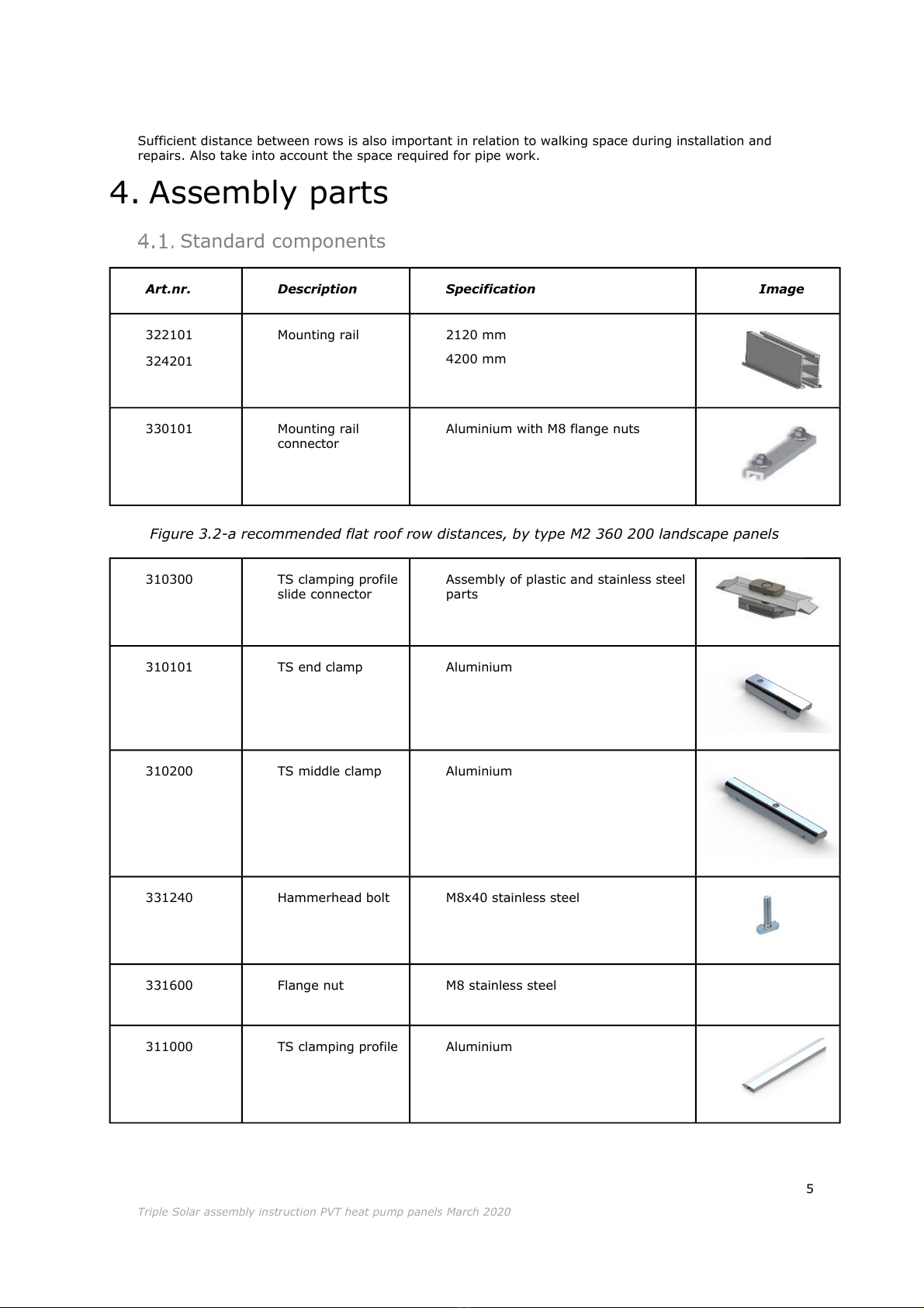
Sufficient distance between rows is also important in relation to walking space during installation and
repairs. Also take into account the space required for pipe work.
4. Assembly parts
Standard components
Art.nr.
Description
Specification
Image
322101
324201
Mounting rail
2120 mm
4200 mm
330101
Mounting rail
connector
Aluminium with M8 flange nuts
310300
TS clamping profile
slide connector
Assembly of plastic and stainless steel
parts
310101
TS end clamp
Aluminium
310200
TS middle clamp
Aluminium
331240
Hammerhead bolt
M8x40 stainless steel
331600
Flange nut
M8 stainless steel
311000
TS clamping profile
Aluminium
Figure 3.2-a recommended flat roof row distances, by type M2 360 200 landscape panels

6
Triple Solar assembly instruction PVT heat pump panels March 2020
410500
TS retaining clip
Stainless steel
(for connecting plugs and end plugs)
Pitched roof mounting parts, tiled roof
Additional components required for pitched roof installation
Art.nr
Description
Specification
Aantal
Image
300231
Roof bracket with foot
Multi-adjustable, incl.
cross-connector
4x per panel
336200
Screw
7,0x50 stainless steel
(TX30)
2x per roof bracket
Flat roof mounting parts
Additional components required for flat roof installation:
Art.nr
Description
Specification
Aantal
Image
300510
Flat roof frames first
panel south, per row
Sunbeam Universal
1x per panel
Zie figure 4.3-a
300520
Flat roof frames
supplementary panel
south, per row
Sunbeam Universal
1x per panel
-
300530
Flat roof frames first
panel east/west, per
row
Sunbeam Symmetrical
1x per panel
-
300540
Flat roof frames
supplementary panel
east/west, per row
Sunbeam Symmetrical
1x per panel
-
330250
Cross connector
Aluminium
For fastening mounting
rail on Sunbeam flat
roof frames
4x per #300510
2x per #300520
4x per #300530
2x per #300540
Figure 4.3-a Sunbeam frame for flat roof

7
Triple Solar assembly instruction PVT heat pump panels March 2020
Hydraulic, electrical and other components
430010
Valve
3/4" inside/outside
500000
Thermostatic
mixing valve
1” outside DN25
500200
Flush and fill
connection set
1” inside DN25
500100
Expansion vessel
18 L
500150
Expansion vessel
connection group
Including automatic air vent, pressure
gauge and pressure relief valve 3 bar
800010
TS crane grease
25 gram
610015
PV cable
0,4 meter
411000
TS connecting hose
Stainless steel, with double o-ring
410300
TS connection plug
¾” outside with double o-ring
410200
TS end plug with
air vent
With double o-ring

8
Triple Solar assembly instruction PVT heat pump panels March 2020
5. Preparation for pitched roof, tiled roof
Attention:
See also the Wagner assembly instruction film on the Triple Solar website.
Aligning panels and installing roof brackets
Each panel is supported by two horizontal mounting rails. These are positioned parallel to each other,
see figure 5.1-a. It is recommended to plan the configuration of panels, pipes and hoses before starting
the installation.
Four roof brackets are required per panel. 2 Screws are included per roof bracket; 7,0x50 stainless steel
Attention:
The dimensions in figure 5.1-a are critical. If they are not respected, the warranty on the panels
will be invalid.
•Start with the lower rail of the lower row of panels. Place the outermost roof bracket at 450 mm
from the edge of the panel field. Spread the rest of the roof brackets evenly with 1000 mm
distance between them. Maximum distance is 1600mm depending on the size of the field, see
figure 5.1-b.
Figure 5.1-a sloping roof alignment diagram (dimensions in mm) The lengths can differ per type of panel.

9
Triple Solar assembly instruction PVT heat pump panels March 2020
Figure 5.1-b Pitched roof alignment diagram (dimensions in mm) The lengths can differ per
type of panel.
•Attach the roof brackets if necessary with extra underlayment wood to get the correct height
and/or for a more solid mounting.

10
Triple Solar assembly instruction PVT heat pump panels March 2020
Figure 5.1-c Pitched roof mounting instruction roof brackets (dimensions in mm)
•Place the first mounting rail on the roof brackets and slide the cross connector into the groove
on the side of the mounting rail. Tighten the mounting rail by tightening the flange nut of the
cross connector to 26Nm (drive SW13). See also figure 5.1-d as an example.
•If more than one rail is to be connected, insert the mounting rail connector into the next rail
and repeat step 4.
•For the next row, consider the vertical distance between the rows of heat pump panels.
Distance between panels at least 40mm.
•With some roof tiles it is necessary to slightly grind the tiles at the bottom as a recess for the
roof brackets.
11
Triple Solar assembly instruction PVT heat pump panels March 2020
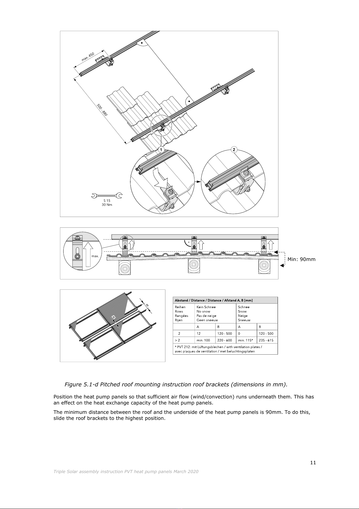
Min: 90mm
Position the heat pump panels so that sufficient air flow (wind/convection) runs underneath them. This has
an effect on the heat exchange capacity of the heat pump panels.
The minimum distance between the roof and the underside of the heat pump panels is 90mm. To do this,
slide the roof brackets to the highest position.
Figure 5.1-d Pitched roof mounting instruction roof brackets (dimensions in mm).
12
Triple Solar assembly instruction PVT heat pump panels March 2020
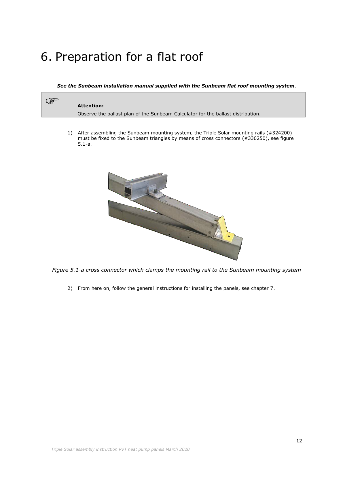
6. Preparation for a flat roof
See the Sunbeam installation manual supplied with the Sunbeam flat roof mounting system.
Attention:
Observe the ballast plan of the Sunbeam Calculator for the ballast distribution.
1) After assembling the Sunbeam mounting system, the Triple Solar mounting rails (#324200)
must be fixed to the Sunbeam triangles by means of cross connectors (#330250), see figure
5.1-a.
Figure 5.1-a cross connector which clamps the mounting rail to the Sunbeam mounting system
2) From here on, follow the general instructions for installing the panels, see chapter 7.

13
Triple Solar assembly instruction PVT heat pump panels March 2020
7. Installation of the panels
Placing the TS clamping profile
The TS clamping profile must be prepared on the mounting rails before the heat pump panels are laid on
them. The TS clamping profile is mounted in the middle behind the heat pump panel and is only pushed
into place over the panel profile after the panels have been installed. The panel profile is located at the
back side of the heat pump panels. This TS clamping profile is required due to wind and tensile loads at
the centre of the heat pump panel. (The aluminium frame that surrounds PV panels and provides this
rigidity is missing in the heat pump panels).
•Insert the clamping profile connector into the rail and turn it a quarter turn.
•Slide the TS clamping profile over the connector. Make sure it is placed in the right direction to fit later in
the panel profile.
Figure 7.1-a –Insert TS clamping profile slide connector into the mounting rail
Figure 7.1-b sliding the TS clamping profile over the TS clamping profile slide
connector
14
Triple Solar assembly instruction PVT heat pump panels March 2020
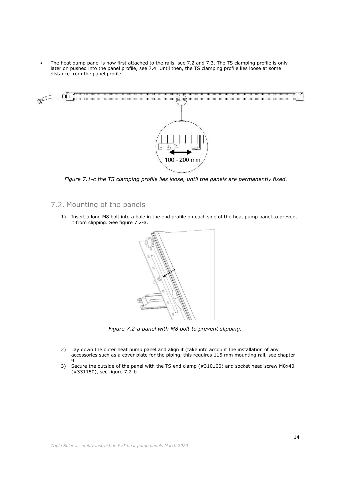
•The heat pump panel is now first attached to the rails, see 7.2 and 7.3. The TS clamping profile is only
later on pushed into the panel profile, see 7.4. Until then, the TS clamping profile lies loose at some
distance from the panel profile.
Mounting of the panels
1) Insert a long M8 bolt into a hole in the end profile on each side of the heat pump panel to prevent
it from slipping. See figure 7.2-a.
Figure 7.2-a panel with M8 bolt to prevent slipping.
2) Lay down the outer heat pump panel and align it (take into account the installation of any
accessories such as a cover plate for the piping, this requires 115 mm mounting rail, see chapter
9.
3) Secure the outside of the panel with the TS end clamp (#310100) and socket head screw M8x40
(#331150), see figure 7.2-b
Figure 7.1-c the TS clamping profile lies loose, until the panels are permanently fixed.
15
Triple Solar assembly instruction PVT heat pump panels March 2020
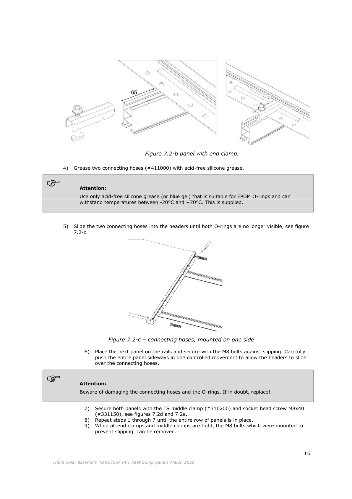
Figure 7.2-b panel with end clamp.
4) Grease two connecting hoses (#411000) with acid-free silicone grease.
Attention:
Use only acid-free silicone grease (or blue gel) that is suitable for EPDM O-rings and can
withstand temperatures between -20°C and +70°C. This is supplied.
5) Slide the two connecting hoses into the headers until both O-rings are no longer visible, see figure
7.2-c.
Figure 7.2-c –connecting hoses, mounted on one side
6) Place the next panel on the rails and secure with the M8 bolts against slipping. Carefully
push the entire panel sideways in one controlled movement to allow the headers to slide
over the connecting hoses.
Attention:
Beware of damaging the connecting hoses and the O-rings. If in doubt, replace!
7) Secure both panels with the TS middle clamp (#310200) and socket head screw M8x40
(#331150), see figures 7.2d and 7.2e.
8) Repeat steps 1 through 7 until the entire row of panels is in place.
9) When all end clamps and middle clamps are tight, the M8 bolts which were mounted to
prevent slipping, can be removed.

16
Triple Solar assembly instruction PVT heat pump panels March 2020
Figure 7.2-e middle clamp prepared
Let op:
The cut-outs on both sides of the middle clamp must fall over the upright ridges of the panels!
This is to ensure the locking of the connecting hoses, see figure 7.3d + 7.3e.
Figure 7.2-f cross-section of attached connecting hose and middle clamp.
Mounting the TS clamping profile
Now that the whole row of panels is in place and it has been checked that the alignment of the panels is
correct, it is time to connect TS clamping profiles to the panels.
1) Slide the TS clamping profile (#311000) sideways (in the longitudinal direction of the mounting
rails) over the middle support of the panel until it clicks into the panel profile, see figure 7.4-a.
2) Secure the TS clamping profile by bending the ridge upwards, indicated by a C. in figure 7.4-b.
Figure 7.2-d middle clamp fixed

17
Triple Solar assembly instruction PVT heat pump panels March 2020
Attention:
The TS clamping profile must be clamped accurately both horizontally and vertically. The TS
clamping profile cannot shift sideways after this.
Mounting connecting hoses and/or connection plugs
1) Grease connecting hoses and/or connecting plugs (use silicone grease only, see also the
instructions for the connecting hoses in chapter 7.2).
2) Slide connecting hoses and plugs into the header at the intended location.
3) Place retaining clips over the header and the slot in the connecting hose/plug. See figure 7.4-a,
location indicated with a D.
Connecting the PV panels electrically
•The instruction for the electrical connection of the heat pump panels is identical to regular PV
panels.
•The electrical connection may only be carried out by qualified electricians. We therefore
recommend that you accept invitations from your inverter supplier to attend the free certification
courses.
•Depending on the situation and requirements of the customer, the choice can be made to use
optimizers or string inverters.
Mount optimizers, if you use them, as far as possible at the bottom edge of your panel field so that you can
always access them easily for maintenance. If necessary, use extension cables to connect the panels to the
optimizers in higher rows. (see figure 7.5-a)
C.
D
Figure 7.3-a bend the ridge upwards
Figure 7.4-a Attach retaining clip at (D)
18
Triple Solar assembly instruction PVT heat pump panels March 2020
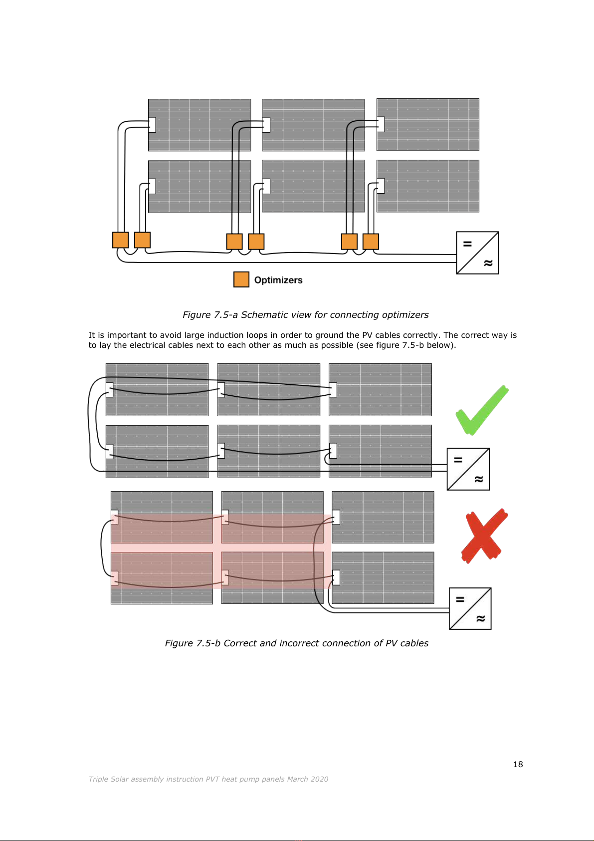
Figure 7.5-a Schematic view for connecting optimizers
It is important to avoid large induction loops in order to ground the PV cables correctly. The correct way is
to lay the electrical cables next to each other as much as possible (see figure 7.5-b below).
Figure 7.5-b Correct and incorrect connection of PV cables

19
Triple Solar assembly instruction PVT heat pump panels March 2020
8. Connecting the pipes
Material and position
•When connecting the heat pump to the heating circuit, always use a bronze connector between
the copper pipes of the heat pump and the c steel of the heating circuit.
•The piping between the heat pump panel and the heat pump can be realized in different ways:
Stainless steel pipe, copper pipe, plastic multilayer pipe (PEX) or plastic PP-R pipe. (do not use C
steel)
•Plastic pipes lying in the sun should always be protected against UV light by means of a UV-
resistant sheath or UV-resistant paint. The plastic pipes must be suitable for the source fluid.
•Make sure that the flow in the source circuit is limited as little as possible, e.g. by using knees
and/or pipes with an inner diameter that is too small.
•Do not install any piping under the panels. It blocks the air flow underneath the panels and makes
maintenance difficult.
When connecting several heat pump panels, consideration should be given to limiting pressure loss. The
advice is a connection according to Tichelman.
•For a pitched roof installation see figure 8.1-a.
•Tichelman is not always necessary for smaller fields.
•With a flat roof installation in rows of 2 panels, the return pipe is always at the highest point of
the panels.
Connecting Tichelman is mandatory:
•≥5 rows of panels
•≥5 panels per row
When propylene glycol is used, Tichelman is required:
•≥4 rows of panels
•≥4 panels per row
Figure 8.1-a Double-sided Tichelman connection
This manual suits for next models
1
Table of contents
Other triple solar Solar Panel manuals

Popular Solar Panel manuals by other brands


Viessmann
Viessmann VITOVOLT 200 5458 installation instructions

Ferroli
Ferroli SIS. ECOTECH 2 F 160 installation instructions

Projecta
Projecta SPA100 operating instructions

Freeloader
Freeloader SC8100 user manual

Viessmann
Viessmann Vitosol 100-FM SV1F Installation, operating and service instructions

ESDEC
ESDEC FlatFix Fusion manual


