Triumph TR6 1976 User manual

RIU

TRIUMPH TR6
HANDBOOK
i
'
ROVER
TRIUMPH
SALES
or
ROVER TRIUMPH SERVICE
Coventry CV4 9DB
England
I
JAGUAR and ROVER TRIUMPH Parts and Accessories
P.O. Box 150, Coventry CV4 9DB
England
BRITISH LEYLAND MOTORS INC.
i
600 Willow Tree Road
Leo~ia,N.J. 07605
BRITISH LEYLAND MOTORS CANADA LTD.
l
P.O. Box 5033, 4445 Fairview Street
Burlington
Ontario L7R 4A3
Canada Publication Part No. 545111176

TRIUMPH TR6

Introduction
Dmmm
AND
BUILT
to give long and co~lsistenttrouble-jke service,
your TR6 embodies inany new safety features, the very presence of which will
add to your conjidence.
Read carefully the contents of tlk book ivl~ichgives, ill the simplest
possible terms, information vital !o theproper operation, care and regular
maintenance of the car.
The TR6 complies with, and in many cases exceeds, all current Federal
and State Regulations concerning Safety, Engine Crankcase Emission and
Fuel Evaporative Control.
Because
of
these regulations, owners ure strongly urged to read the Emission
Control System, Maintenance and Wurlmlty i~lformationin this handbook.
The operations carried out by your Dealer will be in accordance
with the current recommendations and may be subject to
r'ei'isionfrom time to time.
Thesepublications should be passed to each subsequent owner of
the vehicle and the Servicing Details completed to ensure that the
vehicle is kept within the Federal limits in respect of the
Clean Air Act.

LOCATION OF VEHICLE IDENTIFICATION (V.I.N.)
I
NUMBER
Note.
L.H.
and
R.H.
refer to Left-hand and Right-hand
Important
I
side of the vehicle viewed from the driving position.
I
-
quote the V.I.N. Number Engine Number-On
L.H.
side of Cylinder Block
Paint and Trim Numbers Gearbox Number-On L.H. side of Housing
In all communications relating
to Service or Parts please
I
Rear Axle Number-On Hypoid Housing Flange
V.I.N., Paint and Trim Numbers-On rear door pillar
(may be seen by opening driver's door). Also on
a
tag
visible through the windscreen on the left hand windscreen
~illar.
Theinformationcontained herein applies toa range of vehicles and not to a specific vehicle. For the specification of a particular vehicle, an Owner
should consult his Dealer.
The manufacturersreserve the right tovary their specifications with or without notice, and at such times andin such manner as they think fit. Major
as wellas minorchanges may be involved inaccordancewith the Manufacturer's policy ofconstant product improvement.
Whilst every efforlis oadetoensurethe accuracy of the particulars contained
in
this Handbook neither the Manufacturer nor the Dealer, by whom
this handbook is supplied, shall inany circumstancesbe held ],able for any inaccuracy or the co&equences thereof.
All rightsreserved. Nopart of this publication may be reproduced, stored in a retrieval system or transmitted. in any form electronic mechanical
photocopying, recording or other means without prior written permission from the Service Division
of
Rover Triumph 'Motors ~riishLeyland
(U.K.) Ltd Coventry,England.
UNIPART
Parts Service
Replacement parts are not supplied from the factory direct to the general ~ublic,but are directed through Distributors who, in turn, supply their
Dealers.
Genuinespareparts are marketed under the trade mark "Unipart" and carry the same guarantee period as the original part. The same high quality
material is used and the strictest accuracy maintained during manufacture. You are advised, therefore, to ins~ston the use of these parts should
replacements be necessary. Remember, parts which do not carry the trade mark "Unipart" will invalidate the guarantee if fitted to your vehicle.
The descriptions and illustrations appearing in this book are not binding. The MANUFACTURER therefore, reserves the right
-
whilst
retaining the basic features of the Models herein described and illustrated
-
to make at any time, hhout necessarily brin@ng this book
up-to-date, any alteration to units. parts or accessories deemed convenient for improvement or for any manufacturing or commercial reason.

List
Sections
Page
Introduction .
.
.
. ..
.
.
.
.
..
..
3
Location of unit numbers
.
.
.
.
.
. ..
..
4
Controls. Instruments and Indicators .
.
.
.
..
6
Safety Harness
.
. .
.
.
. .
.
.
. .
.
14
Seats
..
.
. .. .
. .
.
.
.
.
.
.
.
15
Locks and Keys
..
.
.
.. ..
.
.
.. 16
Soft Top .. .
.
.
. ..
.
.
..
.
. 18
Hwd
Top .
.
.
.
.
.
.
. .
. .. .
.
20
Care of Bodywork .. .
.
..
.
.
.
.
.
.
21
Wheel
and Tires ..
.
. ..
.
.
..
.
.
22
Cooling System
..
.. .
.
.
. .
.
.. 25
Electrical System
..
.. .
.
.
. .. .. 28
Driving Recommendations ..
.
.
.
.
. . .
.
37
Routine Servicing
.
. .
.
.
. ..
.
.
.
.
39
Emission and Control Evaporative System .
. ..
.
.
40
Periodic Checks ..
.
. .. .
.
..
.
.
49
Regular Maintenance .
.
.
.
.. .
. ..
51
Lubrication Specification ..
.
.
.
. ..
.
. 66
Windshield Wipers .
.
.
.
.. .
.
.
. .. 67
GeneralSpecification.
.
.. .
.
.
.
.
.
.
.
68

CONTROLS, INSTRUMENTS AND INDICATORS
3
32
Fig.
2

CONTROLS, INSTRUMENTS AND INDICATORS
KEY
TO
FIG.
2
Fresh-air vents
15.
Instrument illumination rheostat
Turn-signal control
16.
Fuel gauge
Windshield wiper washer switch 17. Seat belt warning indicator
Lighting switch
Overdrive switch (optional)
Speedometer
Hazard warning switch and indicator
Horn-push
Tachometer
Headlight dipper switch
Ashtray
Oil pressure gauge
Temperature gauge
Brake-line failure/handbrake warn-
ing indicator
Voltmeter
Glove-box lock
Fresh-air vents
Air conditioning (optional) outlets
Choke control
Heat control
Blower switch
Air distribution control
Gear shift lever
Hand-brake lever
Interior light switch
Air conditioning (optional) control
panel
Ignitionlsteering column lock
Throttle pedal
Brake pedal
Clutch pedal
Trip reset control
Hood release control
E.G.R. service indicator
High-beam indicator
Turn-signal indicator
Oil pressure warning light
to
Ignition warning light
Fig.
5
Odometer
Trip odometer

CONTROLS, INSTRUMENTS AND INDICATORS
The controls, instruments and indicators shown on Figs. 2 and 6 and described in the following pages are positioned within easy
reach of the driver to afford maximum ease of operation and minimum distraction. The bracketed figures in the text cross-refer with
the key on page
7.
Fresh-Air Vents (1)
The swivelling vents can be adjusted to admit cold air only
in
any chosen direction within the limits of movement. Each vent
incorporates a valve, operated by a knob in the center of the
vent. To diminish or shut off the supply of air, turn the knob
clockwise. The air flow may be boosted by use of the blower
motor (See item 24).
Turn
Signal Control
(2)
Move the control lever upwards to operate the right-hand
turn-signal lights or downwards to operate the left-hand turn-
signal lights.
See
(38)
Page 1
3.
Windshield Wiper/Washer Switch
Depress the switchtospray clean fluid onto the windshieldand
release the switch when sufficient fluid has been dispensed.
Turn the switch clockwise to operate the wipers at slow speed
and turn the switchclockwiseagain to operate the wipers at high
speed. Turn the switch fully anticlockwise to switch the wipers
off, when they will automatically return to the parked position
at the base of the windshield.
The wipers and washer will only operate when the ignition
switch is turned 'ON'.
Lighting Switch (4)
Depress the lower portion of the switch to the first position
to illuminate the tail, license plate, parking lights and side
marker lights.
Depress the switch again to the second position to illuminate
the headlights. (See "Headlight Dipper", 10).
Overdrive Switch
(5)
(Optional)
When an overdrive unit is fitted to the vehicle the operating
switch is mounted on the left-hand side of the steering column.
Move the lever up to engage the overdrive and down to release
it. Before using the control, refer to page
38.
Speedometer(6)
Additional to indicating the road speed of the vehicle in
miles
and kilometres per hour, the instrument also combines the
turn signal and high beam warning lights and the total and trip
odometers.

CONTROLS, INSTRUMENTS AND INDICATORS
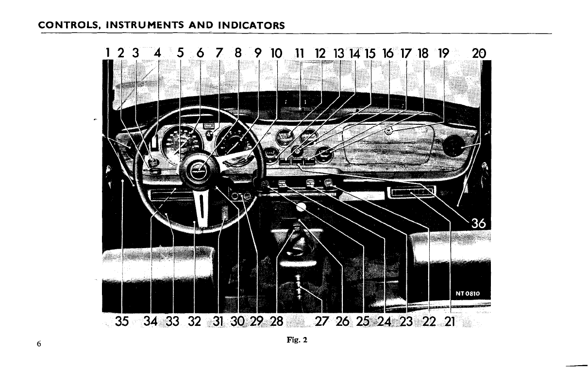
Hazard Warning Switch and Indicator (7)
i
If thevehicle is immobilised and constitutes a hazard to other
vehicles, warning may be given by using the "hazard warning
system". To operate, pull the switch (7) when all turn-signal
lights will flash intermittently.
When the hazard switch is operated, a bulb in the switch will
flash in unison with the exterior warning lamps.
Horn Push (8)
Press to operate the horns.
Tachometer
(9)
The tachometer indicates the engine speed in revolutions per
minute andcombines two warning indicators(39,40. See Fig. 5).
The speed range within the colored segments is subject to the
"Recommended Speed Limits" mentioned on page 38.
Headlight Dipper Switch (10)
When the headlights are illuminated (see 'Lighting Switch' on
page
S),
thehighbeams may be loweredby moving thelever down.
Toreturn to the high beam position, move the lever up.
The high beam position is indicated by a blue warning light
(37) near the bottom of the speedometer dial.
Lifting the lever towards the steering wheel flashes the head-
light high beams.
Ashtray
(1
1)
An ashtray is provided
in
the center of the facia top. To
empty, lift the assembly from the surround.
Oil Pressure Gauge (12)
Oil pressure at 2,000 r.p.m. under normal operating condi-
tions, should
be
45-65 Ibs./sq. in. Severe operating conditions,
such
as
competition work, may cause the oil pressure to drop
below 25 lb./sq. in., indicating that the oil temperature is
excessive. Under these circumstances fitment of anoil cooler may
be
necessary.
Temperature Gauge
(1
3)
When the ignition switch is turned 'ON' the pointer moves
slowly across the dial taking up to one minute to reach a true
reading.
Normal operating temperature is reached when the pointer
registers in the central sector of the dial. Shouldthepointer reach
the highest mark, stop the engine immediately and check the
level of coolant
in
the radiator. Refer to page
49.
Brake-line Failure/Handbrake Warning Indicator (14)
When the ignition switch is turned on the "brake line failure"
and "low oil pressure" indicator lights glow faintly and are
extinguished when the engine is running. Should failure of the
front or rear brake lines occur, the indicator (14) will glow
brightly.
A
broken bulb filament is indicated by the warning light
failing to glow when the ignition is turned on, before starting the
engine.
The warning light will also glow brightly, as a reminder to
the driver, when the handbrake is applied, provided that the
ignition switch is "ON".
9

CONTROLS, INSTRUMENTS AND INDICATORS
Instrument Illumination Rheostat
(15)
Turn the knob clockwise to illuminate the instruments.
Further rotation of the knob diminishes the light intensity-
operates only when the lighting switch is
'ON'.
Fuel Gauge
(1
6)
The fuel gauge indicates the approximate contents of the
fuel tdnk. When the ignition switch is turned
'ON'
the pointer
moves slowly across the dial taking up to one minute to reach a
steady reading which it will maintain regardless of vehicle move-
ment, until the ignition is switched
'OFF'.
Seat Belt Warning Indicator
(17)
A lamp and an audible warning system are actuated if an
attempt is made to start the car without the seat belts in use.
For full details of the system and correct starting sequence see
page 37-'Driving the Car'.
Voltmeter
(18)
This gauge is a battery condition indicator and registers the
battery's state of charge. With the engine running above idling
speed the indicator should register approximately 14 volts. A
reading above 15volts, which continues after
10
minutes running,
is too high and should be investigated. A reading of 13 to 13-5
volts is too low unless the headlamps and other electrical equip-
ment are in use.
Glove Box Lock
(1
9)
The glove box may be unlocked by turning the key a quarter
turn clockwise and opened by depressing the locking barrel.
Fresh Air Vents
(20)
See (1) page 8.
Air Conditioning Outlet
(21)
This is an optional item and reference should be made to
the manufacturer's literature when it is fitted.
Useofthe Choke Control
Under cold ambient temperatures
Pullthe choke control out fully tostart the engine. As soonas
the engine starts push the choke control in until the engine main-
tains an idling speed of approximately 1100 r.p.m. The choke
control should
be
pushed in fully as soon as the engine will
maintain normal running without its use.
Under warm ambient temperatures
Use full choke to fireengine, return to fast idle position when
engine fires, where definite notch will be felt on the cable pull.
After approximately one minute of engine running return the
control knob to the fully in position.
Heat Control
(23)
The heat control operates a water valve which regulates the
flow of water through the heater unit. The control may
be
set at
any intermediate position as required. The water valve is closed
when the control is pushed in; maximum heat is available when
the control is pulled out.
Blower Switch
(24)
The blower motor boosts the flow of air through the heater
unit. Pull the switch to its first position to operate the blower
motor at slow speed or to its second position for high speed
operation. Theblower will operate only when the ignition switch
is turned
'ON'.

CONTROLS, INSTRUMENTS AND INDICATORS
Air
Distribution
Control (25)
i
The air distribution control operates a 'flap' valve which
directs air from the heater unit to the windshield or to the
windshield and interior. The maximum volume of air is
directed to the windshield (for demisting and de-frosting)
when the control is pulled halfway out. When the control is
pulled fully out, air is distributed to the interior and tothe wind-
shield.The'flap' valveisclosedwhenthecontrol ispushed fullyin.
Gear
Shift
Lever
(26)
Moving the gear shift lever from neutral, the gear positions
areas follows
:
1st
.
. .
.
Move the lever left and forward
2nd
.
.
.
.
Move the lever left and rearward
3rd
..
..
Move the lever right and forward
4th (top)
.
.
Move the lever right and rearward
Reverse
.
.
Move the lever sharply to the extreme
right and rearward. Engage only when
the vehicle is stationary.
Always select neutral before starting the engine.
Hand Brake Lever
(27)
To apply the rear wheel brakes pull the hand brake lever
upwards. To release the brakes, pull the lever slightly upwards,
depress the button (arrowed, Fig. 3) and lower the lever while the
button is depressed.
Thebrake-line failurelhandbrake warning indicator will glow
brightly when the handbrake is applied, provided that the
ignition switch is
"ON".
Interior Light Switch (28)
The interior lamp is illuminated when the switch is pulled
outwards.
The lamp is also automatically illuminated when either door
is opened.
Air Conditioning Control Panel (29)
This is an optional item and reference should be made to
the manufacturer's literature when it is fitted.
Fig.
3
11

CONTROLS, INSTRUMENTS AND INDICATORS
Ignition, Starter and Steering Lock Switch (30)
Thecombined
ignitionlstarterlsteering
lock switch is operated
by a special key.
Incorporated in the switch is a "Key Warning System". The
alarm system is fitted to encourage the driver to remove the
ignition key from the lock before leaving the vehicle.
-Separatekeys are supplied for locking the driver's door. The
switch has four positions (Fig.
4)
as
follows:
0
"OFF"
in which position the key may be inserted or with-
drawn (see Key Warning System, page 36).
I "Auxiliary", in this position the ignition circuit is isolated
toallow the use of a radio when thevehicleis stationary and
the ignition is switched off.
I1
"Ignition".
I11 "Start" (Refer to "Starting the engine" on page 37).
Turn the key clockwise to I1 (Ignition) the ignition will be
switched on.
To start the
engine,
the key should be turned a little more
against spring pressure to
I11
("start"), as soon as the engine
fires release the key which will return automatically under spring
pressure to the ignition position (II).
1.
To stop engine and engage steering lock
Turnthekey in ananti-clockwisedirectionfromthe "ignition"
position
(II)
to the "lock" position (0). This action stops the
engine.
Removal of the key in this position automatically actuates the
steering lock mechanism. (See Key Warning System. page 36).
If difficulty is experienced in removing the key, this can
be
rectified by simultaneous movement of the steering wheel.
The Key Warning System only functions when the ignition
key is positioned in the switch and the driver's door is open.
The "warning" denoted by a continuous buzzing sound will
terminate when the driver's door is closed or the ignition key is
completely removed.
(See
page 36).
2.
To disengageSteering Lock and Start Engine
Insert the key and turn in clockwise direction. If difficulty
is
experienced in turning the key, this can be rectified by simul-
taneous movement of the steering wheel.
I
I
Fig.
4

CONTROLS, INSTRUMENTS AND INDICATORS
'Ihroffle, Brake
and
Clutch Pedals
(31, 32
and
33)
t
These are conventionalitems which should require no further
explanation.
TripReset Control
(34)
The trip odometer
(42)
may
be
reset to zero by pushing the
knob
(34)
upwards and turning anticlockwise.
HoodReleaseControl
(35)
To open the hood, pull the control knob located below
the parcel shelf at the left hand side of the car. This disengages
the locking plate and allows the hood to rise sufficiently for
the safety catch to be released using the fingers. See page
17.
Fig.
5
E.C.R. WarningLight
(36)
Refer to page
43
Emission and Evaporative Control System.
High BeamIndicator.
(37,
Fig,
5)
The indicator glows blue when the headlight high beams
are selected and is extinguished when the headlights are 'dipped'.
Turn Signal Indicator
(38,
Fig.
5)
Indicates the
correct
functioningof the turn signal lights when
operated by thelever
(2).
A
broken lilament in a bulb on oneside
of the vehicle is denoted by the non-operation of the indicator
light when the lever is
in
the relevant operating position.
A
defective flasher unit or broken filament in the indicator bulb
will
be
indicated by no light response from the lever in both
directional positions.
OilPressure Warning Light
(39,
Fig.
5)
Thecenter indicator glows orange when the ignition is switched
on and is extinguished when the engine runs in excess of idling
speed. Should the light remain on at normal running speeds, stop
the engine and check the level of oil in the engine oil pan. If this
is satisfactory, have the lubrication system checked immediately.
IgnitionWarningLight
(40,
Fig.
5)
The indicator glows red when the ignition is switched on and
is extinguished when the engine is running. Should the red light
remain on whilst driving,
a
fault
is
indicated in the battery
charging systemwhich should
be
rectifiedwithout delay.

CONTROLS, INSTRUMENTS AND INDICATORS
Odometer (41, Fig.
5)
The figures within the aperture below the center of the speed-
ometer dial show the total mileage of the vehicle and may be
used as a guide for periodic lubrication and maintenance.
Trip Odometer (42, Fig. 5)
The figures within the aperture above the center of the
speedometer dial may
be
used to record the distance of each
journey, provided that the figures are initially set at zero. (See
'Trip Zero Control', 34.)
RadioControls
Theradio aeriel fitted tothe left front wing is raised by pulling
the protruding tip upwards. The aeriel should always be lowered
before the car is put through an automatic car wash plant.
Two radio speakers are fitted in the facia consol for connec-
tion to an approved radio receiver. Refer to the radio leaflet
supplied with the set for operating instructions.
Sun Visors
Two adjustable sun visors, padded to reduce the risk of
impact injury, may be unclipped fromthe centre support brackets
and swung to eliminate side glare. The passenger's sun visor
incorporates a vanity mirror.
Rear View Mirror (See page 20)
SAFETY
HARNESS
Safety harness anchorage points are built into the vehicle and
automatic, reel type safety belts are fitted before the car is
delivered.
Using the Harness
Ensure that the buckle unit is conveniently situated by the
side of the seat and pass the seat buckle over the shoulder nearest
to the car door. With the lap and body belts passing across the
body, plug the belt buckle into the nearest centre buckle unit.
This is denoted by a positive 'click'.
Torelease the harness depress the marked panel onthecentre
buckle unit.
SeatBelt WarningSystem
Theseat belt warning devicewill operateif an attempt is made
to start the car without the seat belts in use. For full details see
page 37 "Driving the Car".
Cleaning
Badly stained safety belts can be dry cleaned. The cleaner
should be advised of the nature of staining. Belts subjected to
normal soiling can be cleaned with soap, or detergents dissolved
in hot water.
Inertia Reel Mechanism Check
Every 10,000 km (6000 miles), carry out the following road
check to ensure that the safety harness inertia reel mechanisms
for both driver and passenger continue to operate satisfactorily.
IMPORTANT. Road tests must only be carried out under
maximum safe road conditions, i.e. level, dry road with no
following or oncoming traffic of any kind.
(a) With the safety harness fitted to driver and passenger as
previously described, start the engine and accelerate the
vehicle to approximately 24 km/h (15 m.p.h.). Ensuring
that it is safe to do so, brake sharply.

S
EATS
(b) The safety harness should automatically lock, holding both
driver and passenger securely in position.
It is important when braking that the reaction of both driver
and passenger is normal, i.e. the body must not be thrown
forward in anticipation, thus causing a 'snatching' action
of the reel which will not operate the locking mechanism.
The harness is locked by retardation of the car, not by body
movement.
SEATS
The seats areof the bucket type and haveadjustable headrests
to prevent the effects of backlash in an accident. The seats are
pivoted at the front and secured at the rear by a spring loaded
lever
A
(Fig. 2) which prevents the seat liftingduring anaccident.
The lever, when moved forwards allows the seat to be tilted and
access to
be
gained to the rear of the driving compartment.
To clean the seats refer to page 21 "Care of Bodywork".
Adjustments
The seats areadjustable for leg reach (fore and aft movement)
and squab angle (back of the seat rake).
Leg reach adjustmerzt
This is adjusted by moving the lever (Fig.
1)
situated at the
front of the seat and sliding the seat to the position required.
Release the lever and try to slide the seat to ensure that the lever
is correctly located and the seat is secure.
Squab angle adjustment
Sit in the seat, lift the lever B (Fig. 2) and assume the desired
posture, release the lever.
Fig.
2
(lower)
15

LOCKS
AND
KEYS
LOCKS
AND
KEYS
Keys
The followingkeys are supplied with each new TR6.
2
Ignition keys.
2
Door keys.
2
Glove locker and trunk locker keys.
In addition, an ignition key identification discis supplied and
must be submitted to your Triumph dealer when new
ignition keys are required.
As
the disc is the only record of the
ignition keys it should
be
kept in a safe place.
Door Locks
"Anti-burst" locks are fittedto both doors and are opened by
a push button on the outside or by a remote control lever on
the inside.
To lock the door, insert the key and turn forward a quarter
turn. Tounlock a door turn the key rearward a quarter turn.
Ignition/Steering Lock
and
Key Warning System
See
page
12
for operation.
Lubrication of Exterior Locks
Once a month, particularly in sub-zero temperatures, apply
a few drops of light machine oil to the latch and key slots. Do
not apply grease to lock cylinders.
16
Fig. 1
(left)
Fig.
2
(upper) Fig.
3
(right)

LOCKS
AND
KEYS
Fig. 4
(left)
Fig.
5
(upper) Fig.
6
(right)
Hood Release (Fig.
1)
To open the hood pull the control situated below the left-
hand side of the facia. The hood will rise sufficiently to enable
the fingers to be inserted under the
R.H.
rear edge to give acces
to a near vertical position, where it will be supported by a stay.
Disengage the stay from its recess before attempting to close the
hood.
Trunk Locker (Figs.
4
and
5)
To open the deck lid, depress the unlocked plunger (Fig.
5)
and raise the lid to its limit before loweringit on to the telescopic
support.
Close the lid by raisingit slightlyto releasethe catch(arrowed,
Fig.
4)
in the telescopic support and lower the lid, which
may be locked by turning the key a half turn counter-clockwise.
Fuel Filler
Cap
(Fig.
6)
The fuel filler cap, Iocated forward of the trunk lid, is opened
by lifting the catch at the side of
the
cap. Press the cap to close.

SOFT
TOP
The soft top is made from P.V.C. material, and is supported
by a hinged frame. The assembly folds down into the rear of the
car and is protected by a soft top cover.
Lowering the Soft Top
Release the soft top header rail from the windshield frame by
turning the catch levers in the direction as shown in Fig.
1.
Release the fasteners (five) securing the hood material to the
rear crossframe.
TOP
Release the fasteners (six) below each of the rear quarter
windows (Fig.
5).
Push the header rail, rearwards and slightly upwards, while
knocking the soft side support (arrowed Fig.
2)
downwards
until the assembly begins to fold. Continue lowering the frame
and pull the fabric flat over the deck lid (Fig.
3).
Fold the fabric forwards over the soft topframe and turn the
ends of the fabric inwards (Fig.
4).
Ensure, that the Vybak
windows are free from distortion and that the fabric is clear of
the frame.
Fig. 1
18
Fig.
2
Fig.
3

SOFT
TOP
Soft Top
in
the
Down Position
Retain the soft top in position by fitting the cover as follows:
Attach the cover to the outer fasteners and continue working
towards the center. Attach each strap to its respective fastener
on the back wall of the floor well.
Raising the Soft Top
Unfasten and remove the soft top cover. Fold the sides of the
fabric outwards and pull rearwards over the deck lid. Lifting the
front header rail, raise the assembly sufficiently to allow the
fabric to lie evenly over the soft top frame.
Secure the soft top header rail on the windshield frame, by
turning the catch levers inwards towards the center of the car.
Secure the soft top to the body using the fasteners below
each quarter window (Fig.
5).
Secure the fasteners securing the inside hood material to
the rear cross frame.
Opening backlight
(Fig.
6)
To open the backlight, release the zip fastener and roll the
panel downwards. Retain the rolled panel in position by
attaching the straps to the press fasteners located on the back
wall of the rear compartment.
Fig.
4
Fig.
5
Fig.
6
19
Table of contents
Other Triumph Automobile manuals

Triumph
Triumph TR8 1980 User manual

Triumph
Triumph TR2 Operating instructions

Triumph
Triumph TR3 User manual

Triumph
Triumph Spitfire MK3 User manual

Triumph
Triumph TR6 1969 Manual

Triumph
Triumph TR7 User manual

Triumph
Triumph 1961 TR4 User manual

Triumph
Triumph TR7 User manual

Triumph
Triumph TR6 Trophy User manual

Triumph
Triumph MAYFLOWER 1951 User manual

Triumph
Triumph TR6 PI User manual

Triumph
Triumph TR4 User guide

Triumph
Triumph TR4A User guide

Triumph
Triumph TR4 User manual

Triumph
Triumph TR6 Trophy Operating instructions

Triumph
Triumph TR2 User manual

Triumph
Triumph Dolomite Sprint User manual

Triumph
Triumph 1800 1951 User manual

Triumph
Triumph TR4 Instruction manual

Triumph
Triumph TR8 User manual