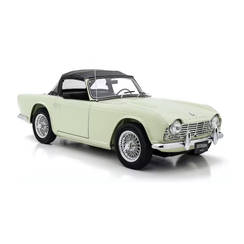
Triumph TR4A User guide

HANDBOOK TR4A

IMPORTANT
IN THE INTERESTS OF SAFETY, THE IMPOR.
TANCE OF MAINTAINING CORRECT TYRE
PRESSURES
CANNOTBE
OVER
EMPHASTSED.
PRESSURES
SHOULD BE
CHECKED
AT LEAST
EVERY
TWO WEEKS
OR
1,000
MTLES
(1600
KMS.)
AND MAINTAINED IN ACCORDANCE
WITH
RECOMMENDATIONS GIVEN ON PAGE 58.

TRIUMPH TR4A
OWNERS HANDBOOK
Issuedb!
STAN DARD.TRI UMPH SALES LTD,
COVENTRY, ENGLAND
A memberof theLeylad Motors Corporation

FOREWORD
Surress, rlre osDirution of all human pursuits. has. in theworlil of motor sport. bccomesynonymous with the
nane of Triuiph. The-many
loureli obtained
by T,R.'s in intprnational
and locolcompetitions
haD?
gained
them ait enviabie rcputotion i7 *hi"h ,urry ownir is justifably ptouil.
The newestof the Ttiumph thotoughbreds,
the T.R.AA, combines
na@deuelopments
with thewellprou.enrally
rcsred
featuris ol its predicessors. -Wcwelcom"owaersto on eDprb;ilening circle of enthusiasts
and uish them
many-pledsont'houri of motoring in aililing nao honours to a name alreaily renowr.eil.
To cnsurea continuance
of thcsuperbperiormonce whieha
-T.R,4A.is capable
ofgiuing. coupledwith reliability
anil economy,regular core onil dttention ore neccssary. Au essennalinJormalton anclthPpcrtods allpr unr.n
attention is"recokmended., are cotutained, in the following pages, Owners ate aih;ised to read them carefully
and noteparticularly the ad'aiceon lubrication'
New.parts or accessories,
when needed,,
arc obtainable only through authofiseil Triumph dealers, u;ho in
ad,ilition to being trained n girn expert adnice and attentiin, are also equipped to utuilertaherepairs and
ooerhauls which are bevonil the scopeof most owners,
STANPART
Spare Parts Service
Rept@ment pdrs are nol supplied from ltre facrory.Iirect ro the gen€ral public, but are diEted throush Distributors who, id turn, supplv their
cenuire spe parls are markered under rhe uade marl Sldpan an<tcaiiy rhe samegu&mlee as lhe orieinal parr. The"samehigh qualirv
dalerial is:u$d dd rhe srricLed
aeuracy mainrsined duritrg muufacture, you are advi$d. (heeibre. ro iosist on the useol Lbese
pans shouro
iliii!1.;,!i,ti.;; ii-""1,"".v.^'i;];;-b.;;i.i;iii"t d. noirc'arrv rhe trade nrk stanpa( qil invaridare rhe eueant@ if nlted 10 vou. vehicre.
The .lescriorions and iltu{rarions aDDearinsin rhis boor are nor bindine. The MANUFACIURER, therefore. rcFru€s $e rishl-$hilst
*li','iiii if,l "r;liil-i."'ii'Li ,liiii'iriiiir":t'ii.i,' desribed atrd irrusrar;d - ro make at atry ride. ivithour Decas&lv brinsitre.rhis book
;;:6:a'"i.'5ffi;";ii;;;i i; ;"f;;';G;ori!s aeenea oaveueot ror imp.oveFeat or fo' itrv meufactu'ing or comerciar r€ason'
CONTENTS
Pate
4
7
l0
ll
l3
l5
29
3l
33
InstrumentsandIndicatols
Switches
andControls ..
HeatingandVentilation
LocksandKeys ..
Ddving Reconmendations
Routine
SeNicing
Cooling
System .. ..
RoadWheelsandTyres ..
Running
Adjustments ..
ElectricalSystem.. ,.
softTop ..
SurreyTop
Careof Bodywork
Recommended
Lubricants
GeneralSpecification ..
RoadSpeedData.. ..
Tyre Pressures
Index
Pate
40
46
48
5l
52
54
5'l
58
63
IMPORTANT
In all communicationsrelating to
Service or Sparespleasequote the Commission
Numb€r (ChassisNumber),
andPaint andTrim Numb€rs
I-OCATION OF CO]IIDtrSSION AAID LINIT ]\{IMBERS
Commission,
Paintand
Trim Numbers-On Scuttle
Panel. (May
be seen
by lifting the bonnet.)
Engine
Number-On L.H. side
of Cylinder
Block.
GearboxNumber-On L.H. sideof housing.
Rear AxIe Number-On faceof HyPoid Housing Flange.

INSTRUMENTSAND INDICATORS
Fig. 1 (above) Fig. 2 (below)
l, Fresh
Air VcntControls.
2. Tum SignalControl.
3. Tachometer.
4. Turn Signal
Indicator.
5. Ignition WamingLight.
6, Hon Button.
7. Speedometer.
8. Lightingswitch.
9. WaterTemperature
Gauge.
10.
Oil Pressure
Gauge.
Il. FuelGauge.
12.AshTray.
13,Arruneter.
14.FaciaLocker.
15,FreshAir VentControl.
16.HeadlampDipper Switch.
17.ClutchPedal.
18.BrakePedal.
19.Accelerator
Pedal.
20. PanelRheostat
Switch.
21, WindscreenWasher
Control.
22, Windscreen
WiperSwitch.
23. HeatControl.
24. GearShiftLever.
25. Heater
Blower
Slvitch.
26.HeatDist butionControl.
27. Ignition/Starter
Switch.
28.Handbrake
Lever.
29. ScuttleVentilator
Control.
30.ChokeControl.

INSTRUMENTS
AND INDICATORS
INSTRUMENTS AND I]\DICATORS
The instruments, indicators and controls shown on Figs. I
and 2, and indicated in bracketswithin the text, perform the
following functions:-
Tachometer(3)
The tachometer, indicates the engine speed in revolutions
per minute and is calibrated in divisions of 100,extendingto
6,000. The speedrange within the red segmentis subject to
specialprecautions. Thesearegiyenon page14.
Turn Sienal Indicator (4)
The greenflashing indicator monitor light, glows intermit-
tently when the direction control is operated and the ignition
is switched on. See
"T\rm SignalControl" on page9.
Flesh Air Vents (1 and 15). Refer to page10.
Ignition Wamiry Light (5)
The small red warning light glows when the ignition is
switchedon and is extinguishedwhen the engine is acc€lerated.
Shouldthe indicator continueto glow whentheengineisrunning
aboveidling speed
anelectricalfault is indicated li,hich should be
traced and rectified immediately.
Spe€dometer
(7)
The speedometer
indicates the road speedof the vehicle in
milesperhour andiscalibratedin divisionsof 2,extendingto I20.
The fiqureswithin the aperture above the centre of the dial
may be fsed to recordindividualjoumeys. Provided
that the
figures are re-setto zero at the beginning. This is achievedby
pushing
up and turningclockwise
the knob which extends
downwardsfrom behind the instrument.
The figureswithin the aperture below the c€ntre of the dial
showthe total mileageof the v€hicleard may beusedasa guide
for periodic lubdcation and maintenanca.
The High Beamindicator near the bottom of the dial glows
only whentheheadlampmain beams
arein use. WhenthediPper
switch is operated tbe indicator is extinguished.

INSTRUMENTSAND INDICATORS
Water TemperatureGauge(9)
Normal operatingtemperature
is reachedwhen the needle
registersin the centralsectorof the dial. Shouldthe needle
reachthehighestmark,stoptheengineimmediately,allowit to
coolandcheckthelevelof the
coolant
intheradiator. Whenthe
ignition isswitchedon the needlemovesslowlyacrossits scale,
takingup to one
minute
to reacha truercading.
Oil PressureGauge(10)
The oil pressurereliefvalveis setto controlthepressureat
65-75lb. persq.in. at 2,000r.p.m.withnormal
oil temperatures.
i.e.,about ?O'C. During sustainedhigh speedoperation,
th
resulting increasein oil temperaturemay cause
the oil pressur
to drop. Thiswill haveno detdmentaleffects
providingit do(
not fall below30lb. persq.
in.
Severeoperatingconditions,suchascompetitionwork, ma
causetheoil pressuretofallbelow30p.s.i.,indicatingthatthe
o
temperatureis excessive.Under thesecircumstances,
an o
coolerkit is recommendedto ensurethat a maximum
sumpo
temperatureof 125"C.is not exceeded.
Fuel Gauge
(ll)
The fuel gaugeindicatesthe approximate
contents
of tt
fueltank. Whentheignitionis switchedon, theneedlemov(
slowlyacrossitsscaletakingup to one
minuteto reach
astead
readingwhich it will maintain,regardlessof vehiclemovemen
unril the ignition is switched
otr
Ammeter (13)
The ammeteris calibratedin amperesand indicatesthe ra1
of batterychargeand discharge.The chargingrateis indicat€
whenthe pointer movesto the left-handsideof "zero", an
discharge.
b) movementto theright.

SWITCHES AND CONTROLS
Fig. 4
Panel R.heostat
Switch (20)
Turn the knob clockwise to illuminate the instruments.
Futher rotation of the knob diminishes the light intensitv.
Operate
only when
thelightingswitchis "on".
Lighting Switch (8)
Move thecolumn switchleverdownwardsto thefust Dosition
to illuminate
theside,rear,numberplateandcentreinstrument
panel lights. Move the lever down to the s€condposition to
illuminate the headlamps. See
"Dipper Switch", page8.
Witrdsq€en Washer Control (21)
Use the windscreenwashercootrol in coniunction with the
windscreen
wiper. Operateby pushingtheconirol to sprayclean
fluid on to the screenasthewiper bladesdispers€
themud. If the
washerhasremainedunusedfor some
time, depressthecontrol a
few times to charge the system.
Windsqeen Wiper Switch (22)
Pull the switch knob to its first position to operatethe wipers
at fast speedand to its second
position to operatethem at slow
speed. Pushthe knob fully hometo switch off, whenthe wipers
will automatically return to theparkedposition at the baseof the
windscreen. The wipers canonly beoperatedwhenthe ignition
switch is turned to the "ignition" or auxiliary positions,
Ignition/Starter Switcb (27)
Op€ratedby a separatekey, thecombinedignition and stalter
switch has four positions. Theseare: l, "Off", in which

SWITCHES AND CONTROLS
I. OFF
^ 2. IGMTION
J 3. srART
4. AIIXILIARY Flg.5
positiont}Ie
keymay bewithdrawn; 2."Ignition" ; 3, Start ;
4.Auxiliary. (See
Fig. 5.)
With the key in the "Off" position (vertical),
turn the key
clockwise
to switchontheignitionandauxiliarycircuits.
To operatethe starter motor, turn the key further clockwise
againstspring
pressure
and
when
rheengine
fires.releasethe
key.
*hich *il-tretumto the
"lgnition" Position.
It theenBineias
failedtostart,
waituntil thestarter
motorhascome
to restbefbre
retumiug
thekeyto the"Start" Position.
To select"Auxiliary" turn the key anti-clockwise from the
vertical position. This will enable,for €xamPle,thc radio to be
usedwitj\ the ignitioo switched off and, sincethe key must be
withdrawn fronithe switchto lock the vehicle,accessodes
cannot
continuetofunction.
Choke Control (30)
Thechokecontrol isusedto enrich thefuel mixture for easier
startiog
from cold. Thecontrolshould
not beusedif theengine
3
is warm. and mav not be oe€gssary
in walm climates. Full in
structions for its'use are given urider "starting' on page 13
Headlamp Dippr Switch (16)
A footoperated
dipperswitch,
locatedon thetoe-board
toth
left of the itutctr peAai,
enables
theddver to quickly lowerbi
headlampbeamswhilst maintaining full conhol of th€ stocrin
andotharhand
controls.
When the headlampsare illuminated, seelighting switch o
page
7.themain beams
maybelowered
by pressing
thedippe
iwi-tch
and releasing
ir. To retum lo the main beam
Positior
apainDress
rhe dipier switcband releaseir. The main bear
p6sition
is indjcate'd'
by a redwaming liSht nearthebottom (
ahespeedometer
dial.
Hom Button(6)
Operatethe homs by prcssingthe button in the c€ntreof tt
steeringwheel.
Overd ve Control (SPecial
Accessory)
Whenanoverdriveisfitted, thecontrol ismountedon thesi(
of thesteering
column
cowlthat houses
theturn signal
contrc
Move the lever up to engage
overdrive and down to release
i
Before
using
thecontrol,
see
page
14

SWITCHES
AND CONTROLS
Turn Signal Control (2)
Theturn signal
lampsarecontrolledby a lever
mountedon
theoutboardside
of thesteeringcolumncowl. Beforemaking
a right-hand turn, move the lever clockwise. Move it anti-
cloc[wisebefore
tuming left. When eitherleft- or right-hand
turn signal
lampsareoperating,a greenindicatorlight on the
facia,flashesintermittently,
Clutch,
Brake and AcceleratorPedals
(17,18and 19)
Theseare conventionalitems which do not needfurther
explanation.
Gear Shift Lever (24)
AUforwardgealshavesynchromeshengagement.See
Fig. 6
for the gearshift positions. Reverseis engagedby movingthe
gearshift
leverto theright,liftingit andther movingit rearwards.
HandbrakeLever(28)
To applythe
rear
wheelbrakes,pull thehandbrukeleverand
retainit in position
by pressingthe button on top of thelever.
Releasethehandbrakebypullingit slightlyrearwardsto freethe
pawl, then allow the lever to move forward to the "OFF"
position.
SeatAdiustment
(Fig.7)
Thedriver's
andpassenger'sseatsareadjustable
for legreach
by moving the leverat the front of eachseatand slidingthe
seatto thedesired
position,
allowingtheleverto re-engagein the
nearestadjustmentnotch. Thepassenger's
seatbackresthinges
forward to provideaccessto the rear compartment.
Radio Controls
For operating
instructionsseetherudioleafletprovided
with
theset. This is protectedagainstelectrical
damageby a 5 amp.
fusehousedin themain leadunion. Seepage40-WARNING.

HEATING AND VENTILATION
IIEATING AND
Theheaterisdesignedto heatanddistributeincomingfreshair,
or if dust and exhaustfumesare being admitted, thc intake duct
may beclosedand theheaterused
to recirculateair aheadyin the
vehicle.
Fresh air is admitted to the heater duct tirough the open
scuttle ventilator, This is opened by pulling t}le ventilator
leyerrearwardsand closedby pushing it forwards.
When the scuttle ventilato! is closed,air is drawn in tbrough
the open facia vents and recirculated by the heater unit, The
facia vents are openedby turning the handwheel,at the side of
eachvent, forward.
When the scuttle ventilator is open, cool fresh air is blown
out of the openfacia ventsand may be directedup or down, or
maybecut-off by adjustingthehandwhe€l. Thereisno provision
for heatinethe air blown from the facia vents.
Vf,NTILATION
The degreeof heat given out by the heaterunit is controlle
by the left-hand control on the heater conhol panel. Pull th
control fully out for maximum heat, or push it fully in for colc
Intermediate positions give varying degees of heat,
The blower switch on the ccntre of the panel controls
motor-driyen fan which stimulates the flow of fresh air fror
outsidewhenthe vehicleis stationarv. and booststhe air cftculs
tioo when the vehicleis moving. The blower is operatedb
pulling the control to switch on, and pushing it to switch of
The distribution of warmed air is effectedby the right-han
control. Pulling the contuol fully out directs air to the intedc
of the vehicle. With thecontrol pushedto the half waypositior
air is dire€tedto the screenfor demisting or defrosting. Inter
mediatepositionsdirect ak to the screenand interior in varyin
proportions. With the control pushedfully home the systemj
inoDerative.
Fig. E
10

LOCKSAND KEYS
LOCKS
Locks and Keys
Twosetsof keysareprovided. One
keyisusedfor operating
theignitionswitchanddoorlocks,andtheotherfor lockingthe
facialocker and luggage
compartment. Thespare
setof keys
is housed
inside the rear lamp at the passenger
side. You are
advised
to recordthe key numberfor future reference,so that
in theeventof loss,replacementkeysmaybeobtainedwithout
diffculty.
Facia Locker (Fig. 9)
The faciacubbybox may beunlockedby turning thekey a
quarterturn clockwiseand openedby depressingthe locking
barrelandpullingon thelippedplate.
AND KEYS
LuggageCompartment
(Fig. 1l)
To open the luggage
compartmentlid, turn the unlocked
handlecounter-clockwise
to a verticalpositionandraisethelid
to itslimit beforeengagingthestay
in theslotProvided.
To closethelid, raiseit slighdyto releasethestay
whichcan
thenbe engaged
in its rubberretainer
on the boot lid suPPort
assembly,
Lower the lid and turn the handle,which may be
lockedby turningthekeyahalfturn counter-clockwise.
Fuel Filler Cap (Fig. 10)
The fuet fitler cap, located forward of the luggagelocker lid,
is opened
by depressinga small lever at the sideof the cap.
PressthecaD
to close.
Fic.ll
ll

LOCKS
AND KEYS
Door Ircks
Either door may belocked from insideor outsidc irrespective
of which door waslast used
asan exit, Themechanismauto-
matically prevents the inside handle being set in the locked
positionwhilstthe dooris open. Thiseliminatesthepossibility
of being locked out of the car in the event of the key being
inadvertentlyleft inside.
Interior Locking
To lock the door it mustbeclosedfust. Only thenwill the
mechanismpemit theinsidehandleto bemovedforwards.The
handle
will automatically
retum to thenormalposition
assoon
asit isreleased.
IMPORTANT. Do not attemptto forcethe handleinto the
locked
positionwhilstthedoor is.open.
Exterior Locking
When leavingthe car, movethe door handleforward and
leavethevehiclebytheotherdoor,whichmaythenbelockedby
usingthekeyasfollows:-
Inse thekeyin thelockandturn it approximately
aquarter
tum towards the shut-face. The key will automatically retum
to rhehorizontalpositionfrom wheieit may bewirhdriwn,
when the dools are locked, pressurgon the outside push
buttons, which may be fully depressed,cannot force or damage
the lock,
l2
To UDlock
Re-enterfrom eitherdoor by inserting
the key in the lo(
and tuming it approximatelya quarter tum away from tl
shut-face.The key will againautomatically
returnto thehor
zontalposition
to enableit to beremoved.
Lubrication
It will be beneficial,particularly
duringfreezing
weather,
l
fuifoduce a few droDsof thin machineoil into the latch slot ar
thelock key slots
ai intervats
of not morethan oncea mont
IMPORTANT. Urder no circumstancesshould greaseI
applied
to the lock cylinders
or keys.
Bomet Release
To openthebonnetpull
the contuol situated below
the right-hand side of tlle
facia. The bonnetwill rise
sufficiendy to enable the
fingersto beinsededunder
therearedgeto raiseit to a
near
verticalposition, where
it will be supportedby a
stay. Disengage
the stay
from its recessbefore clos-
ing thebonnet. Fie.12

DRIVING
RECOMMENDATIONS
DRIVING RECOMMENDATIONS
Running-in
Theimportanceof correctrunning-incannotbetoo strongly
emphasized,for duringthef,Ist500milesof motoring,the
work-
ing surfaces
of a new engine
are beddingdown.
Du ng thisperiodthevalve
seatsstabilise,
causingin some
instances,slightdistortion and preventingproper seatingof a
valve. Avoid possible
damageresultingfrom sucha condition,
by havingthe compressionpressurescheckedearly in the life
of theengineafter "running-in" is completed.If the pressures
areunequal,
valve
grinding
isrecommended.
Furtherattentionto thevalvesshouldnotthenberequiredfor
aconsiderable
mileage,
or until the
pressures
haveagainbecome
unequal.
Whilst no specificspeedsare recommendedduring the
running-inperiod,avoid placing
heavyloadsupon the engine,
suchasusingfull throttle at low speedsor whenthe engineis
cold. Running-in
shouldbeprogressiveandno harmwill result
from theenginebeingallowedto "rev." fairly fastprovidedthat
it is thoroughlywarm and not pulling hard. Always selecta
lowergear
if necessaryto relievetheengJneof load.
Full powershouldnot be useduntil at least500mileshave
beencovered
and eventhen, it shouldbe usedonly for short
periodsat a time. Theseperiodscanbeextendedasthe engine
becomes
moreresponsive.After 1,000milesrunning,theengine
canbe consideredasfully run-in.
Starting the Engine from Cold
Check,
andif necessarytop up,theradiatorwaterleveland
theengineoil level. If thecarhasnot beenusedfor severaldays
and fuel hasevaporated
from the carburettors,
refill them by
operalingthe
primingleveronthefuelpump.
Theslightresistance
ciuseswEenthefloaichambers
arefu .
Apply the handbrakeand ensure
that the gearlever is in
"Neutral". Pull thechoke
control out to its stop and tum the
keyto the"ignition" position. Theignition
waminglight should
then
glowandthefuelgauge
shouldregisterthecontentsof the
fueltank.
From the"ignition" position,
tum thekeyclockwiseagainst
spring
pressurero operatetheslartermotor. lmmediatel)lhe
eigini hres.releasethekey.
whichwill rerurnto the
"igniiion'
position. Shouldtheenginefail to startat thefirst attempt,do
notre-operate
thestarterswitchuntil thestartermotorhas
come
to test.
As soon
asit starts,push
thechoketo the"half-in" position
andwarmtheengineatafairlyfastidlingspeed
ofapproximately
1,500r.p.m. This will causethe ignition waming light to be
extinguished,thusindicating
thatthegeneratorischarging.The
oil gaugeshould
indicatethe pressure
of oil circulating. lf the
gauge
remainsatzero,stop
theengineimmediatelyand
establish
thecause.Failureto do somayresultin seriousdamageto the
eDgroe.

DRIVINGRECOMMENDATIONS
Cylinderwearisminimizedifthe engineiswarmed
upquickly
by driving awayas soonas oil is circulatingafter stadingthe
engine.Do not racetheengineto speedup the processbut, if
possible,maintaina speedof approximately25m.p.h.
until the
chokecanbe
pushed
fully in. In warmclimates,useof thechoke
may be unnecessary.Avoid theuseof full throttle during the
warmiog-upperiod. A themostat incorporatedin the cooling
system
enablestheengineto bewarmed
up quicklyfrom cold.
Starting with the Engine Warm or Hot
Whenre-starting
a hot engine,depresstheaccelerator
pedal
toaboutone-thirdofits travel
beforeoperatingthestarterswitch.
Thechokeconrrolshouldnotbeused.
RecornmetrdedSpeedLimits
Avoidover-rewing,
particularlyintheiowergears.Thedriver
isadvisednotto drivethe
carcontinuouslyatenginespeedsabove
5,000r.p.m.in any gear. However,whilstaccelerating
through
the
gears
it ispermissible
to attain5,500r.p.m.for shortperiods,
thesespeedsbeingindicated
by thebeginningandtheendof the
redsegmentonthetachometer.
Whenan overdrive
is fitted,do not changefrom overdrive
tonormal3rdor2nd
gears
at
enginespeedexce€ding4,500r.p.m.,
otherwisedamagemay resultfrom "over-rewing".
OverdriveUnit (whenfitted)
Ao overdriveunitsenes
asaconvenientmethodofproviding,
atwili,a numericallllower
overallgearratioro rediceenginl
speedandwear,andto efectfueleconomy,
t4
The Laycock de Normanville overdriveunit incorporal
an epicyclicgear train which is engaged,
to give overdri
condition,by a coneclutch movingunder theinfluence
of t
hydraulicpressuregenemtedby a small piston pump. Wh
pressureis released,via a control valve,the clutch is return
and held in direct drive by compression
springs, A ur
directionalroller clutch enablesthe changeinto, or out (
overdriveto bemadewhentransmitting
full power,withoutlc
of road speed.
Thehydraulic
controlvalveislinkedto an electro-magne
solenoidwhichis operated,viaarelay,
by a two-positionswit
mounted
on thestee ngcolumn.
Greatestbenefit
will accruefrom judicioususeof the ov(
drive,the governing
factor beingthat the vehiclecontinues
run easilywithout sign of enginelabouring, combinedwj
theninimum amountof throttleopeningnecessaryto mainte
thiscondition.
Suggested
minimumengagementspeedsare:-
Top gear 40m.p.h.
Third gear 30m.p.h.
Do not changefrom overdriveto normal drive at engj
speedsin excessof 4,400r.p.m.
The abovedisengagement
speedcorrespondsapproximatl
to peakrevs.
in norrnalgears. Disengagementof the O/D
a speedhigher than that stated may cause damage fr(
"over-revving".

ROUTINE SERVICING
ROUTINE
This sectiondescribesthe lubrication and servicinq require-
mentswhichareneaessaryto maintaintbevehiclein g6odorder
and ensuretrouble-free motodng. All points desc bed should
receiveattention at the prescdbed intervals,
Engrne
When a new car is delivered,the enginesump containsa
special
running-inoil which shouldbe retaineduntil the com-
pletion of 1,000miles. Although the levelmay not reachthe
highmark on thedipstick,thequantityof oil issufficient
for the
running-in pedod. Providedthe level is maintainedbetween
the low and high marks on the dipstick, during this period,
topping-up
isunnecessary.
At the"Free Seryice",
therunning-inoil is drained
andthe
sump
replenishedto theleyel
of thehigh mark on thedipstick,
with oneof the
approvedoilsrecommendedonpages52and53.
Gearbox. OYerdriYeand Rear Axle
Rearaxles,gearboxesand overdriveunits fitted to newcars
are filled with a special oil, formulated to give all necessary
protection to new gears. This oil should
notbedrainedbut may
betoppedup with any of the approvedoils listed
onpages52
and53againsttheappropriateuDit.
SERYICING
Lubrication
When carrying out the following maintenaDcework, the
importance of using only high grade lubdcants is yitallv
importantand canrot beoveremphasised
These lubricants have mainta,ineda high standard of
quality over many years and are recommended only
after extensivetestsin collaborationwith the oil companies
concemed.In count eswheretheseoils are unobtainable,use
similar high gradeoils having the samecharacteristics,
PreYentiveMaintenance
To ensurecontinuedemciencyand prolongedvehiclelife,
themaintenance
voucher
schem€,producedbyStandard-Triumph
engineers,ofers acarefullvdesigned
planof lubricationrequire-
mentsandadjustmentchecksatpredeterminedperiods.
Operatedby all Standard-Triumphdealerc,and specifically
recommended
to ownerswishingto obtainthegreatestpleasure
from thei motoiing, the schemeinvolvesthe useof a sedesof
Maintenance
Vouchers
containedin a bookletsuDDliedwith the
car. ServiceOperationsappropriatero mileageor periods
of
timearelistedon pages
preceding
thevouchers.
Thespace
providedonthecounterfoilofeach
voucher
should
befilledinbytheowneranddealerto constituteproof of regular
seryicing,
shouldthis be requiredwhen making a claim under
thewananty, or whensellingthevehicle.
IJ

ROUTINE SERVICING
FREE SERVICE OPERATIONS-
Radiator
Level
EngineSump
Cylinder
Head
FuelPump .. ..
CarburettoIs
Accelerator
controls,
linkage,
pedal,
fulcrum ..
FanBelt
Valves
Manifolds .. ..
Oil Filter
Clutch
PedalPivot .. ..
Master Cylinder
Hydraulic Pipes
Gearbox Overdrive
RearAxle .. ..
Universal
Joints
LowerSteedng
Swivel .,
wheelAlignment .. ..
SteeringUnit Attachments
and
"U" bolts .. ..
Tie Rods and Levers
l6
Check
Drain/refill
Checktightness
Cleanfilter andsediment
chamber
Top up dashpots
Adjust slow running
oil
Adjust tension
Adjust clearanc€s
Checktightness
Examinefor leaks
Lubricate
Check;
topup
Checkleakage
Checklevel-top up
Check level-top up
Checktightness
Lubdcate
Checkby condition of tyre treads
Checktightness
Check
tightness
Handbrake
Cable
Linkage..
Hydrautic
Pipes
MasterCylinder
Pedal
Pivot .. ..
Brakes
HandbrakeCable .. ..
Battery
Generato! .. ..
Generator
andStarter ..
Distdbutor .. ..
Sparking Ptugs
Headlamps
.. ..
Lights, Heater,
screen
washer, Wiper and Warn-
ingEquipment .. ..
WheelNuts,. ..
Tyrc Pressures
Door Strikers,
Locks,
Hinges
BodyMounting Bolts ..
Door Handles,
Controls
and
windshield
Lubricate
Checkfor leakage
Check/top
up
Lubricate
Adjustif nocessary
Adjustif necessary
Check/top up
Lubricate reaxbeaing
Checkcharging rate
Chack fixing bolts for tightncss
Lubdcateand adjustpoints
Cleanand reset
Checkalignment/adjust
Checkoperation
Checktightness
Check/adjust
Check
operation/oil
Checktightness
Wipeclean

ROUTINE SERVICING
PERIODICAL ATTENTION
Engrne
Prior to starting
out on alongrun, or every
250miles,check
the level of oil in the enginesump,fust making surethat the car
is standingon levelground. If the enginehasbeen
running,
waita fewminutes
to allowtheoil to drainbackinto thesumP.
Before checkingthe level, make surethat the car is standing
onlevel
ground. Thedipstick
(l) maythenbewithdrawn,wiped
cleanandpushedfully homebefore
withdrawing
it for reading.
Shouldthe levelbe at thelowermark on the dipstick,4 Pints
(4 8 U.S.A.) (2 3 litres) will be required for topping up via
the cap (3).
Radiator water l,€Y€l
The level of water,visiblethrough the translucentplastic
reservoirmountedforwardof theradiator,
shouldbemaintained
at least"half full" by addingsoft water, when required,via
the screwed
cap.
Shouldthe
reservoirbeallowedto empty,
removetheradiator
filler cap,(2) Fig. 13,completely
fill the radiator, rePlacethe
caoand fill the rlastic reseryoir.
CAUTION. If theengine
ishot,avoiddanger
from scalding
by
exercisingextremecarewhen
removing
theradiator
filler cap. Tum it a half-turn and allow pressure
to be fully releasedbefore comPletely removing
me cap.
Fig. 13

ROUTINE
SERVICING
Tyres
The maintenanceof corect tyre pressure
is an important
factor governingtyre life, steeringbehaviouraod suspension.
It is,therefore,importantthat a checkon tyreprcssurc
ismade
regularlyat periods
not exceedingone month, and the losses,
due to diffusion,are n-ude
good. Correct tyre pressuresare
givenon page58.
Adjust the pressureswhilst the tyresarecold, i.c.,belorea
run. Asthetyreswarmup theirpressures
mayincreaseasmuch
as5 to 6lbs.persq.in. depending
uponthetypeoftyreandthe
severityof driving.
CAUTION, Never bleeda warm tyr€ to the recommended
pressure.
Battery(Monthly)
Examinethelevel
of theelectrolyte
in thecellsand,if neces-
sary,add distilledwatervia the plugs
(4) Fig. 13,to bring the
Ievelup to thetop of thesepamto$.
Theuseof a Lucas
BatteryFiller will befoundhelpfulwhen
topping-up.Ensurethat theBatteryFiller is6lled
with distilled
water
and
jnsert
it into a fillerplugorificeuntil it restsgentlyon
theseparaton. Sufficientwaterwill pour into thecellto bring
theelectrolyte
to its corect level. Checkeachcell in turn.
l8
IMPORTANT.
Never
usea nakedlight
when examin
ing the
battery,as the mixture
of oxygenandhydrogen
givenoff by the battery
can be dangerously
explosive.
Fig. 14
Examine
the batteryterminals
and, if necessary,
clean
anc
coatthemwith petroleum
jelly. Wipeawayanyforeignmatter
or moisturefroni the top of the battery and ensurethat th(
connections
andnxings
arecleanandtight.
Table of contents
Other Triumph Automobile manuals

Triumph
Triumph TR6 Trophy User manual

Triumph
Triumph Dolomite Sprint User manual

Triumph
Triumph TR4 Instruction manual

Triumph
Triumph TR2 Operating instructions

Triumph
Triumph TR6 1976 User manual

Triumph
Triumph 1961 TR4 User manual

Triumph
Triumph TR8 User manual

Triumph
Triumph TR8 1980 User manual

Triumph
Triumph TR7 User manual

Triumph
Triumph TR6 Trophy Operating instructions

Triumph
Triumph TR7 User manual

Triumph
Triumph TR4 User guide

Triumph
Triumph 1800 1951 User manual

Triumph
Triumph TR2 User manual

Triumph
Triumph TR3 User manual

Triumph
Triumph Spitfire MK3 User manual

Triumph
Triumph TR6 1969 Manual

Triumph
Triumph TR6 PI User manual

Triumph
Triumph MAYFLOWER 1951 User manual

Triumph
Triumph TR4 User manual