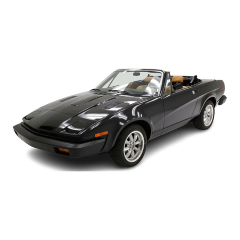
Triumph TR8 1980 User manual


~~
Published
by
I:,tJ
BL
Cars
Limited
Pub'M:.atOon
PIort
No.
AKM
4335
JAGUAR
ROVER
TRIUMPH
INC.
bOO
WILLOW
TREE
ROAD,
LEONIA
NEW
JERSEY
07b05

In alt
communicatIons
rel.llIng
to Service or Spares. pleasc
quotc
thc
CommiSSion
Numbcr
(ChassIs
Number
Ipaln\
and
,"m
numbers
Thesc
arc
stamped
on
a
plate
allachcd
to
Ihe
lelt-
and
door rear closing lace The CommiSSIon
Numbcr
IS
also
stamped
on
aplate
attached
to
the left·
hand
windscreen
plltar
and
IS
vIsible
through
thc
scrcen
Whcn
L.H.
or
A.H. is uscd
in
thc tCltt, this rcfers
10
thc
left-hand
or
Right-hand
of
the vchiclc.
vicwed
from
thc
driver's seat.
The
Manufactu.ers
rcserve the
IIghl
to
varv thcu specifications
wrlh
or
without
notice,
ar'd
al
such
IImcs
and
tn such
manner
as
Ihey thtnk fit
Major
as
wcll
as mlnOI
changes
may
be
Invol\cd
In
accordance
Wll the
Manulacturcr's
pohcy
01
conStant pr
uct
Improvcment
WhilSt every
effoll
IS
made
(0
ensure
Ihe
accuracy
of
paruculars
contained
III Hils Handbook, nClthcr The
Manufacturer
nor
the
Deater.
by
whom
thiS
Handbook
IS
supphed. shall
In
any
Clrcumstanccs
be
held !tablc
lor
any
,"accuracy
or the consequences
I
ereol
AU
fights
rcserved a
patl
of
thiS
publicatIon
may
by
repr
uced
Slorcd tn aretneval
systcm
or
transmitted
In any IOfm.
electroniC. rnecharucal. phOtOCopyrng,
record,"g
o. an
olher
means
wllhout
puo.
wflllen
permiSSion
Irom
the Se.",ce D,vISIon
of
Jaguar
Rover T
flwnph
2

Introduction
Controls.
Instruments
and
Indicators
Body Finings
Seats
and
Safety
Harness
Heating.
Ventilation
and
Air
Conditioning
Running
Instructions
Towing
II
Caravan
or
Trailer
Automatic
Transmission
Wheels
and Tyres
Cooling
System
Electrical
System
Care of Bodywork
CONTENTS
5
7
19
27
31
35
40
45
49
53
57
67
3

IMPORTANT
CAT
ALYTIC CONVERTER
SPECIFICATION
VEHICLES
The
TRB
IS
designed
to
operate
on UNLEADED fuels
of
91
octane
It IS essential that
only
unleaded
fuels are used
In
thiS vehicle otherWise
seriOUS
damage
can
1)8 caused
(0
the CatalytiC
Conv rter
Do not use oxygenated fuels such as blends
of
methanol/gasoline
or
ethanol/gasoline
Ie g G
SAHOU
4

INTRODUCTION
Now
that
you have taken delivery of your
new
car, please read this
Handbook
carefully to familiarize
yourself
with
the
controls
and
other
features,
which
have
been
deSigned for
yow
safety and
comfort
The lock key
number
IS
stamped
on the
lag
attatched
to
the larger
key
01
your key-sel, and
IS
nOI
5110wn
on
the key
or
lock
Please
make
a
record
at
thiS
number
as
you
will
need
It
to
obtain
a
replacement
Servicing
Before receiving your
new
car
II
Will have
undergone
an
Inspection
to ensure that all systems are workl11g and the vehicle
IS
complete
to specification,
After
completing
1000
miles
the vehicle
should
be
relurned
to the
seiling
Doaler
who
will
carry
out
the first
Important
service
and
make
whalever
adjustments
are
requl'ed
free of
charge
except
for
cost
of
lubricants
Subsequent
to
the
free
serVice,
maintenance
and
servICing
of
the
vehicle
IS
the
responSibility
of
the
owner
who
IS
adVised
to
make
lull
use
of
the
planned
maintenance
operated
by
all
Jaguar
Rover
Triumph
franchise
holders
The
opera
lions
carried
out
by
your
Dealer
Will
be
In
accordance
With
current
recommendations
and
rnay
be
subJectlO
revISion
from
time
to
lime
The
'Passport
10
Service'
which
Includes
the
'Owners
Service
Statement
has
prOVISIOn
for
the
Dealer
to
cortlfy
Ihal
the
work
has
been
performed
In
accordance
With
current
recommendations
Regular
use
of thePCissport
to
Service'
at
the
speCified
mtervals
IS
the
best
safeguard
against
the
pOSSibility
of
abnormal
repaIr
bills
at a
later
date
and
wOlild
constltll\e
proof
of
regular
serVICing,
thus
enhilnclng
the
value
of
your
car
10
a
prospective
buyer
Jaguar
Rover-Triumph
Inc.
Dealers are prOVided
wrth
the
laleSt
Information
cUllcernm9
speCial
lools
and
workshop
techniques.
enablmg
therll
to
undertake
your
service
and
repairs
mthe
most
eftlClent
andeconOlTllc
lllanTler

CONTROLS, INSTRUMENTS
AND
INDICATORS
Before
entering
the
vehicle:-
-
Check
that
the
windows
are
clean
and
visibility
is
not
impaired.
-Check
that
light
lenses are clean.
-
Check
lyres
for
condition
and
correct
pressure.
-Check
that
the
area
around
the car is clear
of
driving
hazards
before
driving
off.
-
Check
that
the
bonnet
and
boot
are
securely
closed.
On
entering
the
vehicle:-
-
Adjust
the
seats and head restraints.
-
Adjust
the
interior
and
exterior
(Door)
mirrors.
-
Fasten
seat
belts,
ensure
that
passengers
do
likewise.
-
Check
the
operation
of
light
switches.
horn
and
hazard
warning.
-
With
the
ignition
switched
on,
check
the
operation
of
all
warning
lights.
6

CONTROLS,
INSTRUMENTS
AND
INDICATORS
7

CONTROLS, INSTRUMENTS
AND
INDICATORS
CONTROLS
INSTRUMENTS
ANO
INOICATORS
Item
Description
Page
Ref
hem
Description
Page
Ref
Fascia
SldEl
venl
30
10 Glove box lock
20
2
CombinatIon
SWitch 13
II
Air
conditioning
healer
controls
?J
29
3
InSlrumems
and
warning
indicators
II
12
Air
conditiOning
cut·om
SWitch
28
4
Windscreen
wiper
and
washer
control
14 13
Instrument
l1um,nallon
rheostat
15
5
Master
Ilghlmg
SWitch
14 14 Gear selector lever
16
6
Heated
Rear Screen Swrtch
15 15
CIgar Ighler
15
7FasCIa
central
alf
vent
30
16 Pedals
16
8Fog
lamp
SWitch
15
17
Bonnel
release
cantrol
I.
•Hazard
warning
$wl1ch 15
8

"CONTROLS,
INSTRUMENTS
AND
INDICATORS
Fig. 1
12345 6 7 8 910 1
716 115 14 13 12
11
2339

CONTROLS,
INSTRUMENTS
AND
INDICATORS
Ignition/Starter
Switch
and
Steering
Lock
(Fig 2)
o
All
I
clrlcal
circuit
sWllched
olf
mechanical
lock
pr
-S
I
when
k y
IS
removed
1Auxill ry
posilion
2
Ignition.
3.
Start
Unlocking
Sequence
(clockwls
)
Insert
th key nlLirn I 0
posilion
'1'
If
Iftculty
IS
ncotln
ered, u n the se
fI
g
wheel
slightly
to
rheve
th
load
on
the
lock
boll
The
leering
wh
el h
uld
no
eIre
La
lurn
Fig.2
2333
10
This
operation
should
be
performed
only
after
the
following
requirements
have
been
carried
out
in
the
correct
sequence:-
1.
OCCUPANTS
SEATED; 2, DOORS CLOSED; 3.
SEAT BELTS FASTENED; 4, GEARS NEUTRAL. Refer
to
'Running
Instructions',
To SWitch
on
the
Ignition.
urn
the
key to OSIlion
'2'
urther
o e
nent
to pOSItion '3
opera
es
the
starter
motor
Th key
will
ret n0
position
'2'
wh
nreleas
Locking
Sequence
(an I
cI
c
WI
)T
rnlll
Lh
ey
irom
POSI
I
l'
'to'
'will
SWitch 0I
he
Inl Ion Pus th k YfL lIy
towards
he
10
and
Uf
I 0 OSIIIon
'0'
Withdraw
he e
and
mov
th st
erlng
wh
I
slightly
to sure
hal
lhe
lac
bol
IS
fully
engaged
WARNING.
If
for
any
reason
the
ignition
is
switched
off
while
the
car
is
in
motion
DO
NOT
ATTEMPT
TO
DEPRESS
OR
TURN
THE
KEY
TO
POSITION
'0',
as
this
constitutes
part
of
the
steering
lock
sequence,
The
designed
operating
sequence
prevents
the
engine
being
started
with
the
steering
LOCKED.
Serious
consequences
can
result
from
alterations
or
substitution
of
the
ignition
start
switch
which
would
permit
the
engine
to
be
started
with
the
LOCK
ENGAGED.
Under
no
circumstances
must
the
ignition
start
function
be
separated
from
the
steering
lock.

Speedometer
(Fig.
3)
Tile
speedometer
Indicates
the road
speed
of the
vehicle
In
miles
and
kilometres
per
hour,
It also
combines
the
following
indicators:
I1 )
Trip
odometer
-The figures
within
the
aperture
above
the
centre
of
the
dial
may
be used
to
record
the
distance
of
each Journey
provided
that
the figures are
pre-set
to
zero by
turning
clockWise the
knob
thai
extends
downwards
from
behllld
Ihe
IllS
ruments,
( 2 1
Odometer
-The figu rwlthlJl til
aperture
below
the
centre
of
tie
dial
records
the
lotal
mileage
of
lhe
vehicle and
may
eused as a
ulde
10
periodiC
lubrication
and
maintenance
Tachometer
(Fig,
31
The
tachometer
Indicates
the
englll
speed
In
revolutions
pel
minute
and is
calibrate
III
Incr menlS
of
500,
eXlendlngo
7,000
r,p.m
Recommendations
concerning
til
speed
range are give
under
'Running
InSlrUClions'
Warning
Lights
(Fig 3)
13)
Oxygen
Sensor
(PI
vehicles
onlyl
The Oxygen Sensor
Indicator
glows
wen the
sensors
require
renewal.
ThiS Will
occur
Ithe
mileag
Interv I
staled
III
the
Maintenance
Handbook
Consult
your
dealer
as
soon
as
convenl
nt <lfler
tile
Indlcalol
ilium
Ina
les
The IildlCalOr
glows
when
he
starter
motor
IS
operated,
failure
to
do so
Indlcat
s
bulb
failure,
CONTROLS,
INSTRUMENTS
AND
INDICATORS
Fig,3
and
(S)
Direction
indicaror
monitors
-The
arrow
In
IcalOr
(4)
glows
green
Intermittently
wh
nthe
steerlll
column
combillation
sWllch
IS
1110V
10
Signal
a
lefl-hand
lUI
nThe
In
Icatol
(5)
glows,
Ii1arly
wh
n
the
SWI
ch
IS
Illoveclto
Signal a
rl
ht-hand
turn
( )
Not
used
on
US
vehicles
(
7)
Ignition
.-
The
'Ignition'
mdicalor
glows
red
when
the
IIlltlOn
IS
sWllche on an
IS
extln
ulshed
when
til
erlgillp.
IS
rllllnln(
18 1Oil
pressure
-Thp
'all'
Indicator
glows
when
th
I
/lIlian
IS
SWitched on
and
IS
extlllgulsiled
wilen
the
8nglne
IS
runnrn~J
11

CONTROLS,
INSTRUMENTS
AND
INDICATORS
Fig,4
,",
,
~
( 9 I
Brakes
-
Should
I
dure
of
the
Iront
01
leal
hydraulic
brake
lines
occur.
the
Inellcarol Will
glow
The
causl'
mUSt e
recti
led
Imm
dlately.
The
system
IIlcorporales
a
ul
tesl
faclllly
I
hl'
Indicator
should
glow
w
len
[he
staner
motor
I
operated,
failure
to
do
so
Indicates
a
Bulty
bulb
110)
Belts
-
The
'Belts'
Inellcator
will
glow
for
approx-
Imately
ten
secon
s
when
the
engine
IS
s
aned
If
the
nv
r
has
not
fas
ened
hiS
seat
el
This
will
b
accompanied
by an
audible
alarm
If t e
driver
astens
hiS
seat
bIt
before
starlin
the
engllle,
the
IIldrcaiQr
will
glow
wltlloUt
the
audible
warning
R
fro
'R
unnlng
Instructions'
and
{51
Direction
indicator
monitors
-
The
arrowed
IndlCaLOr
14)
glows
green
lIliermlilemly
wilen
the
slDerlllg
column
com
Inatlon
SWlich
IS
moved
to
51
nal
a
lell-hand
lurn
The
Indica
lOr
(5)
glows
slInllarly
when
the
sWllch
IS
moved
to
Sl
/lal
IghHland
turn
1131
Main
beam
-
Ttle
'Beam'
IIldlcator
glows
blue
\her.
main
)8amS
.r
selected
and
IS
eXiingUished
durlllg
dipped
flear
op
ra
Ions
1141
Fuel
-Th
ue
mdlc
lor
glows
whe
the
quantity
of
uIIn
the
lank
ails
below
6 8 I tres
(1
5
g'
1I0nsi Fuel
sur
e
may
c
us
he
In IC lOr to
glow
Inl
rmll[
Illly
before
the
luells
redllc
dlO
IllS
iJiTlOU
l
Warning
lights
(Fig
4)
The
warlllllg
II
hI
layout
on
ear
II
er
veillci
S
IS
13)
Main
beam
The
'Beam'
Illdlcator
lows
blu
when
ma
nl)e8ll1lS r
selecled
anel
IS
extingUIshed
dllllllg
dipped
beam
0era Ion
141
11
II
Park
Brake
-Tile
palk
bra
eIlleilcalOr
glows
when
Ihe
IlarJ(ibra eIS
applied
an
the
Ignltloll
IS
sWitched
Oil
112)
Coolant
-The
Coolant
In
IcalOr
glows
when
he
coolant
level
III
Ihe
header
lank
IS
100
low
The
laull
Siloulci be
lectlfled
Immedla
ely by to
plllg
up
tile
header
lank
10
I~le
recomrn
nd
dillS
rUCliOIl
Ipage
551
A
prudollt
watch
Slloulcl
be
kept
all th
coolan
I
mper
lur,
g
uge
to
ensure
hal
he
ngln
cia snOI
overheat
The
1/)(JICiJIOI
glows
or Ihr ee
seconds
when
the
II
'l1l10n
IS
SWitched
on,
farlur 10 clo
so
nOlcales
l)u111
fallu "
•
~
• • I _
-'
..
,:
231.8
-:;,-
)
12

1
6)
Demist
~
The
Demlst
indicator
glows
when
lhe
real
screen
element
1$
sWitched
on
17)
Ignition
~
The
'Ignition'
Indicator
glows
red
when
the
Ignition
IS
sWitched
on
and
IS
extinguished
when
the
engine
IS
runnlnq
{
8)
Oil
pressure
~
The
'Oil'
mdlcator
glows
when
the
Ignition
1$
sWitched
on
and
IS
extinguished
when
the
engine
IS
runnmg
(9
1
Brakes
~
Should
failure
of
the
front
or rear
hydraulic
brake
Imes
occur,
or If
lhe
handbrake
IS
left
'on'
the
Indicator
Will
glow
It
the
lamp
glows,
mdlcatlng
f8llwe
of
lhe
hydrauliC
system,
the
cause
must
be
rectified
Immediately
The
IndlcalOr
should
lIummate
wIlen
the
starler
motor
IS
operated.
fallule
to d
so
Indicates
bulb
failure
{101
Belts
~
The
Seat
BI'lt
warning
light'
Will
glow
when
the
Ignition
IS
SWitched
on
and
a
vehicle
occupant
has
nOl
fastl'ned
aseat be tThl$
will
be
accompanied
by
on
iludlble
alarm
Refer
10
Running
Instructions'
(1
1)
Not
used
on
USA
vehicles
CONTROLS, INSTRUMENTS
AND
INDICATORS
112) Fuel
~
The
Fuel
indiCator
glows
when
the Quantity
01
fuel
In
the
tank
falls
below
68
Illres
11
5
gallons
IFuel
sUlge
may
cause
lhe
indicator
to
glow
Interrnlttently
before
Ihe
fuel
IS
reduced
to lhlS
amount
{131
Fog
(optional
fllment)
~
If
the
vehicle
IS
equlppod
with
fog
lamps,
the
Indicator
Will
gtow
when
the
CHCUIt
IS
operative
(14)
Not
used
on
USA
vehicles
13

CONTROLS. INSTRUMENTS
AND
INDICATORS
Fig. 5
14
Clock
(Fig
51
The hands
of
the electrically
operated
clock can be reset by
turning
the knob
localed
below
the
Instrument
and extending
from
the
lower
fascIa
rail
Water
Temperature
Indicator
(Fig
51
The gauge IS marked
'C
(cold) and -H'
(holl.
Indicating the
temperature
at
the
coolant
as
It
leaves
the
cylinder
head
I\IS
efleclive
when
the
Ignilion
IS
sWitched
on
When
the
Ignition
IS
switched
off
the needle should return to
zero
Fuel
Gauge
(Fig
51
The
gauge
mdicates
the
contents
of
the
fuel
lank
Allow
thirty
seconds for the gauge needle to reach asteady reading after
sWitching
on
the
19n1llon
When
the
Ignition
IS
sWl1ched
off
the needle
should
return to
zero
Voltmeter
IFlg
5)
The
voltmeter
registers
the
bal1ery"s
state
of
charge
if
the
gauge
registers
In
the
lower
reel
sector
under
normal
running
conditions.
the
cause
should
be
Investigated

Combination
Switch
(Fig
6)
he s(.erln9-
umn
combma
tOn
sw,
ch
s r es he
0110
Ing
purpos
S
Horns
-T
ope
a e
he
horns
pr
ss
en
0 . e
control
CONTROLS.
INSTRUMENTS
AND
INDICATORS
Fig.6
2332
Fi
.7
Wind
creen
Wiper
and
Washer
Control
(1"19
7)
Tl
control
IS
ell
CLIVe
only
wh
nIh
Ignition
IS
SWIIC
eel
on
For
continuous
operation
a
lh
wo
sp Wipers,
move
h
con
rol
Ilpwards
0
posi
Ion Ifor
low
speed
operation.
or
ully
upwar
s\0
POSI
Ion
2'
lor
hIgh
sp d
operatlor
For
bnef
use 0h
wipe.
move
he
con
rol
downwards
agems
s
f1ng
pr
ssur
W,p
ng
will
cees
en'
eCOnt'O
IS
re eased
s'e
00
h
229
15

CONTROLS,
INSTRUMENTS
AND
INDICATORS
Fig.8
12 3 4
1587
Master
Lighting
Switch
/1
Fig
8)
r (
la~e
Ine'
r
ern
lighting
SWI
eh
uppe
POSI
Ion
'0
II
o
tle
0
and
adllarrlps a(I Illu
ar
r
If
the
headlamp
Ii
mechanism
ails
0raise
he
headlamps,
refer
to
'Elecirical
Sys
em
-
Headlamps.
Heated
Rear
Screen
Switch
~2,
FI
8)
Mav'
hSWllch
11fl1
0he
lower
POSI
1011
to 081
al
Illl'
healed
rar screen,
which
Will
operale
only
when
[h IlJrllllon
IS
sWitched
'ON'
A
lamp
IIlcorporated
III
th ,
sWitch
will
illuminate
willi
tile
h
at-r
IS
operating
Do
no
eav sWlLched 0
or
longer
han
IS I
flCt'S
eca
se
0'
heavy
curr
nt
cor
su
ptton
T:'."" cOFF' ._I
al
-0
;ne
upper
)Sltlon
The
hea
er
should
no
be
used
0
remove
snow
or
ice.
bu
may
be
used
periodically
0
emove
condensa'ion
or
0
prevent
ice
ormation.

Fog
Lamp
Switch
lwhere
fill
d) (3, Fig 8)
Movo
lhe
sw
lch
bar
to the
mid
POSI
Ion
0
illuminate
ihe
rear
og
guard
lamps
only
Move
he
SWI
eh
bar
10
lh
lower
pOSlllon
to
illumlna
ne
ronl
an
rear
og
lamps
Move
h
SWI
ch
i'lf
[0
lhe
upper
POSI
Ion
La
e
llngUish
lhe
lamps
A
arnlng
famp
lncorpora'
dIn
.he
s.
Itch
will
ilium
nate
wmle
the la p
ClrCUI
IS
SWI
hea
0
Instrument
Illumination
R
eostat
See
aster
L,g
1119
Sitch'
CONTROLS,
INSTRUMENTS
AND
INDICATORS
Cigar-lighter
(2, Fig 9)
The
cigar
II
hler
is
operated
y
pushing
ItS
knob
Inwards
La
heal
the I
ment
Wilen
a
pr
determined
emperalure
IS
reached.
the
element
IS
elec
ed
frOITl
he
hea
POSI
Ion
from
whence
I
may
e
WI
hclrawn
or
use
A
small
pllOL
lamp
IS
Ir1corporal,d
WI
hm
[he
alemen
carner
a
facilitate
rep
ac
men
01
lhe
lement
dur
ng
darkness
17

CONTROLS,
INSTRUMENTS
AND
INDICATORS
Fig
10
9
lIgn;s
-ag
'1
Gear
Selector
Lever
(Fig
10)
-I-je gear 0
,;,
Ins are
nd
ca e
on
he Ie 'er
nob
Engage
re.ers
onl
hen
lee
Iele
IS
saIOnary
Au'oma'lc
rans ISSlon seJeclor
cie
a
Is
are
g n nsec Ion
-
'80rg-
arner U
oms'le
Tra smlSSlor
For
00
Imu
uel
econom
he
recommended
g
ar
change
speeds are
1s
2nd
15
111
P h
2nd/3rd
-
25
mph
3rd/4th
40
m
,11
4th/5th
-
45
III
P h
Pedals
-he
peda,s are
arranged
n
he
convem
anal
pOS
Ions
T e
ra e
pedal
operates
the brake hyd aulcsyslem
to
apply
he
brakes
on
<
II
four
wheels
Warning
lie
hiS
ai
ih
rear athe
vehlele
function
auoilla
IC
Ily
when
the bra eedal
IS
press d
while
hIgnition
IS
SWitch don 0
aVOid
nedless
wear
of
th
clutch
wlthdr
wal m
.chanisill.
do
not
rest
lhe
rom on
th
ellJ
eh pedal
whd
driVing
Re'er 0
5
I
.',,'
2073
J
:,:'
I
".
8

Always
remember
to
lock
your
car
when
leaving
it.
The
lock
key
number
is
stamped
on
the
tag
attached
to
the
larger
key
of
your
key-set,
and
is
not
shown
on
the
key
or
lock.
Please
make
a
record
of
this
number
as
you
will
need
i
to
ob
ain a
replacemen
.
~
/
BODY FITIINGS
Table of contents
Other Triumph Automobile manuals

Triumph
Triumph TR3 User manual

Triumph
Triumph Spitfire MK3 User manual

Triumph
Triumph TR7 User manual

Triumph
Triumph TR4 Instruction manual

Triumph
Triumph TR7 User manual

Triumph
Triumph TR6 PI User manual

Triumph
Triumph TR8 User manual

Triumph
Triumph TR6 1976 User manual

Triumph
Triumph TR6 Trophy Operating instructions

Triumph
Triumph 1800 1951 User manual

Triumph
Triumph TR6 1969 Manual

Triumph
Triumph TR4 User manual

Triumph
Triumph TR4A User guide

Triumph
Triumph TR2 Operating instructions

Triumph
Triumph Dolomite Sprint User manual

Triumph
Triumph TR4 User guide
Triumph
Triumph TR2 User manual

Triumph
Triumph MAYFLOWER 1951 User manual

Triumph
Triumph 1961 TR4 User manual
Triumph
Triumph TR6 Trophy User manual