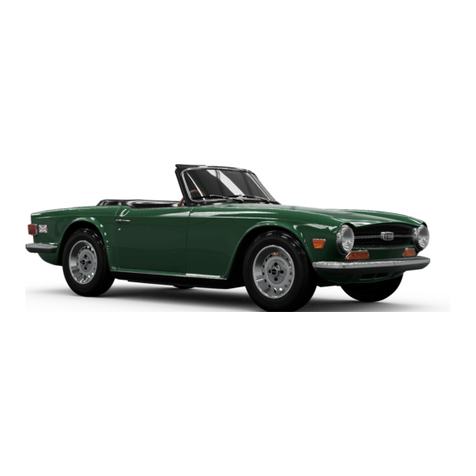
Triumph TR8 User manual


~~
Published
by
~
BL Cars
Limited
Puble.tion
hrt
No.
AKM
4335
JAGUAR
ROVER
TRIUMPH
INC.
600
WILLOW
TREE
ROAD,
LEONIA
NEW
JERSEY
07605

In all communIcatIons
relallng
to
Service or Spares. please
quote
thc
CommISSion Number (ChassIs Number Ipaint and
lrlm
numbers These
arc
stamped
on
aplate allached
to
the left-hand door rcar closing face The CommISSion Number
IS
also
stamped
on
aplato
anached
to
tho leh-handwindscreen pIllar and
IS
vIsible through the screen
When
L.H.
or
R.H. is used
in
the
texl.
Ihis
refers
10
the
Left-hand
or
Right-hand
01
the vehicle.
viewed
from
Ihe
driver'sseat.
The Manufacturers reserve the rrght
to
vary theIr speCifications
wIth
Of
without
nOtice. and at
such
limes
and
In
such manner as
they thmk fll
Major
as
well
as
minOt changes may
be
mvolved maccordance
with
Ihe
Manufacturer's
polley
of
constant produCI
Improvemenl
Whilst
every efforl
IS
made
to ensure the accuraey
of
patllculars contained In
thIS
Handbook. neIther The Manufacturet nor the
Dealel.
by
whom
Ihls
Handbook
IS
supplied. shall many CIrcumstances
be
held liable lor any maccuracy or
the
consequences
thereof
All
IIghlS reserved
No
parI
of
Ihls publication may
by
reproduced. Slored m a retrIeval SVslem or
Iransmlued
In any 10fm.
clCCltomc. mechamcal.
phOtOCOPVrng.
recordrng or any other means wllhOut
pllor
wlIl(en
permISSIon
ftom
lhe ServIce
DIVISIon
of
Jaguar Rover TrIumph
2

Introduction
Controls,
Instruments
and
Indicator.
Body Fittings
Seats
and
Safety
Harness
Heating.
Ventilation
and
Air
Conditioning
Running Instructions
Towing
aCaravan or
Trailer
Automatic
Transmission
Wheels
and Tyres
Cooling
System
Electrical
System
Care
of
Bodywork
CONTENTS
5
7
19
27
31
35
40
45
49
53
57
67
3

IMPORTANT
CATALYTIC
CONVERTER
SPECIFICATION
VEHICLES
The
TRa
IS designed
to
operate
on UNLEADED fuels of 91 octane
It
IS
essential that only unleaded fuels are used
In
this vehicle otherwise
seriOUS
damage
can be caused
10
the CatalytiC
Converter
Do not use oxygenated fuels such as blends
01
methanol/gasoline or ethanol/gasoline
(e
gGASAHOL)
unEADfD
FUEl
ONLY
2335
4

INTRODUCTION
Now
that
you have taken delivery
of
your
new
car, please read this
Handbook
carefully
to
familiarIZe
yourself
with
the
controls
and
other
features,
which
have
been
designed
tor your safety and
comfort
The lock key
number
IS
stamped
on
the tag
attatched
to the
larger
key
of
your key-set. and
IS
nol
shown
on
the key
or
lock
Please make arecord
of
this
number
as you
will
need It to
obtain
a
replacement
Servicing
Before receiving your
new
car
It
will
have undergone
an
Inspection
10
ensure that all systems are working and the vehicle
is
complete
to specification,
After
completing
1000
miles
the vehicle should be returned to the seiling Dealer
who
will carry
out
the first
Important
service
and make
whatever
adjustments
are
requl'ed.
free
of
charge
except for cost
of
lubricants
Subsequent
to the free serVice,
maintenance
and servICing
of
the
vehicle
IS
the responSibility
of
the
owner
who
IS
advised to
make full use
of
the
planned
maintenance
operated
by all
Jaguar
Rover-Triumph franchise holders TI,e
operations
carned
out
by
your Dealer
will
be
In
accordance
With
current
recommendations
and
may
be
subject
to revIsion from
time
to
time
The 'Passport
to
Service'
which
Includes
the
'Owners
Service
Statement'
has provISion for the
Dealer
to certify that the
work
has
been
performed
In
accordance
With
current
recommendations
Regular use
of
the 'Passport
to
Service' at the specified Intervals
IS
the best safeguard
against
the
possibility
of
abnormal
repair bills at alater
date
and
would
constl\i)te
proof
of
regular serVICing,
thus
enhanCing the value
of
your
car
to
aprospective buyer
Jaguar
Rover-Triumph
Inc.
Dealers
are prOVided With the latest
Information
concerning
special
tools
and
workshop
techniques.
enablmg
them
to
undertake your service and repairs
IfI
the
most
effiCient and-economiC
manner
5

CONTROLS, INSTRUMENTS
AND
INDICATORS
Before entering the vehicle:-
-Check
that
the
windows
are clean and visibility is
not
impaired.
-Check
that
light
lenses are clean.
-Check tyres for condition and correct pressure.
-Check
that
the area around the car
is
clear
of
driving hazards before driving off.
-Check
that
the
bonnet
and
boot
are securely closed.
On
entering the vehicle:-
-
Adjust
the
seats and head restraints,
-Adjust the interior and exterior (Door) mirrors.
-Fasten seat belts, ensure that passengers do likewise.
-Check
the
operation
of
light
switches,
horn and hazard
warning.
-
With
the
ignition
switched
on, check the
operation
of
all
warning
lights.
6

CONTROLS, INSTRUMENTS
AND
INDICATORS
7

CONTROLS, INSTRUMENTS
AND
INDICATORS
CONTROLS
INSTRUMENTS
ANO
INDICATORS
Item
Description
Page
Ref
Item
Description
Page
Ref
FasCia
side
vent
30
10
Glove box lock
20
2
Combination
sWitch
13
11
Air
conditioning/heater
controls
2J-29
3
Instruments
and
warnmg
indicators
11
12
Air
conditioning
cut-out
sWitch
28
4
Wmdscreen
wiper
and
washer
control
14 13
Instrument
IllUminatIOn
rheostat
15
5
Master
lightmg
sWitch
14
14
Gear selector lever
16
6
Heated
Rear Screen SWllch
15 15
Cigar
lighter
15
7FasCia
central
air
vent
30
16
Pedals
16
8Fog
lamp
SWitch
15 17
Bonnet
release
control
19
9Hazard
warnmg
switch
15
8

CONTROLS. INSTRUMENTS
AND
INDICATORS
Fig, 1
12345 6 7 8 9
<
10
-.
,,_
....
1
17
16
11
15 14
13 12
11
2339
9

CONTROLS, INSTRUMENTS
AND
INDICATORS
Ignition/Starter
Switch
and
Steering
Lock
(Fig. 2)
oAll electrical Circuits
sWitched
off mechanical lock pre-set
when
key
IS
removed
1Auxiliary
position
2
Ignition
3Start
Unlocking
Sequence
(clockwlse~
Insert the key and turn
1110
POSition '1" If
difficulty
IS
encountered,
turn
the
steering
wheel
slightly to relieve
the
load
on
the lock
bolt
The
steermg wheel should
now
be free
to
turn
This operation should be
performed
only
after the
following
requirements
have
been
carried
out
in
the
correct
sequence:- 1. OCCUPANTS SEATED;
2.
DOORS CLOSED; 3.
SEAT BELTS FASTENED; 4. GEARS NEUTRAL Refer to
'Running
Instructions',
To
sWitch
on
the
Ignition,
turn
the
key
to
POSition
'2'
Further
movement
to posItion
'3'
operates
the starter
motor
The key
will
return to POSition
'2'
when
released
Locking
Sequence
(anti-clockwise) Turning the key from
POSition
2'
to
"
will
SWitch
off
the
Ignition
Push the key fully
towards
the lock and turn
It
to POSition
'0'
Withdraw
the key
and move the steenng
wheel
slightly
to
ensure
that
the lock
bolt
IS
fully engaged,
WARNING,
If
for
any
reason
the
ignition
is
switched
off
while
the
car
is
in
motion
DO
NOT
ATTEMPT
TO
DEPRESS OR
TURN
THE
KEY
TO
POSITION
'0',
as
this
constitutes
part
of
the
steering
lock
sequence.
The
designed
operating
sequence
prevents
the
engine
being
started
with
the
steering
LOCKED,
Serious
consequences
can
result
from
alterations
or
substitution
of
the
ignition
start
switch
which
would
permit
the
engine
to
be
started
with
the
LOCK
ENGAGED.
Under
no
circumstances
must
the
ignition
start
function
be
separated
from
the
steering
lock,
B-o
i~~
\
2
Fig.2
2JJJ
10

Speedometer
(Fig. 3)
The
speedometer
indicates the
road
speed
of
the
vehicle
In
miles
and
kilometres
per hour. It also
combmes
the
following
indicators
1 1 )
Trip
odometer
~
The figures
within
the aperture above
the centre
of
the
dial
may be used
to
record the
distance
of
each
journey
provided that the figures are
pre-set to zero by
turning
clockwise
the knob that
extends
downwards
from
behind
the
Instruments,
( 2 )
Odometer
-The
figure
within
the aperture
below
the
centre of the dial records the
lola
I
mileage
01
the
vehicle and
may
be
used
as
agUide to periodic
lubrication
and
maintenance.
Tachometer
(Fig,
3l
The
tachometer
indicates
the
engme
speed
In
revolutions per
minute
and
IS
calibrated
In
Increments
of
500.
extendmg
to
7,000
rpm,
Recommendations
concerning
the speed range are given
under
'Runnmg
Instructions'
Warning
lights
(Fig
3l
(
3)
Oxygen
Sensor
(PI
vehicles onlyl
The Oxygen Sensor
Indicator
glows
when
the sensors
require
renewal
ThiS
will
occur
at the
mileage
mterval
stated
In
the
Maintenance
Handbook
Consult your
dealer as soon
as
convenient after the
mdlcator
illuminates
The
indicator
glows
when
the starter
motor
IS
operated,
failure
10
do
so Indicates
bulb
failure
CONTROLS, INSTRUMENTS
AND
INDICATORS
Fig. 3
61
•
)
)
,,,,' ','"
(4)
and
(5)
Direction
indicator
monitors
-The arrowed
indicator
(4)
glows
green
Intermlllently
when
the
steering
column
combmatlOn
switch
IS
moved
1O
Signal
a
lell-hand
turn The
Indicator
(5)
glows
Similarly
when
the
switch
IS
moved
to Signal a
right-hand
turn
(
6)
Not
used
on
USA
vehicles
( 7 l
Ignition
"T"""
The
'Ignition'
Indicator
glows
red
when
the
Ignition
IS
SWitched on
and
IS
extinguished
when
the
engine
IS
running
(8
IOil pressure -The
'Oil'
indicator
glows
when
the
Ignition
IS
SWitched on
and
IS
extinguished
when
the
engine
IS
running
11

CONTROLS, INSTRUMENTS
AND
INDICATORS
(9
l
Brakes
-
Should
failure
01
the
front
or
rear
hydraulic
brake lines
occur,
the
indicator
will
glow
The cause
must
be
rectified
Immediately
The
system
incorporates
a
bulb
test
facility
The
Indicator
should
glow
when
the
starter
mOlar
15
operated, failure
10
do
so
indicates
afaulty
bulb
110)
Belts
-The
'Belts'
indicator
Will
glow
for
approx-
Imately
ten
seconds
when
the
engine
IS
started
If
the
dnver has
not
fastened
hiS
seal
bell. This
will
be
accompanied
by an
audible
alarm, If
the
dnver
fastens
hiS
seat
belt before
starting
the engme, the indicatOr
will
glow
without
the
audible
warning
Refer to
Runnmg
Instructions'
Fig,4
6 1
td:a
)
)
12
9
(11)
Park
Brake
-The
park
brake
Indicator
glows
when
the
handbrake
1$
applied
and
Ihe
Ignition
IS
sWitched
on
(12)
Coolant
-
The
'Coolant"
Indicator
glows
when
the
coolant
level m
the
header
tank
IS
tOO
low
The
fault
should
be
rectified
Immediately
by
toppmg
up
the
header
tank
10
the
recommended
II1structlon
(page
551
A
prudent
walch
should
be
kept
on
the
coolant
temperature
gauge
to
ensure
that
the
engme
does
nOI
overheat
The
Illdlcator
glows
for
three
seconds
when
the
I~""lltlon
IS
sWitched
on,
failure
to
do
so
Illdlcates
bulb
fallu
~
113)
Main
beam
-
The
'Seam"
Illdicator
glows
blue
when
malll
beams
are
selected
and
IS
extingUished
dUfing
dipped
beam
operations
(141
Fuel
-
The
Fuel
mdlcator
glows
when
the
quanllty
of
fuel In
the
tank
lalls
below
6 8 htres
(1
5
gallonsl
Fuel
surge
may
cause
the
Illdlcator
to
glow
Intermittently
before
the
fuel
IS
reduced
to
thiS
amount
Warning
lights
(Fig 4)
The
warnlllg
light
layout
on
earlier
vehicles
IS
(3)
Main
beam
-The
'Beam"
Illdlcator
glows
blue
when
malll
beams
are
selected
and
IS
extingUished
durlllg
dipped
beam
operation
(41
and
(51
Direction
indicator
monitors
-
The
arrowed
Indicator
14)
glows
green
Illterml11ently
when
the
steering
column
combination
SWitch
IS
moved
to
signal
a
left-hand
turn
The
indicator
(5)
glows
Similarly
when
the
SWitch
IS
moved
to
signal
a
fight-hand
turn

16)
Demist
-The
'Demist'
indicator
glows
when
the rear
screen element
1$
sWitched on
17)
Ignition
-The
'Ignillon'
Indicator
glows
red
when
the
Ignition
IS
sWitched
on
and
is
extmguished
when
the
engine
IS
running
(
8)
Oil
pressure
-The 'Od'
mdlcator
glows
when
the
Ignition
1$
switched
on
and
1$
extinguished
when
the
engme
1$
running
(9
lBrakes -Should failure
of
the front or rear hydraulic
brake Imes occur, or
if
the handbrake
IS
left
'on'
the
Indicator
will
glow, If
the
lamp
glows.
indicating
failure
of
the hydrauliC system, the cause
must
be rectified
Immediately
The
Indicator
should
Illuminate
when
the
starter
motor
IS
operated.
failure
10
do
so
Indicates
bulb
failure
(101 Belts -The 'Seat
Bell
warning
light'
will
glow
when
the
Ignition
IS
SWl\ched
on
and avehicle
occupant
has
not fastened aseat
belt
ThiS
will
be
accompanied by
an audible alarm Refer to 'Runnmg Instructions'
(1
1)
Not
used
on
USA
vehicles
CONTROLS, INSTRUMENTS
AND
INDICATORS
(12)
Fuel -The Fuel
mdicator
glows
when
the
quantity
01
fuel
In
the tank falls
below
68
litres
(1
5gallonsl Fuel
surge may cause the
mdlcator
to
glow
intermittently
before the fuel
IS
reduced to thiS
amount
(131
Fog (optional
fltmentl
-If the vehicle is eqUipped With
fog lamps, the mdlcalOr Will
glow
when
the
CirCUit
IS
operative
(14)
Not
used on USA vehicles.
13

CONTROLS, INSTRUMENTS ANO INDICATORS
Fig.5
.=
,·=e
••
"'"
14
Clock (Fig 5)
The
hands
of
the electrically
operated
clock can be resel by
turning
the knob located
below
the
Instrument
and extendmg
from the lower fascia rail
Water
Temperature
Indicator (Fig 5)
The
gauge
IS marked 'C' (coldl and
'H'
(hot), Indicating the
temperature
of
the
coolant
as
Illeaves
the cylinder head. It
IS
effective
when
the
Ignition
IS
sWitched
on
When
the
Ignl\lon
IS
switched
off
the needle should return to
zero
Fuel
Gauge
(Fig, 5)
The gauge indicates
the
contents
of
the
fuel tank
Allow
thirty
seconds for the gauge needle to reach asteady readmg after
SWitching
on
the
Ignilion.
When
the
Ignilion
IS
sWl1ched
off
the needle
should
return to
zero
Voltmeter
(Fig, 5)
The
voltmeter
registers the battery's state
01
charge. If the
gauge registers
In
the lower red sector
under
normal
running
conditions. the cause should be Invesllgated,

CONTROLS, INSTRUMENTS
AND
INDICATORS
Fig, 6
Combination
Switch
(Fig.
6)
The
steenng-column
combination
SWitch serves
the
following
purposes
Horns -To operate
the
horns. press the
end
of
the
ccnlrol
Direction
indicators
-To
Indicate
aleft-hand turn.
move
the
lever
anll-clockwlse
Move
It
clockwise
for
a
fight-hand
turn
This
control
IS
only
effective
when
the
Ignillon
IS
switched
on
Headlamp
main
beam
-To operate
the
main
beams. push
the
lever fully
forward
away
from
the
steeflng
wheel. Pull
the
lever
10
liS
neutral
(centrall
pOSl1lcn
for
dipped
beams
This
control
IS
only
effective
when
the
'master
lighting
sWitch"
IS
moved
to
the
headlamp
position
Windscreen
Wiper
and
Washer
Control
{Fig
7l
The
centrollS
effective only
when
the Ignll10n
IS
sWitched
on
o
or
:::::J=
2332
Fig. 7
For
continuous
OperallQn
of
the
two
speed
Wipers,
move
the
control
upwards
to
position
'"
lor
slow-speed
operation,
or
lullv
upwards
to
poSItion
'2-
for
high-speed
operatIOn For
brlel
use
01
the
Wiper,
move
the
control
downwards
against
spong
pressure
Wlpmg
WIll cease
when
the contrOl
IS
released
To
operate
lhe
windscreen
washer,
press the
knob
on
Ihe
end
ollhe
control
""
15

CONTROLS, INSTRUMENTS
AND
INDICATORS
Fig. 8
16
Master
Lighting
Switch
(1. Fig
8)
To
operate
the
three-position
lighting
sWitch
•
Move
the
switch
bar to the
upper
position
to
extinguIsh all
external
and
fascIa
lamps
-
Move
the
sWllch
bar
10
the
mid
paSHlon
to
Illummate
front
and
rear
parkmg
and
marker
lamps
and
the
faSCia
lamps
•
Move
the
sWItch bar to
the
lower
poSllIon
to raIse
and
Illummate
me
headtamps
and
Illummate
the
parking,
marker
and
lascla
lamps
If
the
headlamp
lift
mechanism
fails
to
raise
the
headlamps,
refer
to
'Electrical
System'
-
Headlamps.
Heated
Rear
Screen
Switch
(2. Fig 8)
Move
the
SWitch
bar
to
the
lower
POSition
10
operate
the
heated
reaf
screen,
which
Will
operate
only
when
the
Ignition
1$
sWllched
·ON·
A
lamp
Incorporated
In
[he SWitch Will
Iliummate
while
the
heater
IS
operating
Do
not
leave sWitched
'ON'
10f
longer
than
IS
necessary
because
of
heavy
current
consumption
•
To SWitch 'OFF'
move
the
SWitch
bar
to
the
upper
pOSlllon
The
heater
should
not
be
used
to
remove
snow
or
ice, bUI
may
be
used
periodically
to
remove
condensation
or
to
prevent
ice
formation.

Fog
Lamp
Switch
(where
fitted}
(3, Fig
8)
Move
the
SWitch
bar
to
the
mid
POSition
10
Illuminate
the
rear
fog
guard
lamps
only
Move
the
SWitch bar
\0
the
lower
position
to
Illuminate
the
front·and rear fog lamps
Move
the SWitch bar to
the
upper
POSition
10
extingUish the
lamps
A
warning
lamp
Incorporated
In the
$wllch
will
Iliummate
while
the
lamp
CirCUlI
15
SWitched 'ON"
This
CIrCUIt
15
operative
only
when
the
Side/tail
lamps
are
Illummated
The
warning
light
IS
Incorporated
In
the
Instrument
panel
on
earlier vehIcles Reier
10
Warning
LIghts
Hazard
Warning
Switch
(4.
Fig
8)
If
the
vehicle
IS
Immobilized
and
constitutes
ahazard
to
other
road
users.
warning
may
be
gIVen
by
uSing
the
'hazard
warmng
system'
To
operate
move
the
SWitch bar to the lower
position
Instrument
Illumination
Rheostat
(1.
Fig
91
From
the
'OFF
poSitIon (fully
ani
I-clockwise!.
turn
Ihe
swllch
!moh
clockwise
to
Ilium
InaIe
the
Instruments
at
low
intensity.
i1nd further clockWise
10
Increase
the
intensity
See
'Master
l.ghtlng
SW!lch'
CONTROLS. INSTRUMENTS
AND
INDICATORS
Cigar.lighter
12,
Fig 9)
The
cigar-lighter
IS
operated
by
pushing
Its
knob
Inwards
10
heal
the
element
When
a
predetermined
temperature
IS
reached,
the
element
.s ejected
from
the
'heal'
position
from
whence
It
may
be
wl\hdrawn
for
use A
small
pilot
lamp
IS
Incorporated
within
the
element
carrier
to
faCilitate
replacement
of
the
element
during
darkness
Fig. 9
17

CONTROLS, INSTRUMENTS
AND
INDICATORS
Fig_
10
Refer to
Warning
Lights' -
page
11
Handbrake
lever
{Fig 11)
To applv the rear
wheel
brakes.
pull
the
handbrake lever
upwards.
II
1$
retained by a
ratchet
and
pawl
Release
the
hand brake by
pulling
It
slightly
upwards
as
the
bullon
IS
depressed
10
free
the
pawl.
then
allow
the
lever
to
move
downwards
to the
off
posltlQn
Gear
Selector
Lever
(Fig.
101
The gear poSitions are Indicated
on
the
lever knob Engage
reverse
only
when
the vehicle
1$
stationary
Automatic
lransmiSSlon
selector details
are
given
In
sectIOn
-
'Borg-Warner
AutomatiC
TransmiSSion"
For
optimum
fuel
economy
the
recommended
gear
change
speeds are
lst/2nd-15
mph
2nd/3rd •25 mp,h
3rd/4th
-
40
mp,h
4th/5th
-
45
mph
Pedals
The pedals are arranged
In
the
convenllonal POSItions The
brake pedal operates the brake hydraulic system to apply
the
brakes
on
aU
four
wheels
Warning
lights at the rear of
the
vehicle function automatically when the brake pedal
IS
pressed
while
the
igmllon
IS
sWitched on
To
aVOid
needless
wear of the
clutch
withdrawal
mechanism.
do
not rest the
toot
on
the
clutch
pedal
while
driVing
5
4
\\
J
'1
1;\,
.
'.~.\j
2073
3
1R
~-'"
Fig_
l'
18

Always
remember
to lock your car when leaving it.
The lock key
number
is stamped on the tag
attached
to
the larger key
of
your
key-set,
and is
not
shown
on
the
key
or
lock.
Please make arecord
of
this
number
as
you will need it
to obtain areplacement.
BODY FITTINGS
,"
Table of contents
Other Triumph Automobile manuals

Triumph
Triumph TR4 Instruction manual
Triumph
Triumph 1961 TR4 User manual

Triumph
Triumph TR4 User manual

Triumph
Triumph MAYFLOWER 1951 User manual

Triumph
Triumph TR6 1969 Manual
Triumph
Triumph TR7 User manual

Triumph
Triumph TR4A User guide

Triumph
Triumph TR6 1976 User manual

Triumph
Triumph TR2 Operating instructions

Triumph
Triumph TR7 User manual

Triumph
Triumph TR3 User manual

Triumph
Triumph TR8 1980 User manual

Triumph
Triumph Spitfire MK3 User manual

Triumph
Triumph 1800 1951 User manual
Triumph
Triumph TR6 PI User manual

Triumph
Triumph TR6 Trophy Operating instructions

Triumph
Triumph TR2 User manual

Triumph
Triumph Dolomite Sprint User manual

Triumph
Triumph TR4 User guide

Triumph
Triumph TR6 Trophy User manual