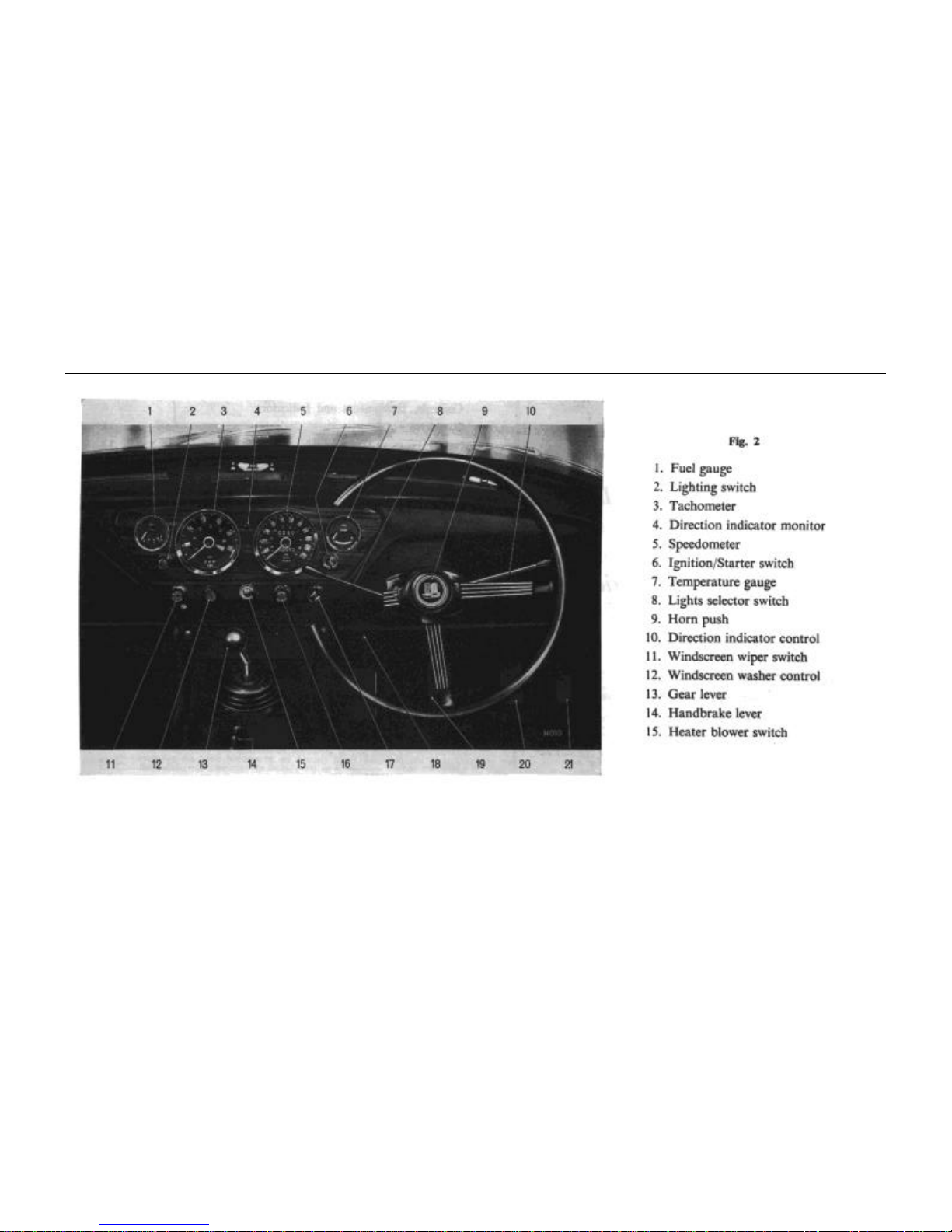
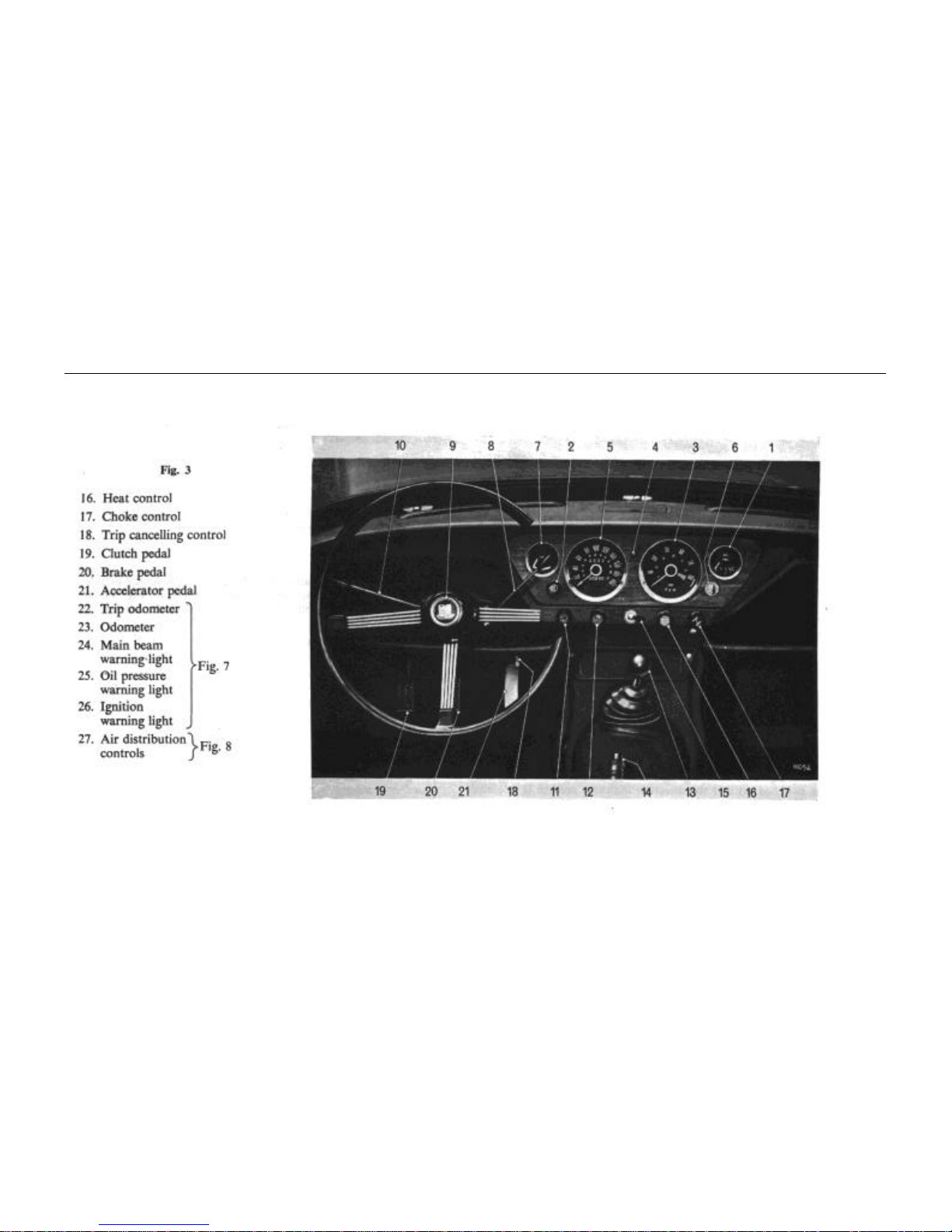
CONTROL, INSTRUMENTS AND IDICATORS
9
The combined ignition and starter switch, Fig. 4, is operated by the
key used for locking the driver's door. The switch has four positions:
4, auxiliary; 1, off (in which position the key may be withdrawn); 2,
ignition; 3, start.
With the key in the "off" position, turn the key clockwise to
switch on the ignition and auxiliary circuits.
To operate the starter motor turn the key clockwise against
spring pressure and when the engine fires release the key which will
return to the ignition position. If the engine fails to start, wait until
the starter motor comes to rest before returning the key to the start
position.
Turning the key anti-clockwise to the auxiliary position permits
the use of a radio when the vehicle is stationary and the ignition is
switched off.
Water Temperature Gauge (7)
Normal operating temperature is reached when the needle
registers in the central sector of the dial. Should the needle reach the
highest mark, stop the engine immediately, allow it to cool and
check the level of the coolant in the radiator. Refer to page 47
Lights Selector Switch (8)
Move the switch lever to the upper position to operate side
lamps only; move the lever to the central position for high beam,
when the high beam is operating a monitor light contained in the
speedometer unit glows blue; move the lever to the lower position
for dipped headlights. Lifting the selector lever towards the steering
wheel flashes the headlight main beams.
Horn Push (9)
Press to operate.
Direction Indicator Control (10)
Move the control lever counter-clockwise to operate the left-
hand flashing indicators and clockwise to operate the right-hand
indicators.
Windscreen Wiper Switch (11)
Pull the switch knob to operate the wipers, and push to switch
them off, when the wipers will automatically return to the parked
position at the base of the windscreen. The wipers operate only
when the ignition is switched on.
Windscreen Washer (12)
The windscreen washer control should be used in conjunction
with the windscreen wiper. Operate by pushing the control to spray
clean fluid onto the screen as the wiper blades disperse the mud. If
the washer has remained unused for some time, depress the control a
few times to charge the system.
Gear Lever (13)
Moving the gear lever from neutral, the gear positions are obtained
as follows: