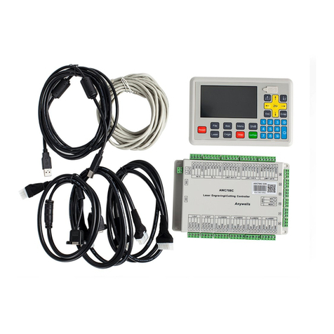
Trocen AWC7824 User manual

AWC7824 motion controller
User manual
Laser motion controller series
RV1.3
2022.03.3
www.sztrocen.com/www.awc608.com
©2016 Trocen All Rights Reserved

AWC7824 motion controller user manual
WWW.SZTROCEN.COM
1
Copyright statement
Shenzhen Trocen Automation Technology Co.Ltd(hereinafter referred to as
Trocen)reserves the right to modify the products and product specifications in this
manual without prior notice.
Trocen shall not be liable for any direct, indirect, special, incidental or
consequential loss or liability arising out of the improper use of this manual or this
product .
Trocen owns the patent right, copyright and other intellectual property rights of
this product and its software. Without authorization, it shall not directly or indirectly
reproduce,manufacture,process or use the product and relevant parts thereof.
Machines in motion are dangerous.
It is the responsibility of the user to design effective error handling and
security protection mechanisms during the use of the machine.
Trocen shall have no obligation orres ponsibility for any incidental or
consequential damages caused thereby.
Contact us
Shenzhen Trocen Automation Technology Co.LTD
Address :1st Floor, Building4, Zhiheng Strategic Industrial Park, Nantou Pass,
Nanshan District, Shenzhen city, Guangdong Province, China.
Thephonenumber : 0755-27958262
Fax: 0755-27447913-608
Email: [email protected]
Url: www.sztrocen.com/www. awc608.com

AWC7824 motion controller user manual
WWW.SZTROCEN.COM
2
Document Version
The version
The revision date
V1.1
2020/07/20
V1.2
2020/08/26
V1.3
2020/08/27
Preface
Thank you for choosing Trocen motion controller! In return for customers, we
will be first-class quality motion controller, perfect after-sales service, efficient
technical support, to help you complete the production of equipment.
More information about Trocen products
The company's website is www.sztrocen.com/www.awc608.com. You can find
out more about our company and products on our website, including: company
profile, product introduction, technical support and latest releases, etc.
You can also call 0755-27958262 for more information about the company and
its products.
Technical support and after-sales service
You can obtain our technical support and after-sales service through the
following ways:
Email: [email protected]
The phone number: 0755-27958262
Sent a letter to: 1stFloor, Building4, Zhiheng Strategic Industrial Park, Nantou
Pass, Nanshan District, Shenzhen city, Guangdong Province, China.
Shenzhen Trocen Automation Technology Co. Ltd.
Zip code: 518100

AWC7824 motion controller user manual
WWW.SZTROCEN.COM
3
Use
By reading this instruction, the user can understand the basic
operation of the AWC7824 control card.
Using the object
This manual is applicable to engineers who have a certain
understanding of mechanical automation operation such as laser
machines.
The main content
The basic operation and use of AWC7813 panel are introduced in
detail. This manual is based on version 1.20.8.12. There are subtle
differences between the versions.
The certification statement
CE certification statement
This product has passed the EU CE (Communate Europpene) safety certification,
has passed the corresponding conformity assessment procedure and the
manufacturer's conformity declaration, and complies with the relevant EU directives.
ROHS certification statement
The product has been certified safe by European Union legislation, the Directive
on Restriction of Certain Hazardous Substances in Electronic And electrical
Equipment, which conforms to the relevant European Union environmental
regulations.

AWC7824 motion controller user manual
WWW.SZTROCEN.COM
4
FCC certification statement
The product has been certified by the Federal Communications Commission
for safety and complies with U.S. electronic product safety regulations.
The relevant documents
《LaserCAD instructions》

AWC7824 motion controller user manual
WWW.SZTROCEN.COM
5
Catalogue
1. Product Description ............................................................................................. 10
1.1 Features ....................................................................................................... 10
1.2 AWC78XX Series Comparison. .................................................................. 11
1.3 Term/abbreviation ....................................................................................... 12
1.4 AWC7824 accessories composition .........................................................13
1.4.1 AWC7824 all accessories and connection diagram ............................ 13
1.4.2 List of accessories. .............................................................................. 14
1.5 Appearance and size of panel. .......................................................................15
1.6 Appearance and size of wiring board. ........................................................... 15
2. Hardware interface introduction ............................................................................. 18
2.1 Control system electrical wiring diagram ...................................................... 18
2.2 Wiring board unit port description and wiring diagram ................................18
2.2.1 Power port. ......................................................................................... 18
2.2.2 Universal input port ............................................................................19
2.2.3 Universal output port ......................................................................... 20
2.2.4 Laser power control port .................................................................... 21
2.2.5 Motor driver control port ................................................................... 22
2.2.6 Limit signal input port. ........................................................................23
2.3 Mainboard interface description ...................................................................26
2.3.1 U Disk interface ................................................................................26
2.3.2 USB interface. .................................................................................. 27
2.3.3 Ethernet interface ...............................................................................29
2.3.4 Panel and terminal board interface .................................................... 29
3. Human Machine Interface Introduction .................................................................. 31
3.1 Main Interface Preview ..................................................................................32
3.2 Function key area ...........................................................................................34
3.2.1 Reset ................................................................................................... 34
3.2.2 File .......................................................................................................34
3.2.3 Menu ...................................................................................................35
3.2.4 More. .................................................................................................. 36
3.2.5 Laser ....................................................................................................36
3.2.6 Box. ..................................................................................................... 37
3.2.7 Origin .................................................................................................. 37
3.2.8 Stop ................................................................................................... 38
3.2.9 Start. ....................................................................................................38
3.2.10 Pause .................................................................................................39
3.2.11 Interface switching ............................................................................40
3.3 Direction key area ..........................................................................................40
3.3.1 X, Y axis movement keys. .................................................................40

AWC7824 motion controller user manual
WWW.SZTROCEN.COM
6
3.3.2 Fast and slow movement switch key.................................................. 41
3.3.3 Z axis Movement Button ..................................................................42
3.4 Processing time display area ......................................................................... 43
3.5 Status display area ......................................................................................... 44
3.5.1 Lockscreen, unlockscreen ................................................................... 44
3.6 Coordinate display area ................................................................................. 45
3.6.1 The coordinate system with the machine zero in the upper left corner
..................................................................................................................... 45
3.6.2 The coordinate system with the machine zero in the upper right
corner ...........................................................................................................46
3.6.3 The coordinate system with the machine zero in the lower left corner
..................................................................................................................... 46
3.6.4 The coordinate system with the machine zero in the lower right
corner ...........................................................................................................47
3.7 Current processing file name display area .................................................... 47
3.7.1 The properties of the processing file ..................................................47
3.7.2 Layer parameters of processing files .................................................. 49
3.8 Count display area. ........................................................................................ 51
3.9 Speed display area ......................................................................................... 53
3.9.1 Quickly modify the key move speed instand by mode .......................53
3.9.2 Modify the speed of the file being processed .................................... 54
3.10 Power display area. ......................................................................................55
3.10.1 Modify Laser power ..........................................................................55
3.10.2 Modify the power of the file being processed ................................. 57
3.11 File operations. ............................................................................................ 58
3.12 U disk transfer files and mainboard upgrade. .......................................... 60
3.12.1 Use U disk to transfer files to mainboard ......................................... 60
3.12.2 Upgrade the mainboard ................................................................... 61
3.13 Origin Manage .......................................................................................... 62
3.13.1 Set origin coordinates ....................................................................... 63
3.13.2 Move the laser head to the set origin .............................................. 63
3.14 Motion Parameters Settings ........................................................................ 64
3.14.1 Description of each parameter .........................................................65
3.14.1.1 Space Speed ...........................................................................66
3.14.1.2 Cut Jerk .................................................................................. 66
3.14.1.3 Space Jerk. ............................................................................. 66
3.14.1.4 Min Acc. ................................................................................. 67
3.14.1.5 Engrave Acc ............................................................................67
3.14.1.6 Start Speed .............................................................................68
3.14.1.7 Speed Factor .......................................................................... 68
3.14.2 Example analysis ............................................................................... 69

AWC7824 motion controller user manual
WWW.SZTROCEN.COM
7
3.14.2.1 Wavy lines appear when cutting arcs .................................... 69
3.14.2.2Wavy lines appear at the beginning and corners of the cutting
............................................................................................................. 69
3.15 Common Parameters Settings ..................................................................... 70
3.15.1 Work Mode ....................................................................................... 70
3.15.1.1 Go Origin After Reset. ............................................................71
3.15.1.2 Origin Mode. ..........................................................................71
3.15.1.3 Go Back Position .................................................................... 72
3.15.1.4 Count Mode ........................................................................... 72
3.15.2 Common Parameters........................................................................ 74
3.15.2.1 AutoFocus Distance(mm) ................................................... 78
3.15.2.2 KeyMove’Speed(mm/s) ...................................................... 78
3.15.2.3 RunBox’Speed(mm/s) ......................................................... 79
3.15.2.4 CutBox’Speed(mm/s) ..........................................................79
3.15.2.5 Blow Open Delay(s) ................................................................79
3.15.2.6 Blow Close Delay(s). ...............................................................79
3.15.3 Axis Speed Parameters..................................................................... 80
3.15.3.1 Z Work Speed(mm/s). ......................................................... 81
3.15.3.2 X Y Home Speed(mm/s) ......................................................81
3.15.3.3 Z Home Speed(mm/s.......................................................... 81
3.15.4 Rotate Engraving & Cutting ...............................................................82
3.16 Manufacturer Parameters Settings ..............................................................86
3.16.1 Axis Parameters (take X axis as an example) .................................... 86
3.16.1.1 Distance Per Pulse(um) ..........................................................88
3.16.1.2 Valid Pulse Edge ..................................................................... 91
3.16.1.3 Datum Direction .....................................................................91
3.16.1.4 Key Direction ..........................................................................92
3.16.1.5 Limit-Switch Valid Level ......................................................... 92
3.16.1.6 Range(mm). ........................................................................... 93
3.16.1.7 Start Speed .............................................................................93
3.16.1.8 Max Acc ..................................................................................93
3.16.1.9 Max Speed ............................................................................. 93
3.16.1.10 Zero Offset ........................................................................... 94
3.16.2 Laser Parameters. ............................................................................. 94
3.16.2.1 Laser Mode. ........................................................................... 95
3.16.2.2 TTL Valid Level ........................................................................96
3.16.2.3 PWM Frequency(hz) .............................................................. 96
3.16.2.4 Max Power(%) ........................................................................96
3.16.2.5 RF Min Power(%) ................................................................... 97
3.16.2.6 Laser 1 Water Protect. ........................................................... 97
3.16.3 IO Parameters................................................................................ 97

AWC7824 motion controller user manual
WWW.SZTROCEN.COM
8
3.16.3.1 Foot Switch ............................................................................ 98
3.16.3.2 Open Protection .....................................................................99
3.16.3.3 Input Valid Level ............................................................... 101
3.16.4 Auto Reset Settings. ........................................................................100
3.16.5 HardLimit Settings ...........................................................................102
3.16.6 Function Configuration. .................................................................. 109
3.16.6.1 Z-Axis For Autofocus ......................................................... 111
3.16.6.2 Y&Z Double-Driver Control.. ............................................. 114
3.17 Network Settings ....................................................................................... 116
3.18 Language ....................................................................................................118
3.19 System Version ...........................................................................................120
3.20 Input Test. .................................................................................................. 120
3.21 Output Test. ............................................................................................... 121
3.22 Cut Box. ......................................................................................................122
3.23 Axis Reset. ..................................................................................................124
3.24 Key Moving ................................................................................................ 125
3.25 Z AutoFocus, X&Y to Origin and Continue to Previous Work ................126
3.25.1 Run Z AutoFocus function ...............................................................127
3.25.2 Set X&Y to Origin ............................................................................ 129
3.25.3 Continue to Previous Work .............................................................129
4. Frequently Asked Questions .................................................................................. 132
4.1 What kind of U disk can the system read? .................................................. 132
4.2 Why does the prompt "Engrave beyond border limit!"appear................... 133
4.3 Why doe sthe prompt "Beyond border limit ! Continue?"appear .............. 134
4.4 Why does the prompt "Beyond border limit!"appear .................................138
4.5 Why does the prompt"Trigger limit!"appear .............................................. 138
4.6 Why does the prompt "Nofile!"appear ....................................................... 139
4.7 Why does the prompt To select the file!"appear.........................................140
4.8 Why does the prompt"Continue to work?"appear......................................141
4.9Why does the button movement speeds low down after turning on the
rotary engraving function? ................................................................................ 142
4.10 Why does the prompt"water protect!"appear ..........................................142
4.11 Why does the prompt"opened protected!"appear ...................................143
5. Operation process description. ..............................................................................145
5.1 Machine installation and debugging process. ............................................. 145
5.2 Basic steps of using the laser machine to cut graphs .................................. 146

AWC7824 motion controller user manual
WWW.SZTROCEN.COM
9
1.Product description
Features
AWC78XX Series comparison
Terms/abbreviations
AWC7824 accessories composition
Appearance and size of panel
Appearance and size of wiring
board
1.产品介绍

AWC7824 motion controller user manual
WWW.SZTROCEN.COM
10
1. Product Description
1.1 Features
AWC7824 is a general-purpose motion controller used in laser cutting, laser
engraving and other fields, suitable for all kinds of small and medium power laser
cutting and engraving equipment .AWC7824 motion controller works with LaserCAD
software
AWC7824 motion controller has the following features::
5-inch TFT LCD touch screen ,intuitive and simple operation interface
Two road laser control
Four-roads motion axis control (X axis, Y axis, Z axis ,U axis )
Using high-speed DSP main control chip, fast calculation
speed,advanced motion algorithm
All optocouplers isolate external electromagnetic interference, and the
system works stably and reliably
Support U disk, network and USB communication methods
Support Z-axis autofocus, Y-axis dual drive function
Support full blowing, work blowing, layer blowing
Support double-head mutual movement, support over size cutting
Support Y-axis drum cutting, Y@U-axis synchronous feeding, Y-axis double
limit
Support U-axis automatic feeding or optional U-axis as rotation axis
Support dispensing function
Support system startup delay, choose whether to turn off the system
sound

AWC7824 motion controller user manual
WWW.SZTROCEN.COM
11
1.2 AWC78XX Series Comparison
AWC78XX Series comparison
AWC7813
AWC7824
AWC7846
Hardware
screen
5-inch touch
screen
5-inch touch
screen
5-inch touch
screen
Universal output port
8roads
8roads
8roads
Universal input port
6roads
6roads
6roads
Control axis
3axes
4axes
6axes
Control laser
1road
2road
4roads
Memory size
128M
128M
128M
Data transmission method
Network communication,USB communication,U
disk
Support laser
Various DC lasers,RF lasers,CO2 lasers
Function
Input test interface
Yes
Yes
Yes
Output test interface
Yes
Yes
Yes
Button speed and slow
movement function
Yes
Yes
Yes
Single axis quick reset operation
Yes
Yes
Yes
Quickly return to the positioning
point
Yes
Yes
Yes
Modify power and speed online
Yes
Yes
Yes
Modify layer parameters offline
Yes
Yes
Yes
Modify file processing attributes
offline
Yes
Yes
Yes
Modify factory parameters
Yes
Yes
Yes
Counting function
Yes
Yes
Yes
Graphic preview of processing
files
Yes
Yes
Yes
Processing file completion
progress display
Yes
Yes
Yes
Real-time follow-up display of
cutting file graphics
Yes
Yes
Yes
Multi-head shift number
No
2roads
4roads

AWC7824 motion controller user manual
WWW.SZTROCEN.COM
12
Dispensing function
No
Yes
Yes
Z-axis auto focus function
Yes
Yes
Yes
Y-axis dual drive function
Yes
Yes
Yes
Continue cutting function
Yes
Yes
Yes
Main board online upgrade
Yes
Yes
Yes
Automatic feeding,Y/U
synchronous feeding
No
Yes
Yes
Over-format cutting
No
Yes
Yes
Drum cutting function
No
Yes
Yes
Blow by layer
Yes
Yes
Yes
Dispensing function
No
Yes
Yes
Y-axis double limit
No
Yes
Yes
System startup delay
No
Yes
Yes
Turn off system sound
yes
Yes
Yes
Set the U axis as the rotation
axis
No
Yes
Yes
1.3 Term/abbreviation
Table 1-3 Explanation of terms and abbreviations
Term/abbreviation
explain
PC software
Laser CAD software is dedicated software for Trocen laser
motion controller.
TFT LCD panel
LCD panel
Control panel
Panel (Mainboard)
Refers to the 5-inch TFT color LCD touch control panel.The
panel is used for specific display and control operations
and is an important part of the system.
Wiring board(base
plate)
The wiring board is a control board that controlling
integrated signal input and output and connecting motor
driver.
System hardware
The physical objects visible to the

AWC7824 motion controller user manual
WWW.SZTROCEN.COM
13
system,including:panel,wiring board,wires,etc.
1.4 AWC7824 accessories composition
After receiving the product, please confirm whether the product and accessories are
complete. If there is any missing, please contact Shenzhen Trocen Automation
Technology Co.Ltd. after-sales customer service.
1.4.1 AWC7824 all accessories and connection diagram

AWC7824 motion controller user manual
WWW.SZTROCEN.COM
14
1.4.2 List of accessories
Table 1-4-2 Product list
Name
Appearance
Description
Panel
(1piece)
AWC7824 Control panel
Wiring board
(1piece)
AWC7824 Wiring board (base plate)
USB cable
(1piece/3m)
Used by the computer to load files to
the panel
Cable
(1piece/5m)
Used by the computer to load files to
the panel
CN Cable
(1piece/1.6m)
Connect the CN1 port of the panel and
wiring board
USB extension
cable
(1piece/0.5m)

AWC7824 motion controller user manual
WWW.SZTROCEN.COM
15
Network
extension
cord(1piece/0.5m)
Screw (2pcs)
Used to fix the panel
1.5 Appearance and size of panel
Figure 1-5-1 Panel appearance display
Figure 1-5-2 Panel size diagram
1.6 Appearance and size of wiring board
Figure 1-6-1 Appearance display of wiring board
5-inch touch screen
U Disk Jack

AWC7824 motion controller user manual
WWW.SZTROCEN.COM
16
209mm
Figure 1-6-2 Wiring board size diagram
195mm
2.硬件接口介绍

AWC7824 motion controller user manual
WWW.SZTROCEN.COM
17
2.Hardware interface introduction
Control system electrical wiring diagram
Wiring board unit port description
and wiring diagram
Mainboard interface description

AWC7824 motion controller user manual
WWW.SZTROCEN.COM
18
2. Hardware interface introduction
2.1 Control system electrical wiring diagram
2.2 Control system electrical wiring diagram
2.2.1 Power port
It is used to supply power to the wiring board and the panel. When connecting,
be careful to the positive and negative poles. Generally need DC24V 3A switching
power supply.

AWC7824 motion controller user manual
WWW.SZTROCEN.COM
19
Terminal number
Terminal name
Description
1
24V
24V power supply positive
2
GND
24V power ground
2.2.2 Universal input port
The wiring board provides two sets of input signal terminals for the collection of
input signals. The default value of all input valid signals is 0V,and the default value of
waiting signal is 24V when not working.
Terminal group
Silk screen
Description
6P terminals
24V
24V power supply positive output
IN4
Reserved input signal
IN3
Reserved input signal
IN2
Foot switch signal
IN1
Open protection signal
GND
Power ground-output signal
4P terminals
24V
24V power supply positive output
IN6
Reserved input signal
IN5
Reserved input signal
External earth-output signal
The signal input electrical wiring diagram is as follows:
IN1:door open
IN2:foot pedal
close on contact
Table of contents
Other Trocen Controllers manuals
Popular Controllers manuals by other brands
MidNite Solar
MidNite Solar Classic 250 owner's manual
National Instruments
National Instruments PXI-8186 installation guide

TANDBERG
TANDBERG Border Controller user guide
Sony
Sony JumboTron operating instructions
Meaco
Meaco LAE quick start guide
Endress+Hauser
Endress+Hauser Liquiline CM442 Brief operating instructions
