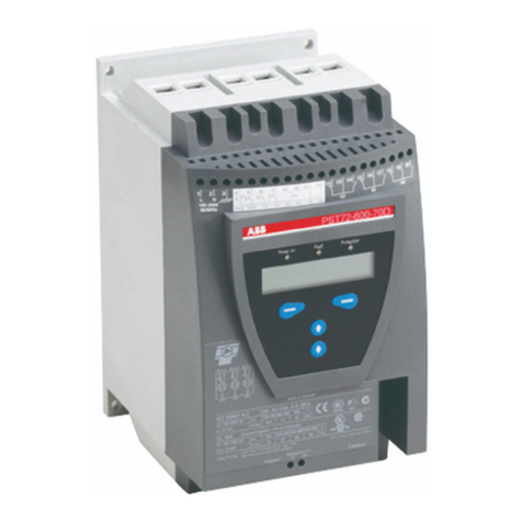
ABB PSE User manual

1SFC132374M0201 1
Cyber Security Legal Disclaimer
This product is designed to be connected to and to communicate information and data via a network interface. It
is your sole responsibility to provide and continuously ensure a secure connection between the product and your
network or any other network (as the case may be). You shall establish and maintain any appropriate measures
(such as but not limited to the installation of firewalls, application of authentication measures, encryption of data,
installation of anti-virus programs, etc.) to protect the product, the network, its system and the interface against
any kind of security breaches, unauthorized access, interference, intrusion, leakage and/or theft of data or
information. ABB Ltd and its affiliates are not liable for damages and/or losses related to such security breaches,
any unauthorized access, interference, intrusion, leakage and/or theft of data or information.
Risk Mitigation and Secure Deployment
The idea is to create defence-in-depth protection for each network by allocating firewall solutions to the front of
internal trusted networks of each network by manage firewalls, their configurations and access rules. The
softstarter must be positioned in a trusted network, strictly limited and in a hosted portion of a network or control
system. Configure firewalls according to the principle of denying everything that is not needed nor used. For
secure remote access, use a VPN connection with an encryption layer to create a secure channel over an insecure
network. For more information regarding cyber security and risk mitigation, download the document Cyber
security for ABB drives from the ABB library.
Note: The device uses the default Modbus TCP port 502 (0x01F6). This port must be open in the firewall for
both incoming and outgoing traffic to allow Modbus-TCP compatible devices to communicate.

1SFC132374M0201 2
Contents
1Overview........................................................................................................................................................ 3
2Technical Description..................................................................................................................................... 4
2.1 Modbus TCP.......................................................................................................................................... 4
2.2 MTQ22-FBP.......................................................................................................................................... 5
2.3 Connection Setup................................................................................................................................... 6
3Software Configuration .................................................................................................................................. 7
3.1 PSE Softstarter....................................................................................................................................... 7
3.2 MTQ22-FBP........................................................................................................................................ 10
4Modbus TCP Register Map.......................................................................................................................... 14
4.1 Digital Input Telegram ........................................................................................................................ 14
4.2 Digital Output Telegram...................................................................................................................... 16
4.3 Analog Input Telegram........................................................................................................................ 17
4.4 Parameters ........................................................................................................................................... 17
4.5 Diagnostics .......................................................................................................................................... 18
4.5.1 MTQ22-FBP ................................................................................................................................... 18
4.5.2 PSE Softstarter ................................................................................................................................ 18
5MTQ22-FBP LED Diagnostics in Case of Error.......................................................................................... 20
6Basic TCP Modbus Diagnostic Information ................................................................................................ 21

1SFC132374M0201 3
1 Overview
This document aims to describe the installation and configuration process of the MTQ22-FBP Modbus TCP
adapter module. Modbus is a master-slave protocol and only one device can transmit on the line at any time. The
master (which in most cases is a PLC) manages the exchanges and only it can take the initiative. It interrogates
each of the slaves in succession and no slave can send a message unless it is invited to do so. The master repeats
the question when there is an incorrect exchange, and declares the interrogated slave absent if no response is
received within a given time period. If a slave does not understand a message, it sends an exception response to
the master who may or may not repeat the request.
The adapter will be used to enable Modbus TCP communication between an ABB PSE softstarter and a Modbus
master over an IP network. The TCP Modbus communication protocol differs from the other Modbus versions
through the use of TCP/IP communication as a wrapper for the Modbus data. Modbus RTU messages are sent
over an IP network. The use of IP datagrams removes the need for slave addresses since all slaves use a unique
IP address to enable IP communication. However, The MTQ22-FBP still uses Modbus RTU to communicate
with the PSE which require the slave ID to match between the MTQ22-FBP and the PSE, as explained in section
3.2.
The document starts with technical information regarding the required devices and a description of how to
connect them to enable Modbus TCP communication. The third chapter explains how to configure the PSE and
MTQ22-FBP software, Fieldbus Control, Slave address, IP address and other important parameters are
configured with detailed instructions. The fourth chapter presents the MTQ22-FBP data registers, used to read or
write data to the connected PSE devices. In case of any TCP Modbus connection problems, chapter 5 explains
the meaning of the MTQ22-FBP diagnostic LED indicators. This manual is written specifically for Modbus TCP
and will not cover other fieldbus protocols or other devices then ABB Softstarters type PSE18…PSE370. For
more detailed information regarding warranty, service, type designation and other product specific information
for the associated devices, see respective manual.
Requirements
To connect the PSE Softstarter to a fieldbus system, the following accessories are required:
•ABB FieldBusPlug Accessory (FBPA)
•ABB MTQ22-FBP (Modbus TCP)
•Cable for bus connection (CDP19-FBP .100)
•Micro USB cable
•ABB PSE softstarter
•Software for MTQ22-FBP set-up (ABB Config Tool)
•PLC or another Modbus TCP master
1SFC132374M0201 4
2 Technical Description
The following list highlights the core features and functionalities provided by the MTQ22-FBP and Modbus TCP
protocol.
Highlighted Features
The MTQ22-FBP Ethernet adapter module provides Ethernet connectivity for the ABB PSE softstarter
Fieldbus plug (FBP) device.
Up to four FBP devices can be connected to one MTQ22-FBP. This allows a very cost-efficient
connection of FBP devices to Ethernet.
Through the MTQ22-FBP Ethernet Adapter module it is possible to:
oGive control commands to the device (Start, Stop, Set Auto Mode, etc.)
oRead status information and actual values from the device
oRead maintenance counters
oReset a trip
A built in two-port switch allows the flexible usage in bus, star or ring network topologies.
Up to four masters can concurrently access the connected devices.
Access via Modbus TCP can be restricted to a limited set of IP addresses.
The Media Redundancy Protocol (MRP) is implemented (client). MRP is standardized in IEC/EN
62439-2 and offers cable redundancy in case of a single failure.
2.1 Modbus TCP
Modbus TCP is a variant of the Modbus family of simple, vendor neutral communication protocols intended for
supervision and control of automation equipment. Specifically, it covers the use of Modbus messaging over TCP
connections on an IP network.
The implementation of the Modbus TCP server in the MTQ22-FBP module is done according to:
Modbus Application Protocol Specification v1.1b
Modbus Messaging on TCP/IP Implementation Guide v1.0b
The supported Modbus commands can be found in chapter 4. Further information on the Modbus TCP protocol
is available at www.modbus.org.

1SFC132374M0201 5
2.2 MTQ22-FBP
A device layout of the MTQ22-FBP can be seen in Figure 1. Connectors X1 ... X4 are used to connect up to four
FBP devices to the MTQ22-FBP. On the left side of the port connectors LEDs show the current communication
status. See chapter 5 for detailed information regarding status LEDs.
Figure 1: Top view of the MTQ22-FBP. Four PSE devices can be connected to the MTQ22 via the ports X1 to X4. The
standard Micro USB connector X5 allows to configure the device.
The Micro USB connector X5 allows device configuration using a PC, see chapter MTQ22-FBP. Two RJ45
sockets E1 and E2 offer Ethernet connectivity. The communication status of each interface is shown by two
LEDs. The MTQ22-FBP must be supplied with 24VDC via X6.
Mounting and Dismounting
You can mount and dismount the MTQ22-FBP onto a 35 mm standard mounting rail, without tools.
Arrange the communication cables as far away from the motor cables as possible. Avoid parallel runs. Use
bushings at cable entries. The network cable is connected to the RJ45 connectors on the MTQ22-FBP module.
Standard CAT5 UTP, FTP or STP cables can be used. The shield of the RJ45 cable is connected to the shield of
connector X6.

1SFC132374M0201 6
2.3 Connection Setup
In order for Modbus to function properly the PSE must be connected point-to-point with a Fieldbus Plug
Accessory (PS-FBPA) as seen in Figure 2. Further the PS-FBPA must be connected to one of the ports named
X1 to X4 on the MTQ22-FBP. The Modbus master is in turn connected to one of the Ethernet connections E1 or
E2.
Figure 2: Device connections required to enable a Modbus TCP connection between the PSE and a Modbus master.
The cable connecting the PS-FBPA and the MTQ22-FBP, a CDP19-FBP .100 cable must be purchased
separately. A spring terminal block connector must also be installed on the separate cable and connected
according to Figure 3.
Figure 3: MTQ22-FBP port connection specification.

1SFC132374M0201 7
3 Software Configuration
This chapter describes how to configure the MTQ22-FBP and the PSE to enable Modbus communication.
3.1 PSE Softstarter
The following list of instructions explains how to configure the fieldbus parameters on the PSE softstarter.
1. Fieldbus Control
This parameter is used for configuration of the fieldbus communication. Connecting the PSE Softstarter to the
Fieldbus plug automatically enables fieldbus communication. To enable control of the softstarter using fieldbus,
this parameter must be set to On. If Fieldbus Control is set to OFF, fieldbus can only be used for monitoring
softstarter data.
If this parameter is set to On, the softstarter might trip on fieldbus
fault if no fieldbus communication is available. If the intention is
to run without fieldbus control, this parameter should be set to
OFF.
2. Fieldbus Address
The parameter Fieldbus Address allows setting of address for the fieldbus communication. The setting range for
the fieldbus address is 0...255. If the address is set to 255, the address stored in internal memory of the fieldbus
plug will be used.
It is possible to read and set this parameter via the keypad when Fieldbus Control is set to On or OFF.
Changing this parameter will automatically reset the fieldbus
interface and the new address will be active. If MTQ22-FBP was
communicating with the old address, the MTQ22-FBP needs to be
re-configured and the PSE restarted.
Default value
Setting range
Description
255
0…255
Fieldbus Address

1SFC132374M0201 8
3. Fieldbus Type
The fieldbus type parameter must be set to FbP (fieldbus plug) when using the MTQ22-FBP. FbP is the default
value of the parameter. The PSE has a built-in version of Modbus which is activated by setting the parameter to
Int (Internal).
When FbP is selected –configured to use external fieldbus plug,
such as the MTQ22-FBP.
When Init is selected –PSE will use the internal Modbus
implementation to communicate with external devices.
Default value
Setting range
Description
FbP
FbP/Int
FbP enables the use of external
fieldbus plugs. The Int parameter
should be set when using the
internal Modbus interface
4. Download Parameter
This parameter allows for blocking parameter download from the fieldbus. Note that download of parameters
works differently for different fieldbus protocols. See documentation for the protocol used.
It is possible to read and set this parameter via the keypad when
Fieldbus Control is set to On or OFF.
Default value
Setting range
Description
dPon
dPo/dPof
Enable/disable parameter
download

1SFC132374M0201 9
5. Fieldbus Operation When Fault
This parameter is accessible only if Fieldbus Control is previously set to On.
In case of fieldbus malfunction, for instance due to power loss or a broken cable, this parameter allows for
different (operations in case of a fault) reactions to the fault.
Setting Fieldbus fault reaction to trIP will make the softstarter trip on a fieldbus fault. Selecting trIP makes reset
of the fault necessary, in case of a tripping event.
When LocC is selected, the control of the softstarter will
automatically switch from fieldbus control to local control. The
switch to local control will make hard-wire control possible. When
the Fieldbus starts working again the control is automatically
switched back to the Fieldbus. There is a 10 second delay before it
is possible to controlling the motor.
Default value
Setting range
Description
LooC
Looc/trlP
Trip on fieldbus fault or
automatically move to local
control on fieldbus fault
6. Type of Operation for Reset of Fieldbus Fault
Select what operation shall be asserted if a fieldbus communication fault occurs. Manual or automatic options
are available. HAnd is the default value for reset of Fieldbus Fault:
• If HAnd is selected - The motor will stop and manual
reset is required.
• If Auto is selected - The motor will stop and automatic
reset is performed.
This parameter is accessible only if trIP is previously
selected for the parameter fieldbus Operation When
Fault.
Default value
Setting range
Description
HAnd
HAnd/Auto
Hand require manual reset of
fieldbus fault while Auto will
perform the reset automatically.

1SFC132374M0201 10
3.2 MTQ22-FBP
An easy to use PC configuration tool is provided to adjust the parameters of the MTQ22-FBP. The PC can be
connected to the MTQ22-FBP with a standard Micro USB-cable. The ABB Configuration Tool can be
downloaded by clicking the following link or searching for 1SAJ260900R0001 at the ABB Download Center.
Figure 4: Connecting the MTQ22-FBP to a service Laptop. The MTQ22-FBP must be supplied with 24V DC before the
configuration can take place (1). For the connection a Micro USB cable (2) is used. On the PC the MTQ22-FBP
configuration software must be installed (3).
If the MTQ22-FBP is connected for the first time the required USB driver has to be installed. The Microsoft
USB driver is not part of the software package because of license reasons. It is pre-installed on Windows 7 and
10, for XP it must be downloaded separately from Microsoft. Follow the setup instructions of Windows to install
the new software. After startup of the application the screen is split into three areas - left, middle and right. In the
left area you can add as many MTQs as you have in your project. In the middle area the configuration parameters
per MTQ22-FBP are displayed. You can change them offline or online. The right area shows a short help text.
Make sure to start the Configuration Tool as administrator and to connect the USB cable between the PC and
MTQ22-FBP before the program is started.

1SFC132374M0201 11
Set required MTQ22-FBP parameters
The following steps describes how to set the required parameters on the MTQ22-FBP.
1. After the application is started (as administrator) select the MTQ22-FBP that you want to configure in
the Config Tool.
2. From the Select port drop down menu select the COM port associated to the MTQ22-FBP and click
connect. The number of the COM port varies, make sure to select the one connected to the MTQ22-
FBP.

1SFC132374M0201 12
3. Use the following table to set the required parameters. Remember to adjust the parameters to suite your
specific network settings.
Parameter name
Default settings
DHCP / BOOTP
Manual
IP Address
192.168.171.254
Subnet Mask
255.255.255.0
Standard Gateway
192.168.171.1
Number of Modbus TCP masters under supervision
1
Allowed number of supervised connections missing
0
Allowed Modbus TCP IP Address for master 1 ... 4
0.0.0.0 ... 255.255.255.255 for master 1
0.0.0.0 ... 0.0.0.0 for master 2-4
Timeout for master 1 ... 4
10s
Device port 1 ... 4 used
PSE
Device address for device 1 ... 4
1,2,3,4
4. Select the connected FBP device and chose PSE in the drop-down menu called Expected device. For the
ports without a connected device chose Port not used.

1SFC132374M0201 13
5. When all Expected device parameters for FBP Device 1 to 4 are adjusted click the Write to MTQ22-
FBP button to upload the configuration to the device.
6. Select the FBP Devices in the Config Tool and set the expected Device address to match the Device
address read by the MTQ22-FBP. When the two Device addresses match for all connected PSEs click
the Write to MTQ22-FBP button again. Note that, when the slave ID is updated in the PSE a reboot will
be required on the PSE for the Config Tool to the detect the new value.
7. The MTQ22-FBP is now configured and should be able to communicate with the PSE.

1SFC132374M0201 14
4 Modbus TCP Register Map
The following chapter shows how to generally access data of the FBP-devices connected to port one to port four
of the MTQ22-FBP.
Modbus TCP counts registers beginning with one. But on the bus registers start counting
from zero. The addresses in this manual describe the addresses that are transmitted on the
network. Depending on your client application it might be necessary to increment all
addresses by one.
The I/O-data as well as diagnostic and configuration data of the connected PSE devices can be accessed applying
the supported Modbus function codes. The supported functions can be found in respective sub section.
4.1 Digital Input Telegram
To read the digital input telegram, use Modbus function code 1 Read Coil Status or 2 Read
Discrete Inputs.
Address for data access to device connected to port
Data
Description
1
2
3
4
1000h
1010h
1020h
1030h
Reserved
1001h
1011h
1021h
1031h
Stop
0 = Motor running
1 = Motor stopped
1002h
1012h
1022h
1032h
Run
0 = Motor stopped
1 = Motor running
1003h
1013h
1023h
1033h
Reserved
1004h
1014h
1024h
1034h
Reserved
1005h
1015h
1025h
1035h
Auto mode1
0 = Local control
1 = Modbus master
control
1006h
1016h
1026h
1036h
Fault
0 = No active fault
1 = One or more active
faults
1007h
1017h
1027h
1037h
Reserved
1008h
1018h
1028h
1038h
Reserved
1009h
1019h
1029h
1039h
DI_FBP_Trip
0 = No trip on DI_FBP
adaptor
1= Trip on DI_FBP
adaptor
100Ah
101Ah
102Ah
103Ah
DI_FBP_Local
0 = Remote control
1 = Local control
100Bh
101Bh
102Bh
103Bh
DI_Start
Hardwire DI Start input
signal state
0 = DI Start signal
inactive
1 = DI Start signal
active

1SFC132374M0201 15
100Ch
101Ch
102Ch
103Ch
DI_Stop
Hardwire DI Stop input
signal state
0 = DI Stop signal
inactive
1 = DI stop signal active
100Dh
101Dh
102Dh
103Dh
DI_Reset
Hardwire DI Reset input
signal state
0 = DI Reset signal
inactive
1 = DI Reset signal
active
100Eh
101Eh
102Eh
103Eh
TOR
0 = Softstarter is not in
top of ramp
1 = Softstarter is in top
of ramp (bypass closed)
100Fh
101Fh
102Fh
103Fh
Ready to start
0 = No faults are active,
control supply voltage is
stable and motor will
start when start
command is given
1 = Fault is active or
control supply voltage is
not stable and motor will
not start when start
command is given
1) Auto mode reflects the control state of the Softstarter. This is affected by a combination of:
The Auto mode input signal from the Modbus master (protocol address 0105h in the digital output telegram)
The state of the Local/Remote switch on the Fieldbus Plug Accessory.

1SFC132374M0201 16
4.2 Digital Output Telegram
To write the digital output telegram, use Modbus function code 5 Write Single Coil or 15 (0Fh)
Force Multiple Coils. To read the digital output telegram, use Modbus function code 1 Read Coil
Status or 2 Read Input Status.
Address for data access to device connected to port
Data
Description
1
2
3
4
1800h
1810h
1820h
1830h
Reserved
1801h
1811h
1821h
1831h
Stop
Commence a stop when
this coil is set (this coil has
higher priority than the
start coil). The stop coil is
only acknowledged if the
Auto mode coil is set.
1802h
1812h
1822h
1832h
Start
Commence a start when
this coil is set. The start
coil is only acknowledged
if the Auto mode coil is
set.
1803h
1813h
1823h
1833h
Reserved
1804h
1814h
1824h
1834h
Reserved
1805h
1815h
1825h
1835h
Auto mode
This coil must be set for
controlling the motor.
1806h
1816h
1826h
1836h
Fault reset
Reset an active fault or
protection when this coil is
set.
1807h
1817h
1827h
1837h
Reserved
1808h
1818h
1828h
1838h
Reserved
1809h
1819h
1829h
1839h
Reserved
180Ah
181Ah
182Ah
183Ah
Reserved
180Bh
181Bh
182Bh
183Bh
Reserved
180Ch
181Ch
182Ch
183Ch
Clear active
diagnostics
Clear active diagnostics
when this coil is set
180Dh
181Dh
182Dh
183Dh
Reserved

1SFC132374M0201 17
4.3 Analog Input Telegram
All analog input telegram data values are represented as 16-bit values. To read the analog input telegram, use
Modbus function code 3 Read Holding Registers or 4 Read Input Registers.
Address for data access to device connected to port
Data
Representation
1
2
3
4
2000h
2100h
2200h
2300h
Motor current
in % of Ie (0%-
800%)
Value = 1 ⇒1%
2001h
2101h
2201h
2301h
Thermal load in
% of trip
temperature
(0%-100%)
Value = 1 ⇒1%
2002h
2102h
2202h
2302h
Phase current
L1
Value = 1 ⇒1A
2003h
2103h
2203h
2303h
Phase current
L2
Value = 1 ⇒1A
2004h
2104h
2204h
2304h
Phase current
L3
Value = 1 ⇒1A
2005h
2105h
2205h
2305h
Max phase
current
Value = 1 ⇒1A
2006h
2106h
2206h
2306h
Measured
frequency
Value = 1 ⇒1Hz
2007h
2107h
2207h
2307h
Measured
power factor
Value = 100 ⇒1
2008h
2108h
2208h
2308h
Output voltage
in % of line
voltage
Value = 1 ⇒1%
2009h
2109h
2209h
2309h
Counted
number of
starts
Value = 1 ⇒100
200Ah
210Ah
220Ah
230Ah
Run time in
hours
Value = 1 ⇒10h
4.4 Parameters
The MTQ22-FBP does not support reading or writing PSE softstarter parameters such as start ramp time, initial
voltage and torque control.

1SFC132374M0201 18
4.5 Diagnostics
To read the diagnostics data, use Modbus function code 3 Read Holding Registers or 4 Read
Input Registers. The following chapter presents register values associated to diagnostic data for both PSE
and MTQ-FBP devices.
4.5.1 MTQ22-FBP
The status of the connected FBP devices can be read via Modbus TCP on the addresses 0x80 to 0x83 for the
devices connected to port 1 ... port 4.
Address
FBP communication status
80h
Port 1
81h
Port 2
82h
Port 3
83h
Port 4
The communication status is zero (0) in case of no error. A value different from zero indicates an error. The
value itself describes the error reason.
Error Code
Description
Possible Reasons, Corrective Measures
0
OK
-
1
Wait for FBP device.
Communication not yet
established.
Check that the FBP device is powered.
Check the wiring between the FBP device and
the MTQ22-FBP.
2
Unsupported FBP Device. An
unsupported device was
connected to the MTQ22-FBP.
Check that a PSE is connected and not another
device.
3
Communication Fault on Module
Port. Communication to a FBP
device was established but was
lost again.
Check the FBP device.
Check that the FBP device is powered.
Check that the drawer is inserted (in a
withdrawable system)
4
Address mismatch. The
configured device address and the
real PSE device address do not
match.
Fix parameterization
Check that the connected PSE was not
interchanged (e.g. wrong drawer inserted).
5 - 10
General configuration error
Double-check the configuration
Check that no unsupported device was
connected.
Check configuration data sent to the MTQ22-
FBP (if own config was sent)
Other values
Reserved
-
4.5.2 PSE Softstarter
PSE softstarter diagnostics are represented by bits in a 16-unsigned integer register. Use a calculator to translate
the decimal number to one or more bits. If a bit is set that fault is active and could potentially be resetted.
Address for data access to device
connected to port
Bit
Data
Description
1
2
3
4
C00h
C20h
C40h
C60h
0
Reset possible on
active event
Current fault or protection
can be reset
1
Software fault
Internal fault
2
Shunt fault
Current is flowing when it
should not
3
By-pass open
By-pass does not close
4
Softstarter overload
Too high thyristor- or heat
sink temperature
5
Phase loss
No voltage in one or more
phases on the line side

1SFC132374M0201 19
6
Bad network quality
Bad network quality on the
line side
7
Current loss
Current is not flowing when
it should
8
Fieldbus fault
Fieldbus communication
failure
9
Low supply voltage
Too low control supply
voltage
10
High current
Too high current
11
Motor overload
Too high motor temperature
12
Locked rotor protection
Current is higher than
settable value during top of
ramp
13
Underload protection
Current is lower than
settable value during top of
ramp
14
Reserved
15
Reserved
C01h
C21h
C41h
C61h
0..15
Reserved
C02h
C22h
C42h
C62h
0..15
Reserved
C03h
C23h
C43h
C63h
0
Reserved
1
Reserved
2
Reserved
3
Reserved
4
Parameter is read-only
This bit is set if a parameter
write operation failed due to
the parameter being read-
only.
5
Parameter is not
settable
This bit is set if a parameter
write operation failed due to
the parameter not being
settable (such as during a
soft start or soft stop).
6
Parameter value is out
of range
This bit is set if a parameter
write parameter operation
failed due to the set value
being out of range.
7
Extended diagnostic
available
If set, fault code provides
extended diagnostics.
8..15
Fault code
This can be additional info
for a fault such as in which
phase the fault occurred or
the parameter number of the
latest read/write parameter
operation failure.
The diagnostic data is composed of a bit map of all potential faults and protections, as well as a flag, which
indicates if the active fault or protection can be reset. If ‘Parameter is read-only’, ‘Parameter not settable in
current state’ or ‘Parameter out of range’ bits are set, ‘Fault code’ contains the parameter number. ‘Parameter not
settable in current state’ can occur if the motor is running.
If ‘Extended diagnosis is available’ is set, ‘Fault code’ contains the Event information for the current event. For
events that can occur on a specific line, e.g., Phase loss, the value of the fault code will indicate the line number
the event occurred on. A ‘4’ indicates the line cannot be determined or the problem exists on all three phases.
Table of contents
Other ABB Controllers manuals

ABB
ABB LME series User manual

ABB
ABB MS132-K User manual

ABB
ABB ACS550-U2 Owner's manual

ABB
ABB i-bus VC/S 4 1 Series User manual

ABB
ABB ACS320 series User manual

ABB
ABB RELION REM615 User manual

ABB
ABB i-bus KNX User manual

ABB
ABB COM600 series User manual

ABB
ABB RHDE250 User manual

ABB
ABB Triguard SC300E User guide

ABB
ABB AC500-S User manual

ABB
ABB ACS550-01 User manual

ABB
ABB ACS 800 Series User guide

ABB
ABB REC650 ANSI User manual

ABB
ABB ControlMaster CM15 Training manual

ABB
ABB RHD Series Original operating manual

ABB
ABB C250 User manual

ABB
ABB RC/A 8.2 User manual

ABB
ABB SafeGear User manual

ABB
ABB ACS880-01 Series User manual