Trogear Bowsprit User manual

Trogear Bowsprit Install Manual | www.trogear.com | info@trogear.com 1
Trogear SAS
www.trogear.com
info@trogear.com
+33 (0)9 70 44 58 11
Skype: trogear1
Trogear Bowsprit Through Hull Installaon Manual
Congratulaons on your purchase of the Trogear Bowsprit which can be installed on most sailboats. The through
hull installaon is not a complicated process, but it does require careful measurements. Please read the instrucons
thoroughly rst, and if in doubt contact us or your boat rigger with any quesons.
Keep in mind that these instrucons present the basic process. As each boat is designed dierently, your boat may
require specic installaon modicaons. Again, please consult your rigger if in any doubt, and you may decide that it is
best to have your rigger install the Bowsprit for you.
NOTE: If you are not able to install our bowsprit using this method, our side mounts or deck mounng soluon might be
right for your yacht. Custom opons are also possible and we can work with you to devise a suitable method for your
yacht. See our website or contact us for details.
Materials and Tools Required
Parts for the Adjustable Bobstay Aachment (not included )
●5/16 Dyneema (The bobstay purchase is 2:1. Measurements are specic to each boat)
●U Bolt for Bob stay aachment (consult your rigger or sailmaker to determine the working loads for your boat)
●Low fricon rings, Stainless steel rings or blocks
●Bungee cord (Recommended from Davis - MiniShockleTM)
●Preventer Dyneema (Safety feature)
●Masking Tape
●Marker or pencil
●Tape measure
●Drill motor
●Pilot drill bit and 1 inch drill bit
●Round or rotary le
●Structural Epoxy –West System Six10 or similar
●Isopropyl alcohol or acetone
●Vinyl gloves
●Paper towels
●Sandpaper grid 60
●Blue Locte
●Safety Goggles

Trogear Bowsprit Install Manual | www.trogear.com | info@trogear.com 2
OVERVIEW
The bowsprit is aached to the boat via a removable sha connecng the bowsprit ends. The sha rotates
inside a transversely mounted Fiberglass tube
(Hinge tube).
The Hinge tube is permanently bonded to
the hull with structural epoxy such as West
System Six10 or equivalent. The installaon is
similar to other through hull installaons such
as depth sensors, through valves, etc.
In some cases, depending of the construcon
(cored hulls) or thickness of the hull, the
area surrounding the Hinge tube should be
reinforced by adding layers of Fiber Glass or
Marine Grade Plywood from inside. (Consult
your rigger or contact us if in doubt)
Due to the high compression forces that
the bowsprit can generate, each Hinge tube
end should not protrude past the hull more
than ¾”. If the hull is narrow, such as on a
trimaran, the Trogear Side Mounts or external structural spacers are a viable soluon. Please contact us with
any quesons.
Important: Before installing, do a dry t of the bowsprit. Be sure that the bowsprit can move up freely and
not hit the sides of the boat, bow roller or a rub rail if relevant. Addionally, be sure there are no obstrucons
below deck in the area.
(Fig. 1 & Fig 2)
Fig. 1: Inside the hull is clear Fig. 2: Inside the hull showing the Hinge Tube installed

Trogear Bowsprit Install Manual | www.trogear.com | info@trogear.com 3
INSTALLATION PROCEDURE
A) Determine the Locaon of the Through Hull Holes for the Hinge Tube:
Note: Keep in mind that for the strongest aachment, the
posion of the tube should be as close to the deck hull
joint as possible. Make sure the Hinge tube is low enough
to not interfere with the deck.
1. First, determine the vercal distance from the deck
for the center of the Hinge tube hole. Place masking
tape below the deck on each side of the bow in the
area where the tube will be installed. This protects
the hull nish and is for temporary markings. (Fig. 3)
2. Horizontal locaon of the Hinge tube: Align the
Bowsprit symmetrically with the Bow and have
the ends touching the hull. Insert a marker in the
Bowsprit Sha aachment holes and mark the Hinge
tube locaons. (Fig. 4)
(This is best accomplished with a helper)
3. The locaon of the Port and Starboard hole should
be symmetrical. Check by comparing the distances
using a piece of non-stretching line aached to the
headstay or other method as appropriate. (Adjust
the hole center locaons if necessary) (Fig. 5)
Fig 3: Tape below the deck.
Fig 4: Use the Bowsprit to determine placement.
Fig 5: Using non-stretching line aached to the headstay, or other method as appropriate, check that the distances you marked are the same on
each side of the boat.

Trogear Bowsprit Install Manual | www.trogear.com | info@trogear.com 4
B) Drilling Holes for the Hinge Tube:
NOTE: You may cover upholstery or other parts inside
against debris
1. First, drill a pilot hole through the hull on
each side. The hole should be horizontal and
perpendicular to the boat’s longitudinal axis.
(Fig. 6)
2. Next, using a 1” step drill, drill the holes for the
tube. (Fig. 7)
3. Fine-tune the holes with a rotary or round le
unl the Hinge Tube can be pushed through.
For the best results, the gap between the Hinge
tube and opening should be approximately
0.01”. (Fig. 8)
C) Bonding Hinge Tube to the Hull:
1. Mask area around the holes leaving about ¼ “ exposed
for epoxy llet. (Fig. 9)
2. Mask the Hinge tube ends to prevent the epoxy from
entering the tube. Clean area surrounding the drilled
holes and Hinge Tube ends with alcohol or acetone and
lightly sand with 60-grid sandpaper. Blow out the dust
and don’t touch.
3. For Yachts with cored hulls: reinforce the area by
removing at least ½” of core surrounding the hole and
lling it with West System 404 High Density Adhesive
Epoxy Filler or similar. Aer the epoxy cures, make sure
the tube will t and has a proper gap of approx. 0.01”.
Fine tune the hole as needed. (see B 3 above).
Fig 6: Drill a pilot hole rst.
Fig 7: Drill holes using a 1” step drill. Fig 8: ne tune holes with a rotary or round le.
Fig 9: Leave about ¼ “ exposed for epoxy llet.

Trogear Bowsprit Install Manual | www.trogear.com | info@trogear.com 5
4. If for some reason the Gap between the Hinge tube and
Hull opening is too large (more than 0.05”): Mix epoxy and
completely coat the drilled holes, working the epoxy into the
surface. Aer the epoxy cures, trim any excess epoxy from the
holes with a round or rotary le. For the best results the gap
between the Hinge Tube and opening should be 0.01”
5. Applying Thickened Structural Epoxy onto the holes and
bonding the tube: Mix Epoxy and completely coat the drilled
holes, working the epoxy into the surface. Coat about 2” of
the Hinge Tube end and insert it into the previously coated
hole and slide it in about a half of its length. Next, also coat
about 2” of the protruding tube end and push and rotate the
tube at the same me unl it protrudes from the opposite
opening. Move and rotate the tube back and forth, and if
necessary add addional Epoxy, to make sure that there is a
proper bond without voids or gaps. (Fig. 10 ) Then, center the tube so that both ends protrude an equal distance
from the hull; you can form a llet around the tube/hull locaons at this me. (Fillets around the tube could be
added later once Epoxy cures). Remove the tape before the epoxy dries.
NOTE: There must be no voids or gaps between Hinge Tube and Hull.
D) Install a Bobstay U Bolt:
The Bobstay is aached on one end to the p of the
Bowsprit and is routed to a U Bolt aached to the bow.
To further decrease bobstay fricon during adjustment,
a low fricon ring can be inserted inside the U Bolt, as
shown here. (Fig. 11)
Select the U Bolt based on hull thickness and choose a Marine
grade Stainless Steel with minimum working load based on your
sails and intended bowsprit use. (Most boats should be ne with
5/16” U Bolts). The angle of the Bobstay is important. For a best
load distribuon, it should at least 45 deg. when the Bowsprit is in
a horizontal posion.
(IMPORTANT: Code 0 type sail generates forces on bobstay twice
as high as an Asymmetrical Spinnaker) – if in doubt, consult your
rigger or sail maker.
Install the U Bolt following the manufacturer’s instrucons.
E) Aaching the Bowsprit:
Note: This is best done with a helper but with a lile skill it
can be done alone too.
1. Align the Bowsprit tube end hole with the Hinge tube
hole and slide the Hinge sha into the tube. Use 5/16
bolts, threads coated with a blue Threadlocker or
equivalent and washers to secure it in place.
(Torque 130 in-lbs)
2. If the Bobstay rigging and Stop strap and Bungee are
not in place yet, temporarily secure the bowsprit in
place with a line. (Fig. 12)
Fig 10: Make sure that there is a proper bond without voids
or gaps.
Fig 11: U Bolt aached to the bow.
Fig 12: Temporarily secure the Bowsprit with a line
Trogear Bowsprit Install Manual | www.trogear.com | info@trogear.com 6
F) Rigging the Bowsprit:
There are many ways to rig the Trogear Bowsprit. (For more rigging details, see our rigging example secon online).
1. Permanently Fixed Bowsprit:
The simplest rigging is when the Trogear Bowsprit is used in a permanently extended posion without the need for
adjustment. Use a xed length Bobstay with one end aached to the U Bolt and the other aached to the p of the
Bowsprit.
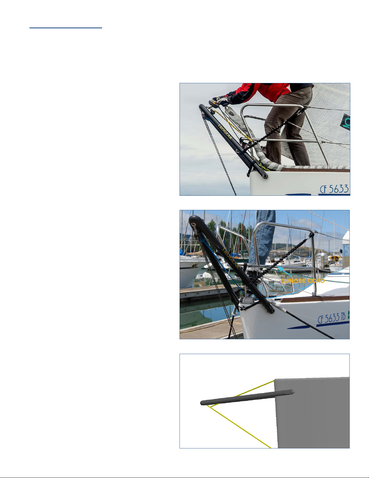
2. Adjustable Bowsprit – hinged aachment:
The Trogear bowsprit’s main design feature is the
hinged aachment, which allows it to rotate up and
down. We recommend a 2:1 Bobstay purchase with
the control line leading to a clutch and winch in the
cockpit. This allows you to take full advantage of
our unique design and adjust the sail lu tension
or bring the Bowsprit to an upright posion (for
stowing or changing sails only) (Fig. 13).
IMPORTANT NOTE: The Trogear Bowsprit should
be close to a horizontal posion when ying the
sails. See our use instrucons enclosed with your
purchase or online for more details.
A Bungee cord can be used to hold the Bowsprit in
an upright posion or pop it up when the bobstay is
released (similar in funcon to a Pole Topping li).
We recommend the MiniShockleTM from Davis but
others can be suitable as well. (Fig. 14)
Safety Measure: A method of prevenng the
bowsprit from pivong down past a predened
angle is needed in the event the sail drops to the
water.
Preventer Dyneema: The preventer should
be made from Dyneema and aached to the
headstay toggle and the lower fricon ring at the
p of the Bowpsprit. The length of the Dyneema
should be such that the sprit does not drop past
~20deg of horizontal when under tension. Think
of it as an inverted bobstay or a topping li on a
spinnaker pole. (Fig. 15)
See next page for more rigging details.
Fig 13: Bowsprit in upright posion to aach a furler.
Fig 14: Showing Bungee Cord and Stop Strap.
Fig 15: Preventer from Dyneema

Trogear Bowsprit Install Manual | www.trogear.com | info@trogear.com 7
1. U Bolt (shown here with low fricon ring)
2. Bobstay Dyneema - 2:1 purchase
3. Low fricon ring
4. Stainless steel ring for furler aachment or with block for tack line
5. Dyneema loop lead through the bowsprit bushing connects stainless steel ring (#4) and low fricon ring (#3)
6. Bobstay control line led through a clutch to a winch in the cockpit.
7. Bungee cord
1. Furler aached to stainless steel ring.
2. Block for tack line
3. Bobstay Dyneema
Rigging Example: (each yacht owner can congure the rigging that is most suitable for their needs.)
Table of contents
Popular Boating Equipment manuals by other brands


Bearon Aquatics
Bearon Aquatics Ice Eater P250 owner's manual

Taylor Made
Taylor Made Inflatable Quick-Shade Top instructions

Power-Pole
Power-Pole micro anchor Installation and owner's guide

Glendinning
Glendinning HoseMaster user manual

Bootzeil
Bootzeil ShapeX Motor Cruiser Installation instruction

EZZY SAILS
EZZY SAILS Infinity 2010 Rigging guide


