PROPER USAGE
• Do not use the equipment in any way other than as designed or intended by the manufacturer. It is
imperative that Trojan equipment is used properly to avoid injury.
• Injuries may result from exercising improperly or excessively.
• Your Trojan equipment should only be used by one person at a time.
• Be careful to maintain your balance while using, mounting, dismounting or assembling your Trojan
equipment to avoid injury.
• Do not attempt to adjust the seat or handlebars while you are on your Trojan equipment.
• Servicing other than the procedures in this manual should be performed by an authorised service
representative only.
INSPECTION
• Do not use or permit use of any equipment that is damaged or has worn or broken parts. For all Trojan
equipment use only replacement parts supplied by Trojan.
• Always make sure that all nuts and bolts are tightened prior to each use.
• Maintain labels and nameplates – do not remove labels for any reason.They contain
important information.
• Equipment maintenance – preventative maintenance is the key to smooth operating equipment. Please
ensure that you follow our maintenance tips to ensure the continued correct function of your
Trojan equipment.
• Before any use, examine all accessories approved for use with the Trojan equipment for damage or wear.
• Should your Trojan equipment appear damaged or worn, do not attempt to use or repair the
equipment yourself.
• Please contact our service department on 0861 TROJAN (0861 876526) to arrange a repair.
OPERATING WARNINGS
• It is the purchaser’s responsibility to instruct all users as to the proper operating procedures of all
Trojan equipment.
• Keep children away from all moving parts. Parents must provide close supervision of children if the
equipment is used in the presence of children.
• Do not wear loose tting clothing or jewellery when using the equipment. It is also recommended that
users tie up long hair to avoid contact with moving parts.
• Ensure that anyone not using the equipment stays clear of the user, accessories and moving parts while
the machine is in operation.
USER WEIGHT LIMITATIONS
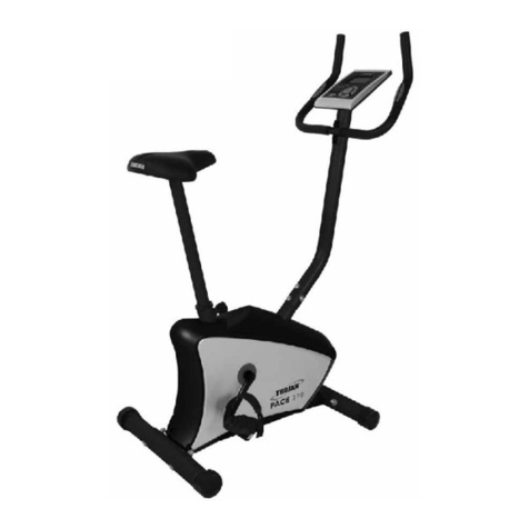
• This Trojan Surge 200 Exercise Bike may not be used by persons weighing more than 110 kg.
SAVE THIS INSTRUCTION MANUAL FOR FUTURE USE AND REFERENCE
If any of these instructions or warnings are unclear please contact Trojan Customer Services on
0861 TROJAN (0861 876526) within the Republic of South Africa or visit www.trojanhealth.co.za.


