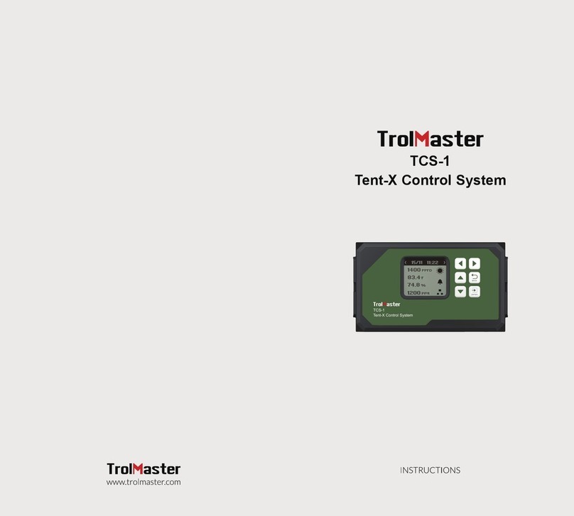
TrolMaster TCS-1 User manual

Tent-X Control System
TCS-1

OVERVIEW
Congratulations on purchasing the all in 1, state-of-the-art control
system, the Tent-X. Designed for single-zone grow tents, this device is
capable of satisfying all your grow tent’s environmental and irrigation
needs. The Tent-X is the brain that unites all your climate control devices
into one being, allowing your devices to work together in order to create
the optimal growth environment for your plants.
The TENT-X allows users to monitor and control both their environment
and the fertigation within their grow tent, using one simple-to-use and
cost-effective controller. The function of the Tent-X controller consists of
maintaining a tent at constant temperature and humidity, with the ability
to switch between Day and Night settings. It is also an irrigation tool,
allowing you to automatically keep the medium of the plants’ at your
desired settings.
INSTRUCTIONS
Install the Tent-X on a wall using the included back plate that comes in the
package with the controller. It is a simple fixed wall bracket. Simply release
the controller from the bracket by pulling the controller from the bracket,
then mount the bracket on the wall using screws. You can then place the
controller back into the bracket by simply pushing the controller into the
bracket. It will lock itself into place.
Install the MBS-TH sensor by plugging the sensor using the RJ12 cable
attached to the MBS-TH, into the sensor port on the Tent-X. Make sure
that the sensor is properly placed in the tent, perpendicular to the plants
and the grow lights. The MBS-TH is a 3-in-1 sensor that can detect
temperature, humidity, and light. In order to detect the PPFD levels of the
light being emitted, the MBS-PAR sensor has to be purchased separately.
It is recommended to install the controller in a clean and dry environment.
Do not allow the Tent-X to be exposed to water or excessive heat. Do not
open or attempt to open the Tent-X to repair or disassemble the
controller, as there are no user-serviceable parts inside. Opening the
controller will void the warranty. If you’d like to clean the surface of the
controller, wipe it with a damp cloth. The Tent-X operates under natural
ventilation conditions and is suitable to receive power from a
conventional household outlet.
*Reminder: The interconnecting RJ12 communication cables come in
various lengths. It's crucial to choose the right length that suits your
application. When purchasing the TCS-1 TENT-X Control System, you'll
receive a 4ft and 16ft cable as part of the package. However, if you need
longer cables, we also offer them in 25ft and 50ft lengths. Please ensure
that you select the appropriate cable length for your specific
requirements.
COMPONENTS
• Tent-X Controller
• Backplate(Bracket)
• 4ft RJ12 Cable
• Y-Shaped splitter
• 12DC Power supply
• 3-in-1 MBS-TH sensor
• 16ft RJ12 Cable
02 03

UP DOWN LEFT RIGHT ENTER BACK
BUTTONS ON THE TENT-X CONTROLLER
There are 6 buttons used for navigation on the controller:
Up/Down: Use the UP or DOWN button to navigate upwards or
downwards for any item on the LCD screen.
Left/Right: The LEFT and RIGHT buttons can either be used to navigate
across different pages or to select an item on the LCD screen
Enter: The ENTER button is used to open settings menu and to confirm
any selection that you’ve made.
Back: The BACK button is used to navigate back to previous pages.
The TENT-X controller comes with 5 rj12 ports, with each port having a
designated task.
1. Sensor Connections
All the sensors used with the TENT-X will be connected to the RJ12 port
labeled SENSORS, at the bottom of the unit. First, connect an RJ12 cable
to the port, then connect the other end to either a Y-splitter or
TrolMaster’s splitter hub (SPH-1). If using the Y-splitter, you can connect
the 3-in-1 MBS-TH sensor in one of the two ports and another sensor
such as the AMP-3 to the second port, or connect another Y-splitter to the
second port to create a daisy-chain connection in order to connect more
sensors.
For your environmental sensors, the Tent-X comes with a 3-in-1
temperature, humidity, and light sensor called the MBS-TH. Users can
daisy-chain the MBS-TH sensor with the CO2 sensor (MBS-S8), the full
spectrum quantum sensor (MBS-PAR), and the smoke and water
detectors called the MBS-SD and WD-1, into the Tent-X's SENSOR port.
In order to monitor your nutrients and grow medium data, connect the
AMP-3 sensor board to the TENT-X. Next, connect water content,
EC/temperature, and pH sensors, (WCS, PCT, and PPH sensors) to the
sensor board.
Once the sensors are all connected to the SENSOR port on the TCS-1,
press the small button on the sensors to link or “address” each sensor to
the TCS-1 controller. The TENT-X controller will then automatically
assigns an address to the sensors sequentially. Once the sensors are
addressed, the addresses will be saved unless the user completes a
factory or sensor reset within the system setting menu.
2. Light Connections
The TCS-1 can control most brands of LED or HID lights using the two
built-in lighting control channels on the TCS-1. Each of the two can
operate independently of each other to allow two different types or
brands of lights to be controlled, or to be able to split a grow room’s
lighting into two separate “zones”.
04 05

In order to control your lights, you must first plug in one of TrolMaster’s
Lighting Adapters into the RJ12 ports on the bottom of the controller,
labeled Line 1 and Line 2. TrolMaster offers several types of lighting
Adaptors for different brands and types of lights. If you have questions
about which adapter is correct for your lights, contact Tech Support or go
to TrolMaster’s website at www.trolmaster.com.
Since each of the two lighting control channels is independent, each line
can be set up to have its own timer settings and dimming temperature
setpoints as well as the dimming/power% that each group of lights will be
operated at.
3. Device Module Connections
All of the device modules used with the TCS-1 will be connected to the
RJ12 port at the bottom of the controller, labeled DEVICES. First,
connect an RJ12 cable to the port, then connect the other end to either a
Y-splitter or TrolMaster’s splitter hub (SPH-1). If using the Y-splitter, a
device module in one of the two ports and another device module to the
second port, or connect another Y-splitter to the second port to create a
daisy-chain connection in order to connect more device modules. Repeat
the procedure to collect all of the device modules to the DEVICES RJ12
port. Once the devices are all connected, press the small button on the
device modules to link or “address” each module to the TCS-1 controller.
The TENT-X controller will then automatically assign an address to the
device modules sequentially. Once the device modules are addressed, the
addresses will be saved unless the user completes a factory or device
reset in the system setting menu.
EC Fans connec tion:
In the Tent-X system, EC Fans can be controlled via the EFC-1 control
adaptors. Using the EFC-1 control adaptors, you can control 0-10-volt or
PWM-type EC fans, which you can select when first setting up the EFC-1.
The EFC-1 control adaptors can control the speed of the exhaust fan and
the intake fan, which as a result, can manipulate the temperature,
humidity, and negative pressure inside the grow tent to suit the users’
desired outcome.
4. Internet Connection
You can connect your TENT-X to the internet in order to have access to
remote monitoring, notifications, and control of your controller. To
connect the controller to your internet, TrolMaster recommends using a
hard-wired Cat 5/6 cable plugged into the Ethernet port on the bottom of
the TCS-1. After you have connected your TENT-X to the internet,
download TrolMaster’s app, TM+ Pro on your smartphone.
You can then access real-time data through your smartphone and have
remote control of the devices connected to the Tent-X, allowing freedom
to travel and be away from your growing environment. TrolMaster users
can also share their progress, interact with other growers, access
historical data and have access to many useful functions in the app.
*There is no built-in wifi on the TCS-1. Contact TrolMaster Tech Support
for options related to using a wifi connection as most commercially
available wifi range extenders (with Ethernet ports) are NOT compatible
with TrolMaster controllers.
First, plug in the Y-splitter that comes with your Tent-X. You then need to
plug two EFC-1 adaptors into the Y splitter RJ12 ports. Next, plug your
fans into the RJ12 port opening of the EFC-1 adaptors. Finally, address
each fan on the adaptors and establish the designated Intake and Exhaust
fans.
*If you are using more than one device in your grow tent, you can plug in a
Y-splitter into the device port and plug in a device into one of the ports on
the Y-splitter and plug in another Y-splitter into the second port, you can
keep repeating this procedure to create a daisy-chain connection to the
Tent-X in order to connect multiple devices. If you’d like a “cleaner” setup,
you can use TrolMaster’s 8-port splitter hub (SPH1) to connect multiple
devices to the Tent-X.
06 07

Setting
2
Humid
Temp
2
Setting
Day & Night
Climate
Light
Fan
Device
System
The alarm symbol only appears when there’s an alarm activated. The
internet symbol only appears when there’s internet connectivity.
12
4
1
5
13
2
6
10
14
3
7
11
15
9
8
16
Reservoir pH
level
Reservoir Electrical
Conductivity
Temperature
Humidity
Parts Per Million
Photosynthetic
Alarm activated
Internet
connected
Reservoir
temperature
Reservoir
Grow Medium
Medium
Electrical Conductivity
Medium
temperature
Medium Water
Content
Night mode
Day mode
02/06 09:30
83.4 F
74.8 %
1200 PPM
800 PPFD
1
2
3
7
8
4
02/06 09:30
1.36 mS/cm
3.17 mS/cm
73.0 F 7.94 pH
57.4 F65 %
10
11
14
15
12
16
13
9
6
5
MAIN INTERFACE
When you plug in the Tent-X for the first time, you will land on the
homepage on the LCD display. This is where the sensor data for the grow
tent is displayed. Press the “LEFT” and “RIGHT” arrows to switch between
the climate parameter data, the nutrients and grow medium monitoring
data, the device status page, and the alarm notification page. Each page
provides specific information about the Tent-X.
The Tent-X will constantly monitor your climate, and nutrients and grow
medium data in real-time:
Temporary demonstration:
Alarm notifications
The alarm notification page is where all of your alarm notifications are
consolidated. This is where you can check up on missed alarm
notifications, and adjust your set-up accordingly.
Device Status
The Device Status page is where you can view the status of all your
devices connected to the TENT-X, whether it’s climate control devices or
timer-controlled devices for irrigation. If a device is not working in your
grow tent, you can check the connectivity status on this page.
Climate control
When you press ENTER on the Tent-X, you will enter a setting page
consisting of five blocks, with each block serving a unique function for
climate control. The “Day&Night Climate” tab is where you can set the
climate parameters for the grow tent. The “Light”, “Devices”, and “Fans”
tabs are where you assign devices that can alter the climate in the grow
tent.
Day&Night Climate
After pressing ENTER on the Day&Night Climate tab, you will land on a
page where you can set the temperature, humidity, and CO2 in the grow
tent, for both day and night times. After the climate parameters have been
set, the climate devices connected to the Tent-X will automatically
maintain that temperature. You can also set alarms for your climate
parameters, in case the parameters are not within the set range.
08 09

CO2 Setting
Climate Setting
Alarm Offset
Day
33
60
1200
Temp
Humid
CO2
C
%
PPM
Night
36
55
500
Light
After pressing ENTER on the Light block, the screen will display Line 1
and Line 2. Use the UP and DOWN arrows to choose Line 1 or Line 2 and
press ENTER to navigate to the page where you can make changes to the
selected Line.
On this page, you can create your light settings. Use the UP and DOWN
buttons to navigate the options on this page and press ENTER on an item
to change it. When you see the item blinking, you can switch between the
selections using the UP and DOWN arrows. When you have selected your
item, press ENTER again to confirm the selection. Select whether you’re
using HID or LED lights. You can also select the On/Off time for your
lights, the temperature at which the lights will dim, the Sunrise and Sunset
time, and more.
Devices
The Devices tab is where you will set up your climate control devices.
With the use of our plug-in DS modules, you can connect and control the
devices via the controller. Each DS module has a designated function. The
DST module can only control temperature devices, the DSH module can
only control humidity devices, the DSC module can only control CO2
devices, and the DSP module is a multi-function module that works as a
timer. TrolMaster’s Tent-X controller allows up to 8 four plug-in modules
to be connected to the Tent-X. Two of the 8 available slots are reserved
for temperature control, 2 are for humidity control and 4 are for
timer-controlled devices like pumps or solenoids. Users are free to
connect whatever device they’d like to connect, whether it’s more climate
control devices or irrigation devices. Go to trolmaster.com for more
information.
Press ENTER to access the device's settings. You can set up 2 climate
control devices each for temperature, humidity, and CO2. You will then
see 2 columns, with each column representing one of two devices for each
climate parameter. You can also set 4 program devices, labeled from P1 to
P4.
In the device setting menu, press ENTER on any of the climate devices and
it will start blinking. You can then use the UP or DOWN arrows to select
what kind of device is connected to the Tent-X.
When you have finished selecting the device you’ve connected for each
element, press ENTER again to confirm the selections.
Go to the “Alarm Offset” tab and press ENTER. You will then see the value
for every alarm setting displayed. After pressing ENTER on a parameter,
the unit will blink. Use the UP and DOWN arrow to set the range for your
alarm setting, and press ENTER again to confirm. When the temperature,
humidity, and CO2 levels exceed or fall below the set range, you will get an
alarm notification on your Tent-X and on our smartphone app TM+ PRO.
When the temperature, humidity, and CO2 levels exceed the set range,
you will get an alarm notification on your Tent-X and on our smartphone
app, TM+ PRO.
10 11
Setting
Lighting
Line 1
Line 2
Setting
Line 1 Lighting
Mode LED
08:00
100%
84 oF
20:00
89 oF
OFF
Power
On at
Off at
Dim at
Stop at
Sun R/S time

Setting
Setting
Day & Night
Climate
Light
Fans
Devices
System
EC Fans
Users can control two EC fans at the same time, categorized as F1 and F2.
The first fan, F1, can be used and controlled as an exhaust fan to control
temperature and humidity. The second fan, F2, can be used and controlled
as an intake fan to create the desired negative pressure in the grow tent.
F1: There are 4 modes for the F1 fan. These 4 modes include:
• Cool only mode: The exhaust fan is solely controlled by the temperature
in the grow tent
• Dehu only mode: The exhaust fan is solely controlled by the humidity
levels in the grow tent
• Cool priority mode: The exhaust fan is controlled by both temperature
and humidity, however, it will prioritize temperature to be within the
defined range if both can’t be achieved.
• Dehu Priority mode: The exhaust fan is controlled by both temperature
and humidity, however, it will prioritize humidity to be within the defined
range if both can’t be achieved.
Within the F1 setting page, you can also set the minimum and maximum
fan speed the exhaust fan can operate at. Setting the minimum speed for
the fan to operate will allow the user to ensure negative pressure even
when the tent is not calling for cooling, and setting the maximum speed
the fan can operate will allow the user to choose how fast and how loud
the fan will operate at full speed.
The program device modules can be used to connect either more climate
devices or timer-based irrigation devices like solenoids and pumps. If you
want to connect irrigation devices to set up irrigation schedules, you can
use the DSP modules to set up your preferred schedules.
In order to program a device by schedule, press ENTER on any of the
program tabs from P1 to P4. The LCD screen will then display 3 options,
where you can set what kind of schedule you’d like to set.
If you choose the single schedule setting, there are only 2 inputs you’ll
have to do, where you simply input when the device turns on, and when it
turns off.
If you choose the multi-schedule setting, you can set up to 12 individual
On and Off times for each device to follow within a 24-hour “day”.
If you choose to use the recycle timer mode, you will be able to determine
the On and Off time duration, and the recycle timer mode will then repeat
that same On / Off duration schedule as many times as you’d like, working
as a repeat-cycle timer. You will also be able to select the time of day for
the repeat-cycle to begin, as well as be able to determine how many cycles
will be repeated before the timers are shut off until the next day.
The Tent-X controller will handle the rest once you've set up your
preferred irrigation schedule. Your timer-controlled devices will be
controlled automatically with the TCS-1 according to the settings you
specified.
Devices Setting
T-1
Heat T-2
Cool
H-2
Dehumid
C-2
Out
H-1
Humid
C-1
In
P-1 P-3P-2 P-4
12 13
Setting
2
Humid
Temp
2
Setting
Exhaust Fan
(F1)
Intake Fan
(F2)

Setting
Setting
Intake Fan
(F2)
Exhaust Fan
(F1)
CO2 Interlock
The CO2 interlock function is a powerful tool to preserve your CO2
supply. When the CO2 interlock function is toggled on, CO2 will not be
injected into the grow tent when the fans are activated.
F2: The user can customize their intake fan settings within the F2 block.
While a single exhaust fan can be used, we can control the amount of
negative pressure within the tent by adding a separate intake fan and
controlling it separately. With the F2 option, you can set the negative
pressure in your tent by decreasing the speed of the intake air fan. Press
ENTER on “Intake Fan(F2)” and you will land on the page where you can
set the negative pressure you’d like in your grow tent. Press ENTER again
and use the UP and DOWN arrows to select your number, press ENTER
again to confirm the selection.
You also have the option to not let your intake fan activate when your
temperature and/or humidity falls below the setpoints. This function will
run in conjunction with the F1 settings and gives you the ability to choose
whether you want to run the F2 fan at minimum speed % or turn the fan
off completely. Press ENTER on the bottom square and it will start
blinking. Use the UP or DOWN arrow to allow the check mark √to
appear on the screen, and press ENTER again to confirm the selection.
With the TENT-X, the fan is constantly monitoring the temperature and
humidity inside the tent. Depending on how you set it up, the fans will
then increase their speed as the temperature or humidity rises, and they
will slow down as the temperature and humidity decrease. With the fans
working together in an "open loop" control scheme, you will be able to
accurately control the environment inside the tent using fresh air.
System Settings
The “System” tab is where you will set your miscellaneous internal settings
for your Tent-X Controller. This is where you can set what format you’d
like your unit of measurements to be for temperature and EC, and your
time settings.
You can also manually override your controller on this page if you’d like to
test and make sure everything is connected and working properly with the
controller, as well as scan the QR code to pair your smart device with the
controller, or do a complete system reset if there’s a need to do so.
In addition, you can calibrate the various sensors you are using inside the
grow tent. Furthermore, on the System page, you can set your deadband
setpoints that will be used with your connected DS modules. The
deadband settings determine when each module will turn on, and turn off
again.
Moreover, Set the ADJUSTABLE VARIABLE RANGE for your
temperature and humidity in the EC Fan Settings tab. Its purpose is to
allow the exhaust fan to start operating at the maximum speed set by the
user in the F1 settings when the temperature or humidity exceeds five
degrees Fahrenheit, three degrees Celcius, or 5% humidity of the user's
original setpoints. As the temperature or humidity drops back to the
climate setpoint, the fan will gradually resume to the minimum speed set
by the user in a linear fashion.
Lastly, you can set your Water detectors in case of leakage or water
confirmation, and your WD delay time., On the Alarm setting page, you
can set your high and low limit alarm settings for your climate, nutrients,
and grow medium. When the values exceed or drop below the defined
Maximum and Minimum setpoint in the alarm settings, you will
immediately be notified on the controller and through TrolMaster’s app,
TM+ Pro.
12 13

SPECIFICATIONS
WARNING :
DO NOT allow the TCS-1 Dry Contact Board to be
exposed to water or excessive heat. DO NOT open or attempt to
repair or disassemble the controller, as there are no
user-serviceable parts inside. Opening the controller will void the
warranty.
If the surface of TCS-1 Dry Contact Board is dirty, wipe it with a dry
towel. The TCS-1 Dry Contact Board operates under natural
ventilation conditions.
AVERTISSEMENT :
NE PAS exposer la carte de contact sec TCS-1 à
l'eau ou à une chaleur excessive. NE PAS ouvrir ou tenter de réparer
ou de démonter le contrôleur, car il ne contient aucune pièce
réparable par l'utilisateur. L'ouverture du contrôleur annulera la
garantie.
Si la surface de la carte de contact sec TCS-1 est sale, essuyez-la
avec une serviette sèche. La carte de contact sec TCS-1 fonctionne
dans des conditions de ventilation naturelle.
Input Voltage
Certifctions
MBS-S8 (CO2) :
MBS-PAR (PPFD) :
MBS-SD (Smoke Detector) :
AMP-3 (pH / EC / Temp) :
WCS-1/2 (WC / EC / Temp):
WD-1 (Water Detector)
Temperature Device Stations:
Humidity Device Stations:
CO2 Device Stations:
Timer Device Stations:
EC Fan Control Adpator:
Working Environments
100-240VAC, 50/60Hz
ETL/FCC
max 1pc per set
MBS-TH (Temp / Humid / Light) : max 1pc per set
max 1pc per set
max 1pc per set
max 1pc per set
max 1pc per set
max 2pc per set
max 2pc per set
max 2pc per set
max 2pc per set
max 4pc per set
max 2pc per set
Temperature 32-122°F, Humidity≤90%
12 13
Table of contents
Other TrolMaster Control System manuals
Popular Control System manuals by other brands

CALEFFI
CALEFFI 210510 Installation and commissioning manual

TECSYSTEM
TECSYSTEM VRT300 Series instruction manual

H2flow
H2flow levelsmart User instruction manual

American Standard
American Standard AccuLink Platinum 1040 Installation & user guide

Siemens
Siemens tiastar MCC installation instructions

Emec
Emec DIN DIGITAL CD operating manual