Tronair 04-6152-0120 Installation and operating instructions

OPERATION & SERVICE MANUAL
Tronair, Inc. Phone: (419) 866-6301 | 800-426-6301
1 Air Cargo Pkwy East Web: www.tronair.com
Model: 04-6152-0120
Utility Crane
09/2017 Rev. 02

REVISION DATE TEXT AFFECTED
01 08/2008 Original Release
02 09/2017 Modified Parts List

04-6152-0120
Utility Crane
09/2017 | Rev. 02
TABLE OF CONTENTS PAGE
1.0 PRODUCT INFORMATION ..............................................................................................................................................1
1.1 DESCRIPTION....................................................................................................................................................1
1.2 MODEL & SERIAL NUMBER..............................................................................................................................1
1.3 MANUFACTURER..............................................................................................................................................1
2.0 SAFETY INFORMATION..................................................................................................................................................1
2.1 USAGE AND SAFETY INFORMATION..............................................................................................................1
3.0 TRAINING.........................................................................................................................................................................1
3.1 TRAINING REQUIREMENTS.............................................................................................................................1
3.2 TRAINING PROGRAM .......................................................................................................................................1
3.3 OPERATOR TRAINING......................................................................................................................................1
4.0 SPECIFICATIONS ............................................................................................................................................................2
5.0 FEATURES.......................................................................................................................................................................3
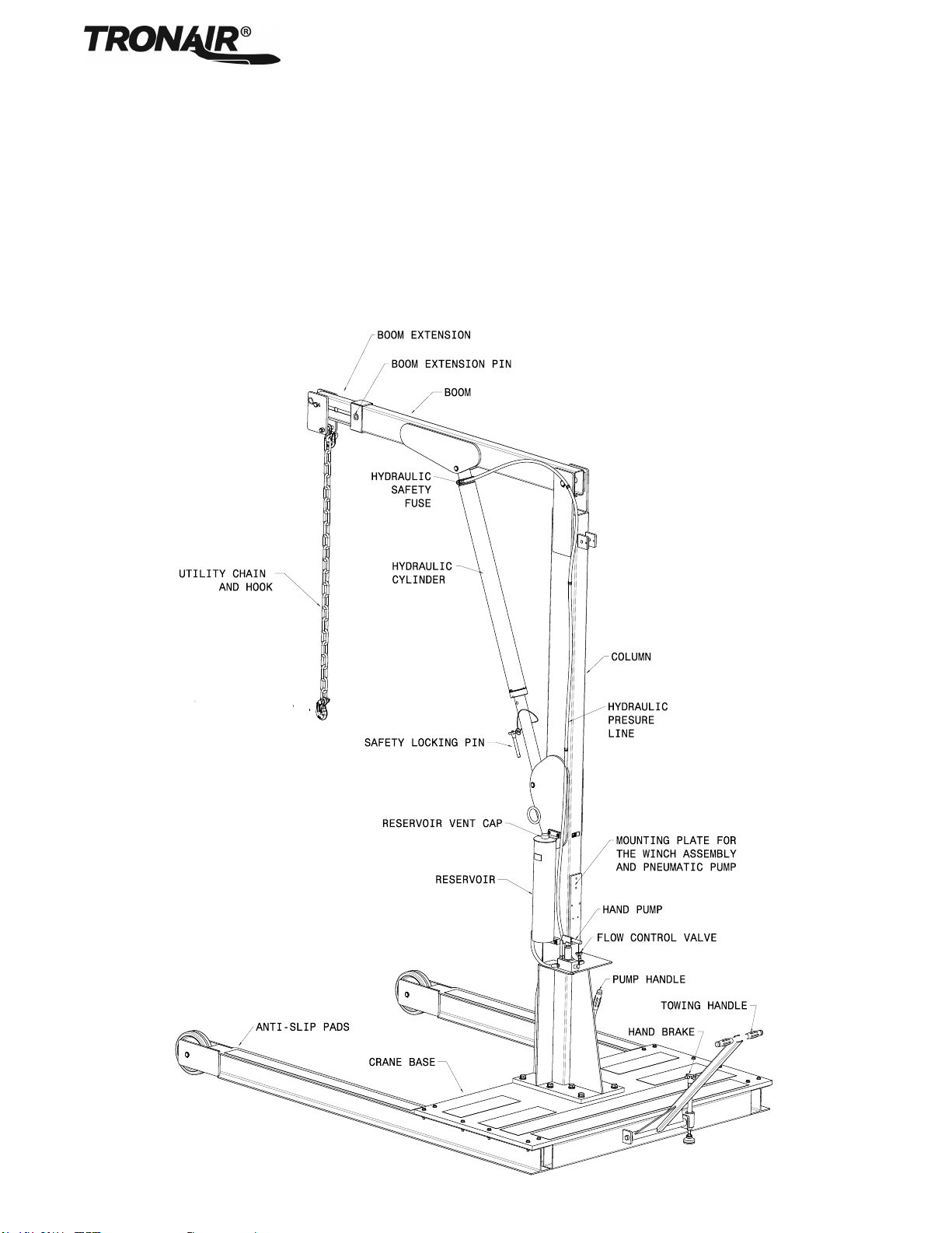
5.1 OPERATOR CONTROLS AND PARTS..............................................................................................................3
5.2 OPTIONAL FIELD INSTALLED KITS .................................................................................................................4
6.0 PREPARATION FOR USE ...............................................................................................................................................4
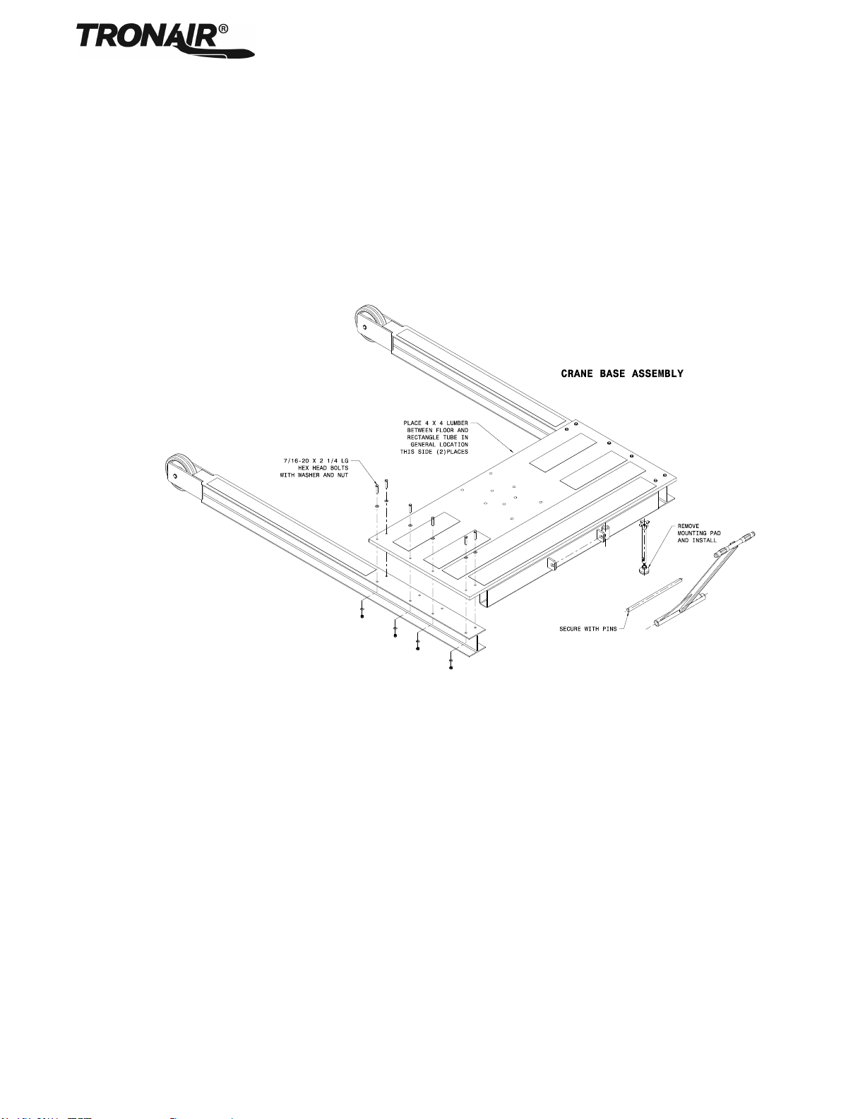
6.1 CRANE ASSEMBLY...........................................................................................................................................4
6.1.1 Crane Base Assembly.........................................................................................................................................4
6.1.2 Column and Boom Assembly..............................................................................................................................5
6.2 CRANE OPERATION .........................................................................................................................................5
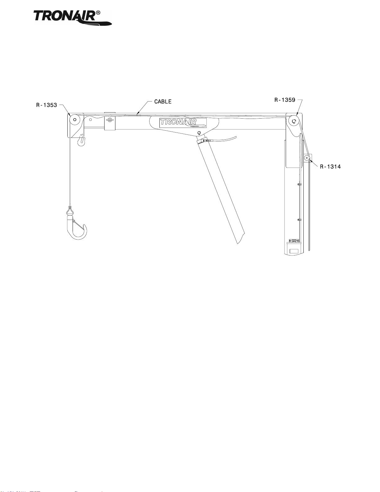
7.0 WINCH KIT (K-2953 OPTION)..........................................................................................................................................6
7.1 TECHNICAL SPECIFICATIONS.........................................................................................................................6
7.2 INSTALLATION...................................................................................................................................................7
7.3 OPERATION.......................................................................................................................................................7
7.3.1 To Pull the Cable In or Raise the Load ...............................................................................................................7
7.3.2 To Let Cable Out or Lower the Load...................................................................................................................7
8.0 PNEUMATIC PUMP KIT (K-2013 OPTION).....................................................................................................................8
8.1 INSTALLATION...................................................................................................................................................8
8.2 OPERATION.......................................................................................................................................................8
9.0 GOOSENECK KIT (K-2012 OPTION)...............................................................................................................................9
9.1 INSTALLATION...................................................................................................................................................9
10.0 INSPECTION/MAINTENANCE.......................................................................................................................................10
10.1 INITIALINSPECTION .......................................................................................................................................10
10.2 BEFORE EACH USE........................................................................................................................................10
10.3 PERIODIC INSPECTION..................................................................................................................................11
10.4 ANNUAL INSPECTION.....................................................................................................................................11
10.4.1 CRANE INSPECTION & TESTING REQUIREMENTS.....................................................................................11
11.0 PROVISION OF SPARES...............................................................................................................................................12
11.1 SOURCE OF SPARE PARTS...........................................................................................................................12
11.2 RECOMMENDED SPARE PARTS LISTS ........................................................................................................12
12.0 IN SERVICE SUPPORT..................................................................................................................................................12
13.0 GUARANTEES/LIMITATION OF LIABILITY..................................................................................................................12
14.0 APPENDICES.................................................................................................................................................................12

04-6152-0120
Utility Crane
09/2017 | Rev. 02 Page | 1
This product can not be modified without the written approval of Tronair, Inc. Any modifications done without written approval
voids all warranties and releases Tronair, Inc., it suppliers, distributors, employees, or financial institutions from any liability
from consequences that may occur. Only Tronair OEM replacement parts shall be used.
1.0 PRODUCT INFORMATION
1.1 DESCRIPTION
The Tronair heavy duty utility crane is designed to handle many lifting tasks required in aviation maintenance facilities, such as
engine changes, stabilizer removal, etc.
1.2 MODEL & SERIAL NUMBER
Reference nameplate on unit
1.3 MANUFACTURER
TRONAIR, Inc. Telephone: (419) 866-6301 or 800-426-6301
1 Air Cargo Pkwy East Fax: (419) 867-0634
Website: www.tronair.com
2.0 SAFETY INFORMATION
2.1 USAGE AND SAFETY INFORMATION
To insure safe operations please read the following statements and understand their meaning. Also refer to your equipment
manufacturer’s manual for other important safety information. This manual contains safety precautions which are explained
below. Please read carefully.
WARNING! —Warning is used to indicate the presence of a hazard that can cause severe personal injury,
death, or substantial property damage if the warning notice is ignored.
CAUTION! —Caution is used to indicate the presence of a hazard that will or can cause minor personal injury
or property damage if the caution notice is ignored.
3.0 TRAINING
3.1 TRAINING REQUIREMENTS
The employer of the operator is responsible for providing a training program sufficient for the safe operation of the unit.
3.2 TRAINING PROGRAM
The employer provided operator training program should cover safety procedures concerning use of the unit in and around the
intended aircraft at the intended aircraft servicing location.
3.3 OPERATOR TRAINING
The operator training should provide the required training for safe operation of the unit.
NOTE: Maintenance and Trouble Shooting are to be performed by a skilled and trained technician.

04-6152-0120
Utility Crane
09/2017 | Rev. 02 Page | 2
4.0 SPECIFICATIONS
Minimum Length: 117 in (297.2 cm)
Width: 78 in (198.2 cm)
Minimum Height: 156 in (396.2 cm)
Weight: 2,399 lbs (1,088 kg)
Standard Boom
Position
Maximum
Load
lbs (kg)
Maximum
Height
in (cm)
Extension
“BL”
in (cm)
1
1350 (612)
231 (541)
115.25 (293)
2
1850 (839)
227 (577)
108.25 (275)
3
2200 (998)
223 (566)
101.25 (257)
4
2500 (1134)
219 (556)
94.25 (239)
5
2750 (1247)
215 (546)
87.25 (222)
6
2750 (1247)
211 (536)
80.25 (204)
7
2750 (1247)
207 (526)
73.25 (186)
Gooseneck Boom
Position
Maximum
Load
lbs. (kg)
Maximum
Height
in (cm)
Extension
“BL”
in (cm)
1
500 (227)
292 (741)
197 (500)
2
560 (254)
288 (731)
190 (482)
3
600 (272)
284 (721)
183 (464)
4
640 (290)
280 (711)
176 (447)
5
700 (317)
276 (701)
169 (429)
6
750 (340)
272 (690)
162 (411)
7
800 (363)
268 (680)
155 (393)
WARNING!
Load ratings listed above are valid for non-winch applications ONLY.
Reference section 5.1 Technical Specifications of 5.0 Winch Kit Operation for the appropriate safe load
conditions listed above.

04-6152-0120
Utility Crane
09/2017 | Rev. 02 Page | 3
5.0 FEATURES
Heavy duty base provides required counter-weight for safe lifting
Clean design allows maximum workroom
Conveniently located controls
Positive holding hand break
Heavy duty bearing swivel casters and wheels
Built in handle for easy movement
Safety fuse prevents load dropping in case of hydraulic failure
Safety locking pin allows eight (8) locking positions on cylinder rod
Blue powder coated
5.1 OPERATOR CONTROLS AND PARTS
See illustration

04-6152-0120
Utility Crane
09/2017 | Rev. 02 Page | 4
5.0 FEATURES (continued)
5.2 OPTIONAL FIELD INSTALLED KITS
K-2012 Kit, Gooseneck:
The Gooseneck is an extension to the main boom. The Gooseneck increases the overall maximum height of the crane to 275
inches (698 cm). (Reference Parts List page 15)
K-2013 Kit, Pneumatic Pump:
The pneumatic pump uses shop air to raise the main boom. (Reference Parts List page 14)
K-2953 Kit, Winch:
This hand winch kit allows loads to be lifted & lowered vertically, independently of boom, through use of an easy-to-operate
hand winch. The winch can be used with or without the Gooseneck kit. (Reference Parts List page 13)
6.0 PREPARATION FOR USE
The unit is shipped complete with the base partially assembled, and only the following steps are required to make the crane
operational:
6.1 CRANE ASSEMBLY
6.1.1 Crane Base Assembly
Step 1 Unpack all components and inspect parts.
Step 2 Using lift truck, crane or equivalent, place crane base on flat ground with front end of base supported by two 4” x 4”
pieces of lumber (supplied, part number W006-01*012.0) under front base tube.
Step 3 Position legs under both sides of base and align holes. There are six (6), 7/16 x 2 ½” long, bolts used to secure each
leg to the base.
NOTE: There are eight (8) holes in the leg, only six (6) will be used per side.
Starting from the rear of each leg, install bolt with washer through base and leg assembly, secure with washer and
elastic stopnut. C-clamps or equivalent may be necessary to help draw leg assembly to bottom of base. After all six
nuts and bolts are installed and hand-wrench tight, start from back of base, working to the front, torque bolts to 54 ft-
lbs. (73.2 nm). Repeat for other leg. Remove lumber supports and let base rest on ground.
Step 4 Install tow handle using one inch (1") bar and cotter pins.
Step 5 Install hand brake screw rod into base and install pad onto screw drive.
6.1 Crane assembly continued on following page.

04-6152-0120
Utility Crane
09/2017 | Rev. 02 Page | 5
6.1 CRANE ASSEMBLY (continued)
6.1.2 Column and Boom Assembly
Step 1 Install column assembly onto base, using eight (8) ¾ inch bolts with flatwashers and lockwashers. Torque to 380 ft-
lbs (515 nm).
NOTE: If winch kit is included with crane review section 5.2 BEFORE proceeding.
Step 2 Install main boom onto column using 1¼ inch pin and lock rings.
Step 3 Connect cylinder to boom using one inch (1") pin and lock rings.
6.2 CRANE OPERATION
Step 1 Fill reservoir to within one inch (1") of top with mineral base hydraulic fluid.
Step 2 Position boom extension to desired position.
Step 3 See chart located on crane column for loading and height information.
Step 4 Close flow control valve and pump to raise the main boom.
Step 5 Open flow control valve to lower main boom.

04-6152-0120
Utility Crane
09/2017 | Rev. 02 Page | 6
7.0 WINCH KIT (K-2953 OPTION) WARNING!
The winch is of general purpose design for manual operation only and the load rating is based on an
intermittent duty cycle. The winch is not designed to be a human hoist and should never be operated
when there are persons positioned on or under the load being lifted.
Obey crank rotation instructions. Disregarding these instructions could cause bodily harm or property
damage. When facing the crank handle side of the winch, crank clockwise to lift the load, counter-
clockwise to lower the load. Never release the crank handle unless the ratchet pawl is fully engaged
and supporting the load.
NEVER exceed the rated capacities shown on the winch frame.
Never exceed the boom rated capacities shown under section 2.0.
Maintain a minimum of four (4) wraps of cable on the drum at all times.
WARNING!
NEVER use worn, kinked or frayed cable. These conditions are unsafe. Replace the cable immediately
with Tronair certified cable only!
Always inspect the cable and hook before each use to make sure they are not damaged. If the cable or
hook breaks, the cable can act like a whip and inflict serious damage to anyone in its path.
NEVER stand along side the winch cable, or guide the cable with your hands.
NEVER permit anyone on or under the load that is being lifted.
NEVER operate with wet or oily hands and always use a firm grip on the handle.
NEVER leave a weight hanging by the winch while the winch is unattended, as unauthorized persons
may attempt to operate the winch, thereby creating an unsafe condition.
NEVER use crane if any damage or excessive wear is found.
NEVER make any alterations or modifications to crane.
CAUTION!
Tether load to keep the load from swinging.
ALWAYS stay clear of suspended loads.
NEVER use sling to lift personnel.
NEVER leave suspended loads unattended.
NEVER remove or obscure warning labels.
DO NOT use crane until you have read and understood this manual.
NEVER lift loads higher than necessary.
7.1 TECHNICAL SPECIFICATIONS
NOTE: Read Thern’s Owner’s Manual for complete technical specifications and instructions on winch use and its
operation (Thern winch model # M452B-A).
Maximum capacity 3000 lbs (1360.7 kg)
Cable: 5/16 inch diameter, 7x19 Aircraft (8 mm)
19.5:1 gear ratio, Maximum mechanical advantage 101:1
Automatic load holding break system.
When cranking counter-clockwise, this winch incorporates a mechanical brake bypass system that winds cable off the drum
when the load is very light. The brake will reset when the load is increased.
7.0 Winch Kit (K-2953 Option) continued on following page.

04-6152-0120
Utility Crane
09/2017 | Rev. 02 Page | 7
7.0 WINCH KIT (K-2953 OPTION) (continued)
7.2 INSTALLATION
Step 1 Attach cable to winch per INS-1517 supplied with winch kit.
Step 2 Install pulley at end of beam extension, install pulley on column and beam intersection.
Step 3 Bolt winch plate to crane with 3/8 inch bolts. Torque to 49 ft-lbs (66 nm).
Step 4 Bolt winch to winch plate using ½ inch bolts. Torque to 120 ft-lbs (163 nm)
Step 5 Run 5/16 inch diameter cable into front end of main boom over pulleys.
Step 6 Secure cable on drum as shown in INS-1517.
Standard Boom Cable Routing
7.3 OPERATION
The brake is actuated by turning the handle. The load-lock brake is designed to hold the load whenever the handle is released.
7.3.1 To Pull the Cable In or Raise the Load
1. The cable must be securely fastened to the object being lifted and to the winch drum.
2. Always be sure that the cable and cable attachments are not damaged.
3. Crank handle clockwise to lift, making sure the clicking sound of the ratchet is heard.
7.3.2 To Let Cable Out or Lower the Load
1. Crank the handle counter-clockwise. No clicking sound will be heard because the load-lock braking system is now
activated.

04-6152-0120
Utility Crane
09/2017 | Rev. 02 Page | 8
8.0 PNEUMATIC PUMP KIT (K-2013 OPTION)
8.1 INSTALLATION
Refer to illustration below:
Step 1 Lower boom to lowest position.
Step 2 Disconnect pressure line to cylinder from hand pump.
Step 3 Mount pneumatic pump to column.
Step 4 Attach and tighten fitting from pneumatic pump to hand pump.
Step 5 Attach and tighten fitting from pressure hose from cylinder to fitting on pump.
Step 6 Use “C” clamp or vise grip to pinch line near reservoir. Cut reservoir return line, catch expelled fluid, and install tee
union fitting.
Step 7 Tighten and secure all pressure fittings.
Step 8 Connect shop air [125 psi maximum (8.6 bar)] input. Pneumatic pump is ready to use.
Pneumatic Pump Assembly
8.2 OPERATION
Step 1 Connect shop air into pneumatic pump inlet [125 psi (86 bar) max input].
Step 2 Open flow control valve, open shut off valve and squeeze handle to raise main boom.
Step 3 Release handle when main boom is in desired position, close control valve and close air supply valve.
Step 4 Open flow control valve to lower main boom.

04-6152-0120
Utility Crane
09/2017 | Rev. 02 Page | 9
9.0 GOOSENECK KIT (K-2012 OPTION)
9.1 INSTALLATION
Step 1 Remove pulley at front end of boom extension.
Step 2 Unreel approximately 15 feet (4.5 m) of cable from winch.
Step 3 Install gooseneck into end of beam extension, running cable through the slot in gooseneck.
Step 4 Pin gooseneck into position at end of beam extension. See Figure of Goose Neck Cable
Gooseneck Cable Routing
Cable Routing with Optional K-2953 (Winch Kit)
CAUTION!
Always slide goose neck completely in boom extension & secure with pin.
Failure to use correct position will jeopardize load rating
Step 5 Run cable under first pulley on gooseneck and run cable over second and third pulleys on the gooseneck.
Step 6 Position boom extension into desired position and lift load.
Step 7 See and follow load capacity chart on crane column.

04-6152-0120
Utility Crane
09/2017 | Rev. 02 Page | 10
10.0 INSPECTION/MAINTENANCE
To keep your Tronair equipment fully operational and last for years you should adhere to the following suggestions which
conform to the requirements of ASME B30.20.
If testing cannot be done safely and properly, it is recommended to send Equipment to Manufacturer or Authorized
Service Center for Recertification.
All new, altered, modified, or repaired lifting devices shall be tested andinspected before use. It is recommended that
the results of the test and inspection shall be documented in an equipment historyfile.
10.1 INITIALINSPECTION
Prior to their initial use, a qualified inspector shall inspect all new, modified, or repaired lifting devices to ensure compliance
with Section 10.3 PERIODIC INSPECTION
10.2 BEFORE EACH USE
The operator or other designated person shall visually inspect each lifting device at the beginning of each shift or prior to use,
if it has not been in regular service, for the following items or conditions:
Visually inspect unit to ensure all components are present and functional
Loose or missing guards, fasteners, covers, stops, or nameplates
All pivot bolts & nuts are secure
Cylinder is free of leaks & relief valve is operational
All casters & locks are operational
No bent, broken or corroded components
Structural deformation, cracks, or excessive wear on any part
Ensure cable is free of corrosion, damage and fraying
All operating mechanisms and automatic hold-and-releasemechanisms for maladjustments interfering with operation
WARNING!
NEVER use worn, kinked or frayed cable. These conditions are unsafe. Replace the cable immediately with
Tronair certified cable only!
WARNING!
Ensure lift components are free of damage and or excessive wear. Never use lift if any component is bent
or broken
The operator or designated person shall carefully examine any deficiencies and determine whether they constitute a hazard.
Deficiencies noted during the inspection shall be corrected before the lifting deviceis used.
10.0 Inspection/maintenance continued on following page.

04-6152-0120
Utility Crane
09/2017 | Rev. 02 Page | 11
10.0 INSPECTION/MAINTENANCE (continued)
10.3 PERIODIC INSPECTION
A qualified inspector shall performa complete inspection at the following intervals
SERVICE
INTERVAL
Normal
Yearly
Inspect equipment at site of use. Operation with various weights within the rated load limit,or
uniform loads less than 65 percent of rated load.
Heavy
Semi-Annual
Inspect equipment at site of use unlessexternal conditions indicate that disassembly should
be done to permit detailed inspection. Operation within the rated load limit that exceeds
normalservice.
Severe
Quarterly
Inspect equipment at site of use unlessexternal conditions indicate that disassembly should
be done to permit detailed inspection. Operation at normal or heavy service under abnormal
operating conditions.
Special/
Infrequent
As recommended by a qualified person before the first such use and as directed by the qualified person for
any subsequent uses
1. Visually inspect unit to ensure all components are present and functional
Loose or missing guards, fasteners, covers, stops, or nameplates
All pivot bolts & nuts are secure
Cylinder is free of leaks & relief valve is operational
All casters & locks are operational
No bent, broken or corroded components
Structural deformation, cracks, or excessive wear on any part
Ensure cable is free of corrosion, damage and fraying
All operating mechanisms and automatic hold-and-releasemechanisms for maladjustments interfering with operation
2. Lubricate lift
All pivot points
Threaded adjustment areas
3. Check cylinder reservoir level. Replenish with MIL-5606
Ensure Fluid is at acceptable level
Flush reservoir if fluid is contaminated
10.4 ANNUAL INSPECTION
Ensure lift has been load certified to not more than 125% of rated load capacity. Check for applicable codes for requirements
on annual load testing/certifications.
1. Visually inspect unit to ensure all components are present and functional
Loose or missing guards, fasteners, covers, stops, or nameplates
All pivot bolts & nuts are secure
Cylinder is free of leaks & relief valve is operational
All casters & locks are operational
No bent, broken or corroded components
Structural deformation, cracks, or excessive wear on any part
Ensure cable is free of corrosion, damage and fraying
All operating mechanisms and automatic hold-and-releasemechanisms for maladjustments interfering with operation
2. Lubricate lift
All pivot points
Threaded adjustment areas
10.4.1 CRANE INSPECTION & TESTING REQUIREMENTS
Section 1910.179 of the U.S. Department of Labor Occupational Safety & Health Administration Standards lists the testing
requirements and specifics relating to crane inspection and testing.
In particular sections 1910.179 (j)(1)(ii) addresses inspection time frames as well as Section 1910.179 (j)(2) and (j)(3).
Section 1910.179 (k) provides information regarding load testing.
All of the requirements in Section 1910.179 should be strictly followed for proper operation and safety of utility crane
equipment.

04-6152-0120
Utility Crane
09/2017 | Rev. 02 Page | 12
11.0 PROVISION OF SPARES
11.1 SOURCE OF SPARE PARTS
Spare parts may be obtained from the manufacturer:
TRONAIR, Inc. Telephone: (419) 866-6301 or 800-426-6301
1 Air Cargo Pkwy East Fax: (419) 867-0634
Website: www.tronair.com
11.2 RECOMMENDED SPARE PARTS LISTS
Reference the following page(s) for Replacement Parts and Kits available.
12.0 IN SERVICE SUPPORT
Contact Tronair, Inc. for technical services and information. See Section 1.3 Manufacturer.
13.0 GUARANTEES/LIMITATION OF LIABILITY
Tronair products are warranted to be free of manufacturing or material defects for a period of one year after shipment to the
original customer. This is solely limited to the repair or replacement of defective components. This warranty does not cover the
following items:
a) Parts required for normal maintenance
b) Parts covered by a component manufacturers warranty
c) Replacement parts have a 90-day warranty from date of shipment
If you have a problem that may require service, contact Tronair immediately. Do not attempt to repair or disassemble a product
without first contacting Tronair, any action may affect warranty coverage. When you contact Tronair be prepared to provide the
following information:
a) Product Model Number
b) Product Serial Number
c) Description of the problem
If warranty coverage is approved, either replacement parts will be sent or the product will have to be returned to Tronair for
repairs. If the product is to be returned, a Return Material Authorization (RMA) number will be issued for reference purposes
on any shipping documents. Failure to obtain a RMA in advance of returning an item will result in a service fee. A decision on
the extent of warranty coverage on returned products is reserved pending inspection at Tronair. Any shipments to Tronair must
be shipped freight prepaid. Freight costs on shipments to customers will be paid by Tronair on any warranty claims only. Any
unauthorized modification of the Tronair products or use of the Tronair products in violation of cautions and warnings in any
manual (including updates) or safety bulletins published or delivered by Tronair will immediately void any warranty, express or
implied.
The obligations of Tronair expressly stated herein are in lieu of all other warranties or conditions expressed or implied. Any
unauthorized modification of the Tronair products or use of the Tronair products in violations of cautions and
warnings in any manual (including updates) or safety bulletins published or delivered by Tronair will immediately
void any warranty, express or implied and Tronair disclaims any and all liability for injury (WITHOUT LIMITATION and
including DEATH), loss or damage arising from or relating to such misuse.
14.0 APPENDICES
APPENDIX I Hydraulic Schematic
APPENDIX II Haskel Air Pump Manufacturer Data
APPENDIX III Safety Data Sheet –MIL-PRF-5606 Hydraulic Fluid
APPENDIX IV Declaration of Conformity

04-6152-0120
Utility Crane
09/2017 | Rev. 02 Page | 13
Parts List
When ordering replacement parts/kits, please specify model, serial number and color of your unit.
Item
Part Number
Description
Qty
1
H-1009-01
Handle, Pump
1
2
HC-1948
Pump, Hand
1
4
TF-1043-03*160
Assembly, Hose
1
10
U-1047
Wheel
2
11
U-1067
Caster, Swivel
2
12
HC-2435
Fuse, Velocity
1

04-6152-0120
Utility Crane
09/2017 | Rev. 02 Page | 14
Parts List
When ordering replacement parts/kits, please specify model, serial number and color of your unit.
Item
Part Number
Description
Qty
3
K-3569
Kit, Safety Pin Replacement; consists of:
G-1310-1045
Pin, 5/8x 4.5 Ball Lok-T
1
H-1424*18.0
Assembly, Lanyard
1
5
K-3570
Kit, Main Pin Replacement; consists of:
G-1392-125-S
Ring, External Retaining
2
R-1350
Pin, Main
1
6
K-3571
Kit, Cylinder Pin Replacement; consists of:
G-1392-100-S
Ring, External Retaining
2
R-1354
Pin, Lower
1
7
K-2207
Kit, Cylinder Seal Replacement; consists of:
HC-1619-2500
Wiper, Ring
1
HC-2000-336
O-ring, Series 2
1
HC-2020-336
Ring, Backup
1
INS-1281
Instruction, Cylinder Seal Replacement
1
8
K-3572
Kit, Cylinder Pin Replacement; consists of:
G-1392-100-S
Ring, External Retaining
2
R-1355
Pin, Upper
1
9
K-3573
Kit, Boom Pin Replacement; consists of:
G-1313-08
Cotter, Hairpin
1
Z-2287
Weldment, Clevis Pin
1
Not Shown
K-2013
Kit, Pneumatic Pump
1
Not Shown
K-2953
Kit, Heavy Duty Winch (Optional)
1
Not Shown
K-5232
Kit, Lifting Chain
1

04-6152-0120
Utility Crane
09/2017 | Rev. 02 Page | 15
Parts List - General Kit Locations
Item
Description
1
Reservoir
2
Pump, Hand
3
Bolts, Hand Pump Mounting
4
Column
5
Bolts, Winch Mounting (1/2-20 ) (Optional)
6
Winch (Optional)
7
Pump, Pneumatic (Optional)
8
Plate, Winch (Optional)
9
Bolts, Pneumatic Pump Mounting (1/4-28 ) (Optional)
Not Shown
Bolts, Winch Plate Mounting (3/8 -24 ) (Optional)

04-6152-0120
Utility Crane
09/2017 | Rev. 02 Page | 16
Parts List - Heavy Duty Winch Kit
Item
Part Number
Description
Qty
K-2953
Kit, Heavy Duty Winch; consists of:
1
H-2215
Winch, Spur Hand Gear
1
2
H-1977
Assembly, Custom Cable
1
3
J-2840-01
Plate, Heavy Duty Winch
1
4
Crane Column
1

04-6152-0120
Utility Crane
09/2017 | Rev. 02 Page | 17
Parts List - Pneumatic Pump Kit (K-2013)
Item
Part Number
Description
Qty
1
PC-1029
Pump, Pneumatic
1
2
N-2410-05
Elbow, 90º Male Barbed Fitting
1
3
TF-1047-04*10.0
Hose, 3/8" Gray, 10" long
1
4
N-2453-04
Tee, Union
1
5
N-2016-05-S
Tee, Run Swivel Nut
1
6
N-2002-05-S
Elbow, Swivel Nut #6 JIC
1
7
TF-1043-03*18.0
Assembly, Pressure Hose 18” long
1
8
H-2461
Blow Gun with 12’ Hose
1
9
N-2250-03
Adapter
1
10
H-1173
Valve, Pneumatic Needle
1
11
N-2005-08-S
Elbow, Male
1
Not Shown
G-1100-105506
Bolt, Hex Head, Grade 5, ¼-28 x ¾" long
4
Not Shown
G-1250-1050N
Flatwasher, ¼ Narrow
4
Not Shown
G-1251-1050R
Lockwasher, ¼ Regular
4
Table of contents
Popular Construction Equipment manuals by other brands

Vahva Jussi
Vahva Jussi 320 Users manual & Spare parts list

Ammann
Ammann APF 12/40 Translation of the original operating instructions

Toro
Toro MMXD-958H-S Operator's manual

Komatsu
Komatsu D61EX-12 Operation and maintenance manual

allen
allen AT-16 Operations & parts manual

probst
probst SDH-H-15 operating instructions

MBW
MBW C100 operating instructions

probst
probst TSZ-UNI operating instructions

VERDEGRO
VERDEGRO TTMA Operation and maintenance

Amco Veba
Amco Veba 804 WARNING, OPERATING AND MAINTENANCE MANUAL

Trinity Highway
Trinity Highway QuadGuard M Wide Product Description Assembly Manual

Bendcart
Bendcart BC-100 Assembly instructions