Upright TL33 Guide

SERVICE & PARTS
MANUAL
TL33
Aerial Work Platform
Serial Numbers 1001 to current
When contacting UpRight for service or parts information,
be sure to include the MODEL and SERIAL NUMBERS
from the equipment nameplate. Should the name plate be
missing the SERIAL NUMBER is also stamped on the axle
mounting plate on the right hand side of the machine.
Manual Part Number 57009-000 Rev 0 Dec.‘96
UpRight
UpRight Ireland Ltd.,
Pottery Road,
Dun Laoire,
Ireland.

TL33 Work Platform i
Foreword
SPECIAL INFORMATION
Indicates the hazard or unsafe practice that
could result in severe injury or death.
Indicates the hazard or unsafe practice that
could result in minor injury or property damage.
Notes: Give helpful information.
WORKSHOP PROCEDURES
CAUTION: Detailed descriptions of standard
workshop procedures, safety principles and service
operations are not included. Please note that this
manual does contain warnings and cautions against
some specific service methods which could cause
cause personal injury, or could damage a machine
and make it unsafe. Please understand that these
warnings cannot cover all conceivable ways in
which service, whether or not recommended by
UpRight Ireland Ltd., might be done, or of the
possible hazardous consequences of each
conceivable way, nor could UpRight Ireland Ltd.
investigate all such ways. Anyone using service
procedures or tools, whether or not recommended
by UpRight Ireland Ltd., must satisfy themselves
thoroughly that neither personal safety nor machine
safety will be jeopardised.
All information contained in this manual is based on the
latest product information available at the time of
printing. We reserve the right to make changes at any
time without notice. No part of this publication may be
reproduced, stored in retrieval system, or transmitted, in
any form by any means, electronic, mechanical,
photocopying, recording, or otherwise, without prior
written permission of the publisher. This includes text,
figures and tables.
CAUTION
WARNING
Introduction &
Specifications
General description and machine specifications 1.0
Machine Preparation
Information on preparation for use & shipment,
transporting and storage. 2.0
Illustrated Parts
Breakdown
Schematics and valve block diagram with description
and location of components 7.0
Operation
Operating instructions and safety rules. 3.0
Maintenance
Preventative maintenance and service information
4.0
Troubleshooting
Causes and solutions to typical problems 5.0
Schematics
Schematics and valve block diagram with description
and location of components 6.0

ii TL33 Work Platform
Foreword
NOTES

TL33 Work Platform I
Contents
Section
i
Section Page
No. No.
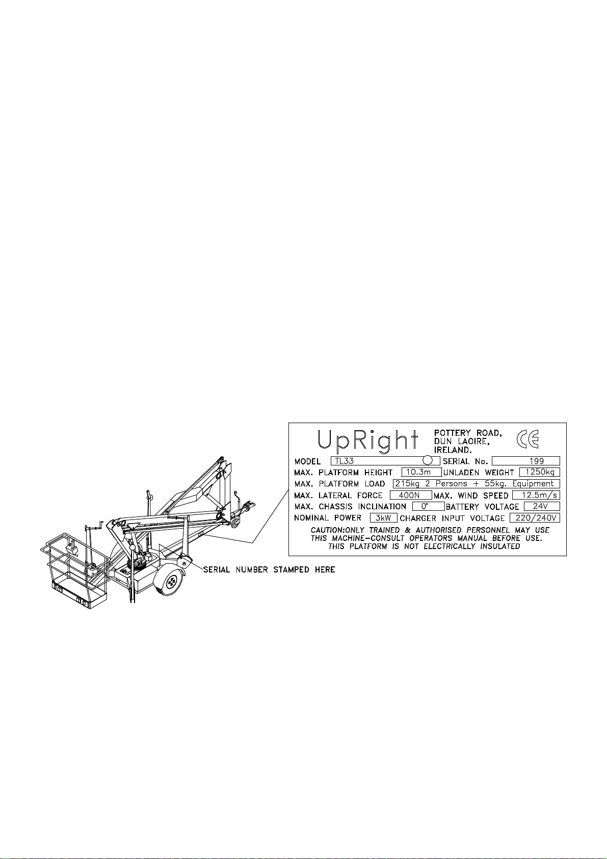
1.0 Introduction & Specifications
1.0 Introduction ................................... 1-1
Purpose.................................................. 1-1
Scope..................................................... 1-1
1.1 General Information ............................... 1-1
Description............................................. 1-1
Purpose and Limitations ......................... 1-2
1.2 Specifications ................................... 1-2
2.0 Machine Preparation
2.1 Preparation for use................................. 2-1
2.2 Preparation for shipment ........................ 2-1
2.3 Forklifting of workplatform...................... 2-2
2.4 Lifting Work Platform ............................. 2-2
2.5 Transport ................................... 2-2
2.6 Storage ................................... 2-2
Preservation........................................... 2-2
Batteries................................................. 2-2
3.0 Operation
3.0 Introduction. .................................. 3-1
General Functioning............................... 3-1
Setting up machine for use..................... 3-1
Operating the booms.............................. 3-1
Design Features.................................... .3-1
3.1 Safety Rules and Precautions............. ... 3-2
3.2 Controls and Indicators....................... ... 3-3
Platform Controls................................. .. 3-3
Lower Controls....................................... 3-4
3.3 Pre-Operation Inspection....................... 3-5
3.4 Operation ................................... 3-6
Towing ................................................ . 3-6
Deploying the outriggers......................... 3-6
Elevating platform................................ .. 3-7
Emergency Lowering ............................. 3-7
Emergency Rotation .............................. 3-8
4.0 Maintenance
4.0 Introduction .................................. 4-1
4.1 Preventative Maintenance ...................... 4-1
Preventative Maintenance Table Key ..... 4-2
Preventative Maintenance Report .......... 4-2
4.2 Battery Maintenance............................... 4-3
Battery Inspection and Cleaning.......... ... 4-3
Battery Charging.................................. .. 4-3
Battery Cell Equalization ................. ...... 4-4
4.4 Lubrication .................................. 4-5
Hydraulic Oil Reservoir and Filter........ ... 4-5
Fluid Level............................................ .4-5
Oil and Filter Replacement................... .. 4-5
4.5 Setting Hydraulic pressures.................... 4-6
Main Relief valve.................................. .4-6
Section Page
No. No.
4.6 Maintenance on Elevating Assembly.......4-6
Setting Slew Cut-Out Limit Switch...........4-7
Outrigger Limit Switches...................... ...4-8
4.7 Hydraulic Manifold ..................................4-9
Removal............................................... ..4-9
Disassembly......................................... ..4-9
Cleaning and Inspection..........................4-9
Assembly................................................4-9
Installation............................................ ..4-9
4.8 Hydraulic Pump ..................................4-11
Removal............................................... 4-11
Installation............................................ 4-11
4.9 Wheel Hubs/Bearings ..........................4-11
Maintenance & Adjustment .................. 4-11
Replacing worn bearings /
Hub Oil Seal ........................................ 4-11
4.10 Braking System ................................. 4-13
Principles of Operation..........................4-13
Adjustment of /wheel Brakes ................4-13
4.11 Hydraulic Cylinders.............................. 4-14
Upper Lift Cylinder............................... .4-14
Removal.......................................... .....4-14
Cleaning and Inspection........................4-14
Assembly..............................................4-14
Installation...................................... ......4-14
4.12 Lower Lift Cylinder ...............................4-16
Lower Lift Cylinder............................... .4-16
Removal.......................................... .....4-16
Cleaning and Inspection........................4-16
Assembly..............................................4-16
Installation...................................... ......4-16
4.13 Electric Motor ..................................4-17
Troubleshooting ..................................4-17
Disassembly................................. 4-17
Inspection ................................. 4-17
Reassembly ................................. 4-18
4.14 Adjustment of Overcentre Valves......... 4-20
5.0 Troubleshooting
5.0 Introduction ................................... 5-1
General Procedure..................................5-1
5.1 Trouble shooting charts.......................... 5-2
5.2 General information .............................. 5-4
5.3 D.C. Motor Control ................................ 5-5
5.4 Troubleshooting the MOS90 .................. 5-6
6.0 Schematics
6.0 Introduction ................................... 6-1
6.1 Electrical Schematic ...............................6-3
6.2 Hydraulic Schematic ...............................6-7
Table of Contents

II TL33 Work Platform
Contents
Section
i
Section Page
No. No.
7.0 Illustrated Parts Breakdown
7.0 Introduction .................................. .7-1
7.1 Index .................................. .7-1
7.2 Illustrated Parts ................................... 7-2
Chassis Assembly................................ 7-2
Booms and Posts Assembly................. 7-4
Cage Assembly ................................... 7-6
Axle and Brake Hub Assembly............. 7-8
Hub Assembly ..................................7-10
Brake Assembly..................................7-12
Slew Gearbox Assembly.....................7-14
Lower Control Box Assembly ..............7-16
Tailboard Assembly ............................7-18
Coupling Assembly .............................7-20
Label Kit ..................................7-22
Main Manifold Block Assembly............7-24
Lift Cylinder Assembly ........................7-26
Hydraulic Assembly ............................7-28
Pump Motor Controller Assembly........7-30
Upper Control Box Assembly ..............7-32
Electrical Assembly.............................7-34
Fig. Title Page
No.
1-1 TL33 Work Platform................................1-1
2-1 Lifting the TL33 .................................2-2
3-1 Platform Controls .................................3-3
3-2 Lower Controls .................................3-4
3-3 Releasing Outrigger Lock Pin..................3-6
3-4 Emergency Lowering Valves...................3-8
4-1 Lubrication Points .................................4-5
4-2 Oil and Filter Replacement .....................4-5
4-3 Main Manifold Block................................4-6
4-4 Supporting the Elevating Assembly.........4-6
4-5 Slew Cut-out Limit Switch .......................4-7
4-6 Outrigger Limit Switch.............................4-8
4-7 Main Manifold Block..............................4-10
4-8 Hydraulic Pump . ..............................4-11
4-9 Replacing Bearings / Oil Seal ...............4-12
4-10 Wheel Hub Assembly............................4-12
4-11 Braking Arrangement............................4-13
4-12 Replace Brake Cable ............................4-13
4-13 Upper Lift Cylinder ...............................4-15
4-14 Lower lift Cylinder ...............................4-15
4-15 Hydraulic Cylinder Components ............4-15
4-16 Electrical Test Circuit ............................4-17
4-17 Electric Motor Assembly .......................4-19
6-1 Electrical Schematic ...............................6-5
6-2 Hydraulic Schematic................................6-8
6-3 Hydraulic Manifold...................................6-8
Table Title Page
No.
1-1 Specifications .................................1-2
3-1 Platform Controls and Indicators ............3-3
3-2 Lower Controls .................................3-4
4-1 Preventative Maintenance ......................4-2
4-3 Temperature Correction for Electrolytes..4-4
5-1 Trouble Shooting .................................5-2
5-2 MOS90 Flash Faults...............................5-6
6-1 Electrical Schematic Legend............6-3, 6-4
6-2 Hydraulic Schematic Legend...................6-7
Table of Contents
(cont’d.)
List of Illustrations
List of Tables
This manual suits for next models
1
Table of contents
Other Upright Construction Equipment manuals