tropitone Basta Sole Cabana User manual

1
CABANA / PAVILION ASSEMBLY
ALUMINUM FRAME MODELS
Thank you for selecting Tropitone® Basta Sole® Cabana /
Pavilion for your shade needs.
WARNING: Do not try to lift or flip Cabanas / Pavilions with only
one person. Components may be heavy and awkward to handle,
and may result in injury to persons or damage to property if not
lifted properly.
CAUTION: When instructed to fully tighten screws, do not over
tighten and strip the threads.
Read through all steps before starting assembly.
Completely unpack all boxes and thoroughly check for
items that may be individually wrapped (finial, etc.)
Tools needed:
Medium (#2) Phillips Screwdriver
7/16” Combination Wrench
3/16” Hex Key
3/8” Power Drill
5/16” Drill Bit
Level
Safety Glasses
Parts List:
(1) Finial (decorative top)
(4) ¼-20 x 1-1/4” Flat Head
Screws
(4) Curtain Rod Brackets
(8) ¼-20 x 3” Socket Head
Screws
(8) ¼-20 x 2-1/2” Socket
Head Screws
(8) ¼-20 x 1-3/4” Socket
Head Screws
(48) ¼” Flat Washers
(24) ¼-20 Locking Nuts
(1) Upper Frame Assembly with
Top Cover
(4) Corner Bracket Assembly
(4) Curtain Rods (longer,
thinner) Sheer Double
Curtain Rods (Optional)
(4) Curtains
(8) Sheer Curtains (Optional)
(4) Center Curtain Ties
(4) Corner Poles (shorter,
thicker)
(4) Umbrella Bases (see Step 5
for various types)
Assembled cabanas
are large & heavy.
Assemble at place of
use
.
2
Step 1
CAUTION: To avoid damage to the finish of your Cabana frame,
prepare a smooth, non-scratch work surface (shipping container, a
tarp or pool towels can be used).
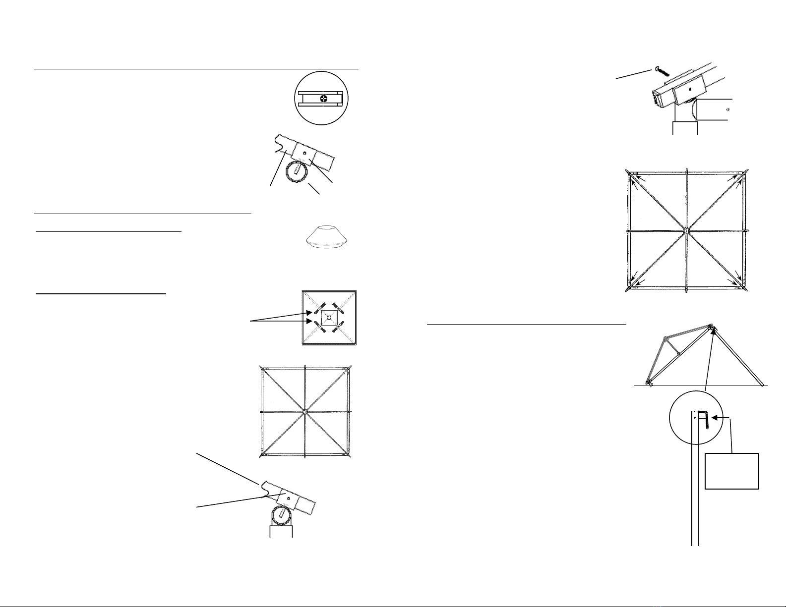
Set the (4) Corner Bracket Assemblies in a
square spaced at a distance to accept the
length of the Curtain Rods.
Connect the (4) Curtain Rods to the Corner
Bracket Assemblies in such a way that the
assembly hole for the Curtain Rod Bracket
is located at the top and outside of the
frame (shown in diagram A). This will allow
the Curtain Rod Bracket (installed in Step 2)
to receive the Arm as shown in the cutaway
diagram in the Step below. Curtain Rods
with a secondary sheer rod will require the
smaller sheer rod to be oriented to the
inside of the assembled Cabana (Optional
Sheer Curtain Rod shown in diagram B).
Note: Curtain Rods and Sheer Curtain
Rods for 12’ Cabanas are equipped with a
Valance Support located in the center of the
curtain rod.
Slide Rods fully onto the end tube of the
Corner Brackets. Install (8) ¼-20 x 2-1/2”
Socket Head Screws with (8) ¼” Flat
Washers into pre-drilled thru holes of the
Curtain Rods loosely to retain the Corner
Brackets (at 4 corners). Secure with (8) ¼”
Flat Washers and (8) ¼-20 Locking Nuts.
Do NOT fully tighten the Socket Head
Screws and Locking Nuts until Step 3.
A
B
3
Step 2
Install the (4) Curtain Rod Brackets onto the
Curtain Rods using (4) ¼-20 x 1-1/4” Flat
Head Screws. Make sure the Curtain Rod
Bracket is positioned on the Curtain Rod so
the Bracket can receive the Arm in Step 3
as shown in the cutaway diagram. Fully
tighten the screws, but do not over tighten
and strip the threads.
Step 3
On Cabana Models w/no Vent
Install the Finial (decorative top) onto the Upper
Frame Assembly (cover already installed). Fully
tighten.
On Cabana Models w/Vent
Install the Vent to the Upper Frame Assembly
and secure to arms with snaps and the
Velcro Straps. Then install the Finial onto the
Upper Frame.
With two or more persons, carefully
open the Upper Frame Assembly to
the full open position.
Place the Upper Frame Assembly onto the
Corner Brackets with the Arms in the
Bracket channels (at 4 corners).
Position the center arms into the
Curtain Rod Brackets (4 places).
Install the ¼-20 x 1-3/4” Socket Head
Screw with ¼” Flat Washer into the
Curtain Rod Brackets (4 places).
Secure with ¼” Flat Washer and ¼-20
Locking Nut. Fully tighten.
ROD
ARM
(INSTALLED AT STEP 3)
BRACKET
4
Step 3 (Continued)
Install the ¼-20 x 1-3/4” Socket Head
Screw with ¼” Flat Washer into the
Corner Bracket Assembly (at 4
corners). Secure with ¼” Flat Washer
and ¼-20 Locking Nut. Fully tighten.
Fully tighten (8) ¼-20 x 2-1/2” Screws
and ¼-20 Locking Nuts to secure the
Curtain Rods to the Corner Bracket
Assemblies (8 places).
Step 4
Using (2) persons, lift one side of the
Cabana high enough to insert (2) Corner
Poles. Install Poles with Valance Supports
facing out. (Corner Pole with Valance
Support shown in diagram at below right)
Install ¼-20 x 3” Socket Head Screws with
¼” Flat Washers into pre-drilled holes to
hold Corner Poles to Corner Bracket
Assemblies. Secure with ¼” Flat Washers
and ¼-20 Locking Nut. Fully tighten (2
places).
Valance
Support
5
Sleeve
Step 4 (Continued)
Using two persons, lift the remaining side of the
Cabana high enough to insert (2) Corner Poles.
Install Poles with Valance Supports facing out.
Install hardware to hold remaining (2) Corner
Poles to Corner Bracket Assemblies as directed
above. Fully tighten (2 places).
Pull to align Valance over Valance Supports.
WARNING: Screws and Locking Nuts must be fully tightened
to secure Poles to Corner Bracket Assemblies. Failure to do
so may cause Corner Poles to separate from Corner Bracket
Assemblies and result in injury to persons or damage to
property.
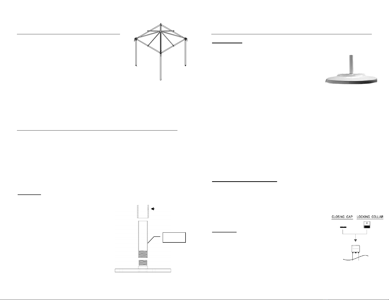
Step 5
Basta Sole® Cabanas are available with (2) Base options
(SP12R2F or CFA24R15F) or an In Ground Gopher Sleeve.
Below are assembly instructions for these models:
WARNING: Since the actual ground surface the Steel Plate Bases
or Gopher Sleeves will be installed on or in can vary substantially,
please consult a contractor or other qualified professional who can
best advise you on how to secure the Steel Plate Bases or
Gopher Sleeves to your ground surface.
SP12R2F – These weigh about 25 lbs. each and should be
bolted to the ground using 3/8” bolts (not included).
Place an assembled SP24R2F Umbrella Base at
each pole. Lift the Corner Poles onto the Base
Sleeve. Push the Base into place and align holes
in Pole and Sleeve. Align each Pole into a vertical
position. Check with a level.
Install ¼-20 x 3” Socket Head Screws and ¼”
Flat Washers to hold the Corner Poles to the
Umbrella Base. Secure with ¼” Flat Washer
and ¼-20 Locking Nut. Fully tighten the
Screws and Nuts (at 4 corners).
6
Step 5 (Continued)
CFA24R15F – These weigh about 90 lbs. each and are free-
standing (for use with Vented Cabanas only).
Place an assembled CFA24R15F Umbrella
Base at each pole. Lift the Corner Poles
onto the Base Sleeve. Push the Base into
place. Align each pole into a vertical
position. Check with a level.
Using the assembly hole in the bottom of the
Corner Pole as a guide, drill through one side of
the Base Sleeve using a Power Drill with a 5/16”
Drill Bit. Being careful not to move the Base or
Corner Pole, move to the opposite side of the
Corner Pole and repeat the drill operation to
complete the thru hole. Repeat the process for
the remaining (3) Bases.
Install ¼-20 x 3” Socket Head Screws and ¼” Flat Washers to
hold the Corner Poles to the Umbrella Base. Secure with ¼” Flat
Washer and ¼-20 Locking Nut. Fully tighten the Screws and Nuts
(at 4 corners).
In Ground Gopher Sleeve
WARNING: Since the actual ground surface the Gopher Sleeves
will be installed in can vary substantially, please consult a
contractor or other qualified professional who can best advise you
on how to secure the Gopher Sleeves to your ground surface.
Parts List
Gopher Sleeve
Locking Collar
Closing Cap

7
Step 5 (Continued)
Tools Required
(2) 1/2” Wrenches
Power Drill
21/64” Drill Bit
Large Philips Screwdriver
Safety Glasses
Hardware Required (not included)
(4) 5/16" x 4" Hex Bolt
(8) 5/16" Flat Washers
(4) 5/16" Lock Nut
Warning: When the Cabana is removed, the Locking Collars must
be removed and the Closing Caps installed to prevent trip
hazards.
8
Step 5 (Continued)
Warning: The 5/16” bolt must not stick out from the lock nut and
create a safety hazard.
INSTALL 5/16” BOLT
WITH WASHER AT HEAD
THROUGH COLLAR
SECURE WITH WASHER
AND LOCK NUT

9
Step 5 (Continued)
Step 6
Curtains are installed outside the
Poles using Loops with snaps to
secure to the Curtain Rods.
Curtain Mounting Tabs and
Bottom Ties face towards inside
of Cabana with one Tie Panel on
each side of the Corner Pole at
bottom.
To hang the Curtain, open Curtain Top
Flaps by gently releasing the snaps
and pulling apart. Install the Curtain
Top Flaps over the Curtain Rod. Close
the Flaps and engage the snaps.
Wrap the Bottom Curtain Tie (attached
to the curtain at bottom center) around
the Corner Pole and engage the
Velcro at the ends of the Bottom
Curtain Tie.
10
Step 6 (Continued)
To secure the Curtain to the center of
the Corner Pole, secure the Center
Curtain Tie to the Curtain by pressing
the (2) Snap Studs on the Center
Curtain Tie through the (2) holes in the
Curtain Mounting Tab. Engage the
snap sockets to the snap studs from
the Center Curtain Tie through the
Curtain Mounting Tab located in the
center of the curtain (Mounting Tab
shown at lower right).
Fully open the Curtains and tie back
by engaging the Velcro at the ends
of the Center Curtain Ties.
Optional Sheer Curtains are to be
hung on the optional Sheer Curtain
Rod in the same manner as the
standard Curtains but without
wrapping around the Corner Pole.
Sheer Curtain Rod
This manual suits for next models
1
Popular Tent manuals by other brands


Coleman
Coleman 2000033134 Assembly & instruction manual

Ozark Trail
Ozark Trail W784.1 Assembly instructions and owner's manual

SlingFin
SlingFin CrossBow 2 instructions

Coleman
Coleman 9600-141 instructions

Palram
Palram Arizona 5000 Wave - WINGS manual

COVERPRO
COVERPRO 56184 Owner's manual & safety instructions