B - 1 Operating manual – DA 4 / DA 4 M Flow Rate Control Unit EN
TABLE OF CONTENTS
01. General description ................B - 01
02. Read before commissioning .........B - 02
03. Commissioning ....................B - 03
04. Operation ........................B - 03
05. Decommissioning ..................B - 05
06. Care and maintenance ..............B - 05
07. Faults and error rectification .........B - 06
08. Internal view of the DA 4 ............B - 06
09. Technical data .....................B - 06
This publication replaces all previous publications. No part of this publication
may be reproduced in any form nor processed, copied or distributed by means
of electronic systems without our prior written approval. We reserve the right
to technical modifications. All rights reserved. Product names are used without
guaranteeing the free usability and are generally in accordance with the presen-
tation of the manufacturers. The product names used are registered trade names
and should be regarded as such. Changes in construction in the interest of an
ongoing product improvement as well as modifications in form and colour are
reserved. The scope of delivery may deviate from the product images. This docu-
ment was created with due diligence. We do not assume any liability for errors
or omissions. © TROTEC®
01. GENERAL DESCRIPTION
The DA 4 / DA 4 M MultiQube flow rate control unit
is a device for commercial use in order to rectify wa-
ter damage in interspace and insulation layers. It is
a mobile, noise-reduced and electronically operated
device for controlling suction air flows.
In practice, new water damage is characterised by
The flow rate control unit has been designed for
vacuum drying and, by means of the active control of
three drying zones, makes it possible to optimize and
shorten the drying phase.
The flow rate control unit has two sensors - one air
sensor for measuring the room air humidity and tem-
perature and one humidity sensor for recording the
humidity values of the insulation layers affected.
The automatic controls of the DA 4 record in se-
quence the humidity values of three different ducts by
means of the humidity sensor and then concentrate
the entire compressor performance to the duct with
the highest humidity value. After a 10-minute drying
phase, the humidity values of the individual ducts are
measured again and the most humid duct is selected
again.
In this way, the total drying time can be significantly
accelerated - between 30 and 70%, depending on the
construction concept.
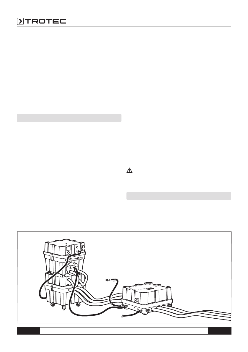
The flow rate control unit is installed between the wa-
ter extractor and the drying zones.
The air sensor of the flow rate control unit records the
room humidity and temperature. If the room humidity
exceeds values which no longer enable a drying proc-
ess, warning signals are emitted.
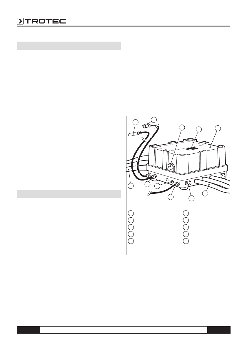
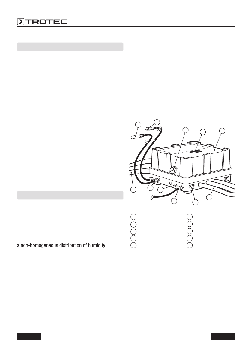
The DA 4 and DA 4 M flow rate control unit saves
230 V
9
8
3
6
6
45
7
10
2
1
1 Humidity sensor
2 Room sensor
3 Adapter for sensor
4 Display
5 Casing
6 Inputs/outputs
7 Cable winding
8 Network cable 230
9 Key
10 Sensor connections
(Fig.1: product overview)
EN Operating manual – DA 4 / DA 4 M Flow Rate Control Unit B - 2
the measurements on an integrated USB flash drive.
Previous drying processes are thus documented. The
DA 4 M flow rate control unit additionally sends the
sensor measurements to a WEB centre and thus of-
fers online remote monitoring of the drying process.
02. READ BEFORE COMMISSIONING
The DA 4 / DA 4 M flow rate control unit is to be
used as a control unit for drying insulation layers in
the suction process of floor screed or flat roofs ex-
clusively. The unit consists of a casing in which the
valves, the control unit and the connection nozzles are
installed, as well as the humidity sensor with adapter,
which is plugged into the respective holding fixture for
transportation purposes. During operation, the sensor
is installed at a four-fold distributor at the compressor
by means of the adapter.
The humidity sensor must not have direct con-
tact with water!
Never place items on the device or step on it.
The flow rate control unit can be used with all con-
ventional compressors in suction processes for the
drying of insulation layers. Furthermore, the device is
specifically aligned to the Trotec Multi-Qube modules
VE 4, WA 4,WA 4i, WA 6 and VE 6.
The task of the flow rate control unit is to efficiently
distribute the suction flow to the existing core drill
holes; it is positioned between the water extractor
and the core drill holes. Water, particulate matter, fine
dust or other small particles are not filtered through
the device. Foreign bodies of this kind do not impair
the function of the device.
Foreign bodies with a diameter of more than
15mm may lead to a clogging of the valves. For
this reason, the core drill hole is to be cleaned
thoroughly before drying. An industrial vacu-
um cleaner is suitable for cleaning.
The flow rate control unit does not have any defined
inputs and outputs. It is irrelevant from which side the
hoses are connected.
All three inputs and all three outputs must be
connected and used.
Ensure a proper connection of the inputs and outputs.
Insufficient connections with the aluminium nozzle of
the flow rate control unit may result in leakages. This
will lead to reduced drying performance. In a worst
case scenario, water leaks from the connection and
causes water damage. Use hoses with smooth and
elastic internal surfaces or spiral hoses with a cor-
responding special clamp. With the flow rate con-
trol unit, you can directly control three core drilling
holes. By means of T/Y pieces or other distributors,
the number of the controllable core drilling holes can
be expanded. Here, ensure that the core drilling holes
which are controlled via one duct are grouped closely
together.
Generally, before using the MultiQube elements, wa-
ter in the core drilling holes must be removed via suc-
tion before starting the drying process. This shortens
the drying time for rectifying the water damage.
All three ducts of the flow rate control unit must be
connected as otherwise correct functioning cannot
be guaranteed and the connected compressor turbine
will be damaged.
The use of a flow rate control unit in explosion-risk
rooms and atmospheres is inadmissible.
The flow rate control unit may only be operated by
specialist staff and experts who have been instructed
regarding the operation of the devices and are trained
in the area of insulation layer drying technologies.
The operating manual must be followed. Instructed
persons are persons who have been informed and,
if required, trained regarding the tasks transferred to
them and the possible hazards occurring in the event
of inappropriate behaviour.
Repair and maintenance work on electrical parts may
only be executed by a specialist electrician. On con-
struction sites, the DA 4 may only be connected via
an electrical 1~230V, 50Hz; 16A energy supply with a
corresponding upstream FI residual current operated
protective device (RCD) 30mA, in accordance with
with DIN VDE 100.