Trotec T510 User manual

TRT-BA-T510-TC2014-04-002-EN
T510
EN
OPERATING MANUAL
MOISTURE MEASURING
DEVICE

2 EN
moisture measuring device T510
Table of contents
Notes regarding the operating manual.................................2
Safety .....................................................................................2
Information about the device................................................3
Transport and storage...........................................................4
Operation ...............................................................................5
Table of wood types ............................................................10
Measuring principle ............................................................10
PC software..........................................................................14
Maintenance and repair ......................................................15
Errors and faults..................................................................15
Disposal ...............................................................................15
Notes regarding the operating manual
Symbols
Warning of electrical voltage
This symbol indicates dangers to the life and health of
persons due to electrical voltage.
Warning
This signal word indicates a hazard with an average
risk level which, if not avoided, can result in serious
injury or death.
Caution
This signal word indicates a hazard with a low risk
level which, if not avoided, can result in minor or
moderate injury.
Note
This signal word indicates important information (e.g.
material damage), but does not indicate hazards.
Info
Information marked with this symbol helps you to carry
out your tasks quickly and safely.
Follow the manual
Information marked with this symbol indicates that the
operating manual must be observed.
You can download the current version of the operating manual
and the EU declaration of conformity via the following link:
T510
https://hub.trotec.com/?id=44143
Safety
Read this manual carefully before starting or using the
device. Always store the manual in the immediate vicinity
of the device or its site of use.
Warning
Read all safety warnings and all instructions.
Failure to follow the warnings and instructions may
result in electric shock, fire and/or serious injury.
Save all warnings and instructions for future
reference.
This appliance can be used by children aged from
8years and above and persons with reduced physical,
sensory or mental capabilities or lack of experience
and knowledge if they have been given supervision or
instruction concerning use of the appliance in a safe
way and understand the hazards involved.
Children shall not play with the appliance. Cleaning and
user maintenance shall not be made by children
without supervision.
• Do not use the device in potentially explosive rooms or
areas and do not install it there.
• Do not use the device in aggressive atmosphere.
• Do not immerse the device in water. Do not allow liquids to
penetrate into the device.
• The device may only be used in dry surroundings and must
not be used in the rain or at a relative humidity exceeding
the operating conditions.
• Protect the device from permanent direct sunlight.
• Do not expose the device to strong vibrations.
• Do not remove any safety signs, stickers or labels from the
device. Keep all safety signs, stickers and labels in legible
condition.
• Do not open the device.
• Observe the storage and operating conditions as given in
the Technical data chapter.

EN 3
moisture measuring device T510
Intended use
Only use the device to measure the moisture content of wood
and other soft building materials (e.g.gypsum, plaster). Observe
and comply with the technical data.
To use the device for its intended use, only use accessories and
spare parts which have been approved by Trotec.
Improper use
Do not use the device in potentially explosive atmospheres, for
measurements in liquids or at live parts.
Any unauthorised changes, modifications or alterations to the
device are forbidden.
Personnel qualifications
People who use this device must:
• have read and understood the operating manual, especially
the Safety chapter.
Residual risks
Warning of electrical voltage
There is a risk of a short-circuit due to liquids
penetrating the housing!
Do not immerse the device and the accessories in
water. Make sure that no water or other liquids can
enter the housing.
Warning of electrical voltage
Work on the electrical components must only be
carried out by an authorised specialist company!
Warning
Risk of suffocation!
Do not leave the packaging lying around. Children may
use it as a dangerous toy.
Warning
The device is not a toy and does not belong in the
hands of children.
Warning
Dangers can occur at the device when it is used by
untrained people in an unprofessional or improper way!
Observe the personnel qualifications!
Caution
Keep a sufficient distance from heat sources.
Note
To prevent damages to the device, do not expose it to
extreme temperatures, extreme humidity or moisture.
Note
Do not use abrasive cleaners or solvents to clean the
device.
Information about the device
Device description
The material moisture measuring device T510 enables the
determination of the moisture content in wood and other soft
building materials (e.g. gypsum, plaster) according to the
resistance measurement method.
The device comes with two different types of measurement: for
wood moisture on the one hand and for building moisture on the
other. Different wood types or materials can be set for these
measuring modes.
The device can be operated via a capacitive touchscreen control
panel. When not in use, an automatic switch-off saves the
battery.
Optionally, different electrodes can be connected via a
separately available adapter set.
You can connect the device to a computer by using the USB
cable included in the scope of delivery. Then you can extract
and analyse your measured results with the optional
MultiMeasure Studio software.
Device depiction
4
3
1
2
5
6
No. Designation
1 Display
2 Cross control
3 Battery compartment with cover
4 Power button
5 USB interface
6 Connections for measuring tips with protective cap

4 EN
moisture measuring device T510
Cross control
7
10
9
8
11
No. Designation
7 Up button
8 Right/back button
9 Down button
10 OK button
11 Left/menu button
Display
12
18
17
16
15
14
13
No. Designation
12 CFG symbol (configuration mode display)
13 Measuring mode
14 Upper measured value indication (moisture)
15 Percentage indication
16 Lower measured value indication (temperature)
17 Temperature unit
18 Configuration mode
Technical data
Parameter Value
Model T510
Wood moisture
Measuring range 0.0 to 100.0M%
Accuracy 0 to 5M%: ±0.8M%
5 to 30M%: ±0.2M%
30 to 100M%: ±0.1 M%
Temperature
compensation
0.0 to 60.0M%
Material moisture
Measuring range 0 to 100digits
Accuracy 0.1digits
Resolution 0.1digits
Penetration depth
(coupling)
approx. 10 mm
General technical data
Measuring method resistance measuring method
Display LCD
Interface USB
Operating conditions 0°C to 50°C with <90 %RH
(non-condensing)
Storage conditions -20 to 60°C at <90%RH
(non-condensing)
Power supply 4x 1.5 V, AAbatteries
Weight approx. 280 g
Dimensions
(lengthx widthx height)
187mmx 63mmx 35mm
Scope of delivery
• 1x Device T510
• 4x 1.5V batteries, typeAA
• 1x Protective cap
• 1x Electrode tips (1.5x 20mm)
• 2x Union nut
• 1x Wood type directory
• 1 x Factory test certificate
• 1 x Quick guide
Transport and storage
Note
If you store or transport the device improperly, the
device may be damaged.
Note the information regarding transport and storage of
the device.

EN 5
moisture measuring device T510
Transport
When transporting the device, ensure dry conditions and and
protect the device from external influences e.g. by using a
suitable bag.
Storage
When the device is not being used, observe the following
storage conditions:
• dry and protected from frost and heat
• protected from dust and direct sunlight
• The storage temperature is the same as the range given in
the Technical data chapter.
• Remove the batteries from the device.
Operation
Installing the measuring tips
Mount the measuring tips included in the scope of delivery
before first use.
Note
Exclusively use the original measuring tips included in
the scope of delivery. Other measuring tips might bend
or damage the holder at the measuring device.
19
21
20
1. Remove the protective cap(21).
2. Detach the nuts(19)
3. Insert the measuring tips(20) in the nuts(19).
4. Refasten the nuts(19) on the device.
Inserting the batteries
Insert the supplied batteries before first use.
Caution
Make sure that the surface of the device is dry and the
device is switched off.
3
1. Remove the battery compartment cover(3).
2. Insert the batteries with correct polarity.
3. Insert the battery compartment cover(3).
ðThe device can now be switched on.
Switch-on
Note:
The cross control is very sensitive. Therefore, avoid dirt on the
control panel, because it could be misinterpreted by the device
as keystroke.
Before use make sure that the touchscreen control panel is dirt-
free.
If required clean the touchscreen control panel according to
chapter Cleaning the device.
1. Press the On/Off button(4) until a beep is emitted.
ðThe device performs a short self-test.
ðThe device name and firmware version is shown on the
display.
ðThe battery charge is indicated on the display.
ðThe device is ready for operation.
ðThe displayed units are based on the settings of the last
utilization.
Note:
Note that moving from a cold area to a warm area can lead to
condensation forming on the device's circuit board. This
physical and unavoidable effect can falsify the measurement. In
this case, the display shows either no measured values or they
are incorrect. Wait a few minutes until the device has become
adjusted to the changed conditions before carrying out a
measurement.

6 EN
moisture measuring device T510
Performing the wood moisture measurement
Warning
When handling the device there is a risk of injury due
to the exposed measuring tips. Always put on the
protective cap when not in use.
Note
Never force the measuring device into the material to
be measured or yank it out. Applying force can lead to
bending or breaking of the measuring tips.
üThe device is switched on.
üThe wood temperature is set.
üThe wood type is set.
1. Choose a suitable measuring position. The measurement is
not to be performed at places with visible deficiencies (e.g.
cracks, resin pockets, branches).
Further observe the following:
– a = 30cm
– c = insertion depth
– d = thickness
2. Insert the measuring tips transverse to the fibre direction
with a 30cm distance to one of the two ends of the sawn
timber.
– If the material to be measured is shorter than 60cm, the
measuring position is in the centre.
3. If possible, prick the measuring tips a few millimetres into
the material.
4. Read the measured value from the upper measurement
value display.
5. Carefully pull the device out of the material by gently
moving it in turns to the left and to the right.
Performing the building moisture measurement
Warning
When handling the device there is a risk of injury due
to the exposed measuring tips. Always put on the
protective cap when not in use.
Note
Never force the measuring device into the material to
be measured or yank it out. Applying force can lead to
bending or breaking of the measuring tips.
üThe device is switched on.
üThe measurement type for building moisture is set.
1. If possible, prick the measuring tips a few millimetres into
the material.
2. Read the measured value from the lower measurement
value display.
– For measured values of less than 15digits the display
reads: ----.
– For measured values above 100digits the display
flashes.
3. Carefully pull the device out of the material by gently
moving it in turns to the left and to the right.
Key lock
1. Briefly press the On/Off key(4) during operation.
ðThe device emits a short beep.
ðLoC on is indicated on the display.
ðKey lock is activated.
2. Press the On/Off key(4) again.
ðThe device emits a short beep.
ðLoC oFF is indicated on the display.
ðKey lock is no longer activated.

EN 7
moisture measuring device T510
Configuration mode
1. Press the Left/menu key(11) for approx. 2seconds.
ðThe device emits a short beep.
ðThe CFG symbol(12) is displayed in the upper right
corner.
2. Use the buttons on the cross control(2) to select the
desired option.
Please note that some of the settings can only be selected with
a certain measuring mode.
12
18
14
16
Configuration
mode
Description
Lamp Setting brightness.
Available are values between 20 and 100%
and AL.on.
Switch-off after 30min unless with setting
AL.on.
SENS Selecting the sensor mode, available settings
are Wood and Build.
MAT Only available in sensor mode Wood.
Selection of different wood types, see table of
wood types.
TEMP Only available in sensor mode Wood.
Setting the value for wood temperature (fixed
value only, no measurement, value range
between -20 and +60°C).
Alarm Setting the alarm value.
value range: 0 to 100digits or M%
CAL Setting the offset value.
Will be added to the measured value.
value range for the wood moisture
measurement: -50 to +50M%
value range for the building moisture
measurement: -50 to +50 digits
Setting the type of measurement
Here you can determine whether you want to measure wood or
building moisture. You can choose from the settings Wood 120
and Build 100.
1. Select SENS whilst in configuration mode(18).
2. Press the OK button(10) for approx. 2seconds to confirm.
ðThe upper and lower measured value displays are
flashing.
3. Use the Up or Down key(9) to select the measurement
type.
4. Press the OK button(10) for approx. 2 seconds.
ðThe type of measurement was set based on your
choice.
ðThe device switches to measuring mode.
Note:
How the measured values are indicated, changes depending on
the type of measurement.
• Wood moisture:
– Upper measurement value display: measured material
moisture in %.
– Lower measurement value display: preset material
temperature in °C or °F.
• Building moisture:
– Upper measurement value display: no indication.
– Lower measurement value display: measured material
moisture in digits.
Setting the alarm limit value
Here you can determine the limit value for the alarm function.
Upon exceeding this value, the device emits an acoustic signal
and the indication ALARM flashes in the configuration
mode(18). The alarm function draws on the current measured
value.
The limit value can be determined within a range of 0 to 100.
1. Select ALARM whilst in configuration mode(18).
2. Press the OK button(10) to confirm.
ðThe upper measurement value display(14) flashes.
3. Press the Up(7) or Down(9) button to activate or
deactivate the alarm.
ðOn or Off will be indicated in the upper measurement
value display(14).
4. Press the Right/back button (8).
ðDepending on the selection, the alarm is either activated
or deactivated.
ðThe lower measurement value display(16) flashes.
5. Press the buttons Right/back(8) or Left/menu(11) to select
a digit.
ðThe selected digit flashes.
6. Press the Up(7) or Down(9) button to change the value of
the selected digit.
7. Repeat the steps 5. and 6. until the value is set as desired.
8. Press the OK button(10) for approx. 2 seconds.
ðThe alarm was set based on your choice.

8 EN
moisture measuring device T510
ðThe device switches to measuring mode.
ðWith activated alarm function the indicationALARM
continues to be displayed in the configuration
mode(18).
Adjusting the display illumination
The display illumination can be adjusted within a range of20
to100%. Another available setting is AL.on (always on). AL.on
features a brightness of 100 % and deactivates the automatic
switch-off function.
1. Select the lamp(18) whilst in configuration mode.
2. Press the OK button(10) to confirm.
3. Select the desired value by use of the Up(7) or Down(9)
button.
4. Press the OK button(10) for approx. 2 seconds.
ðThe set value will be adopted.
ðThe device switches to measuring mode.
Material settings
Note
Please note that this function can only be selected for
wood moisture measuring.
1. Select MAT whilst in configuration mode(18).
2. Press the OK button(10) for approx. 2 seconds.
ðCode will be indicated in the upper measurement value
display.
ðThe current material code (see chapter Table of wood
types) is indicated in the lower measurement value
display.
3. Press the keys Right/back(8) or Left/menu(11) to select a
digit.
ðThe selected digit flashes.
4. Press the Up(7) or Down(9) key to change the value of the
selected digit.
5. Repeat the steps 3. and 4. until the value is set as desired.
6. Press the OK button(10) for approx. 2 seconds.
ðThe desired material is set.
ðThe device switches to measuring mode.
Setting the wood temperature
Note
Please note that this function can only be selected for
wood moisture measuring.
Via this function you can determine the wood temperature in
degrees Celsius(°C) or Fahrenheit(°F). The wood temperature
is required by the device in order to determine the exact
material moisture.
Note
Determine the wood temperature prior to the
measurement, e.g. using a pyrometer.
1. Select TEMP whilst in configuration mode(18).
2. Press the OK button(10) for approx. 2 seconds.
ðThe currently set wood temperature is indicated in the
lower measurement value display.
3. Use the buttons Left or Right to select a digit.
ðThe selected digit flashes.
4. Press the Up(7) or Down(9) key to change the value of the
selected digit.
5. Repeat the steps 3. and 4. until the value is set as desired.
6. Press the OK button(10) for approx. 2 seconds.
ðThe wood temperature is set.
ðThe device switches to measuring mode.
Setting the offset
By use of CAL a single-point calibration can be carried out for
the selected sensor indications. All sensors are already factory-
calibrated and have a corresponding characteristic calibration
curve. By stating a calibration value (offset) a global shift of the
calibration curve, which has an effect on the entire measuring
range, is performed for the single-point calibration! The offset
value to be entered is that value by which the calibration curve
will be shifted.
Example:
The displayed value is always "5" too high => change the offset
value for this measurement channel to "-5".
The offset value's default setting is 0.0.
Note
Please note that changing the offset value brings about
an automatic reset of the measured values.
1. Select CAL whilst in configuration mode(18).
2. Press the OK button(10).
3. Use the buttons Left or Right to select a digit.
ðThe selected digit flashes.
4. Press the Up(7) or Down(9) button to change the value of
the selected digit.
5. Repeat the steps 3. and 4. until the value is set as desired.
6. Press the OK button(10) for approx. 2 seconds.
ðThe offset is set.
ðThe device switches to measuring mode.
ðWith set offset value the indication CAL continues to be
displayed whilst in configuration mode(18).

EN 9
moisture measuring device T510
Exiting configuration mode
Configuration mode will automatically be terminated after 8
seconds without entry.
You can quit configuration mode yourself anytime. Please note
that in such an event no changes made to the settings will be
adopted.
1. Press the Right/back key(8) for approx. 2 seconds.
ðConfiguration mode will be terminated.
Measuring mode
1. Press the keys Right/back(8) or Left/menu(11) until the
desired measuring mode is displayed.
2. The selected measuring mode(13) will be indicated on the
display(1)
13
The device comes with the following measuring modes:
Measuring
mode
Description
ACT Measured value in real time
AVG Average value of measurements since switch-
on
Min Minimum measured value
Max Maximum measured value
HOLD Measured value will be held
Holding the measured value
1. Set the measuring mode to HOLD.
ðThe current measured value will be held and displayed.
ðThe device will hold this value until the measured values
are set back or the device is switched off.
Resetting the measured values
1. Press the OK button(10) for approx. 2 seconds.
ðAll previously stored measured values of the measuring
modes AVG, MIN, MAX and HOLD will be set back.
ðAll previously stored measured values of the measuring
modes AVG, MIN, MAX and HOLD will be set back.
Measured value storage
Please note that measured values cannot be saved on the
device itself. In order to save measured values, the device has
to be connected to a PC via a USB cable using the MultiMeasure
Studio software.
1. Briefly press the OK button(10).
ðThe displayed measured value will be saved in the
software.
Further information can be gathered from the help text of the
MultiMeasure Studio software.
Temperature display configuration
Note
Please note that this function can only be selected for
wood moisture measuring.
1. Press the Up key(7) to switch between °C and °F.
ðThe temperature will be displayed in the selected unit.
ðThe unit(15) will be indicated on the display(1).
USB interface
The device can be connected to a PC via the USB interface(5).
See chapter PC software.
Switch-off
1. Press and hold the On/Off button(4) for approx.3seconds
until a beep is emitted.
ðThe device is switched off.
Connecting external electrodes
An adapter set and adapter cable are required to connect
external electrodes. For further information please contact the
TROTEC® customer service.
Connecting adapter set and adapter cable
22
25
23
24
1. Detach the nuts and remove the measuring tips, if
applicable.
2. Screw the two adapters(22) onto the device.
3. Plug the two cable ends(25) of the adapter cable(23) into
the adapters(22).
ðYou can now connect external electrodes (example:
(24)) to the device.
ðObserve the condition of the external electrodes and
prepare these for the measurement, if required.
ðFor further information on suitable electrodes please
contact the TROTEC® customer service.

10 EN
moisture measuring device T510
Table of wood types
The tables of wood types included in the scope of delivery contains
approx.200types of wood with their corresponding material codes.
The following tables contains all the material codes stored within the
device incl. typical examples of wood types:
Material code
H-
Wood type
examples
1 pine; pitch pine, control code
2 Cembra pine
3 Meranti, dark red
4poplar, silver, white poplar
5 birch, yellow, silver, sweet/black; wood fibre insulating
boards; cherry
6 spruce, Norway
7 chipboard urea; wenge
8 maple (sycamore), Scottish maple, acer, sugar maple;
acacia; yew; alder; ash; spruce Central Europe; chestnut,
sweet, buckeye; mahogany sapele, Philippines; Meranti,
light red; walnut; plum; pine, red; robinia, locust; elm;
Kauramin chipboard; cypress
9 larch; limba
10 Gaboon; mahogany, genuine, big-leaf, Okoumé; walnut,
American black; Padauk; plane
11 woodfibre hardboard; lime, basswood
12 Douglas fir; oak, red oak, northern red, English oak,
durmast oak; Oregon pine
13 rosewood, shisham
14 beech, common
15 pear; beech, common hornbeam, European; oak, white
oak, Arizona; buckeye, American chestnut; mecrussé
(Lebombo ironwood); olive; chipboard isocyanate; teak
16 mahogany Gaboon
17 Nargusta
18 bamboo light
19 red ironwood
20 oak, holm oak
21 ash, American ash
22 cocus wood (granadillo)
23 bamboo dark, melamine-faced chipboard
24 doussie (Afzelia)
25 iroko (African teak); kambala
26 ebony, African, black
27 cork; chipboard phenolic resin
28 (see table of wood types printed version)
29 (see table of wood types printed version)
30 (see table of wood types printed version)
31 (see table of wood types printed version)
32 (see table of wood types printed version)
33 (see table of wood types printed version)
34 (see table of wood types printed version)
35 (see table of wood types printed version)
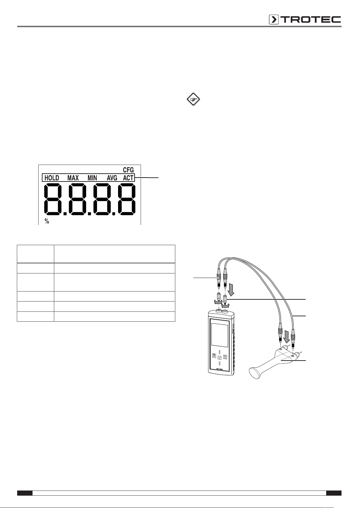
Measuring principle
During moisture measurement according to the resistance
principle an electric measuring current is generated within the
measuring device, which is conducted through the material to
be measured by means of electrodes.
With an increasing water content of the measured material to be
examined the resistance drops and conductivity builds up.
If the material to be measured has a high resistance, the
moisture content is low.
If the material to be measured has a low resistance, the
moisture content is high.
Thus, moisture measurement according to the resistance
principle is an indirect measurement method, since the humidity
is deduced from the conductivity of the measured material.
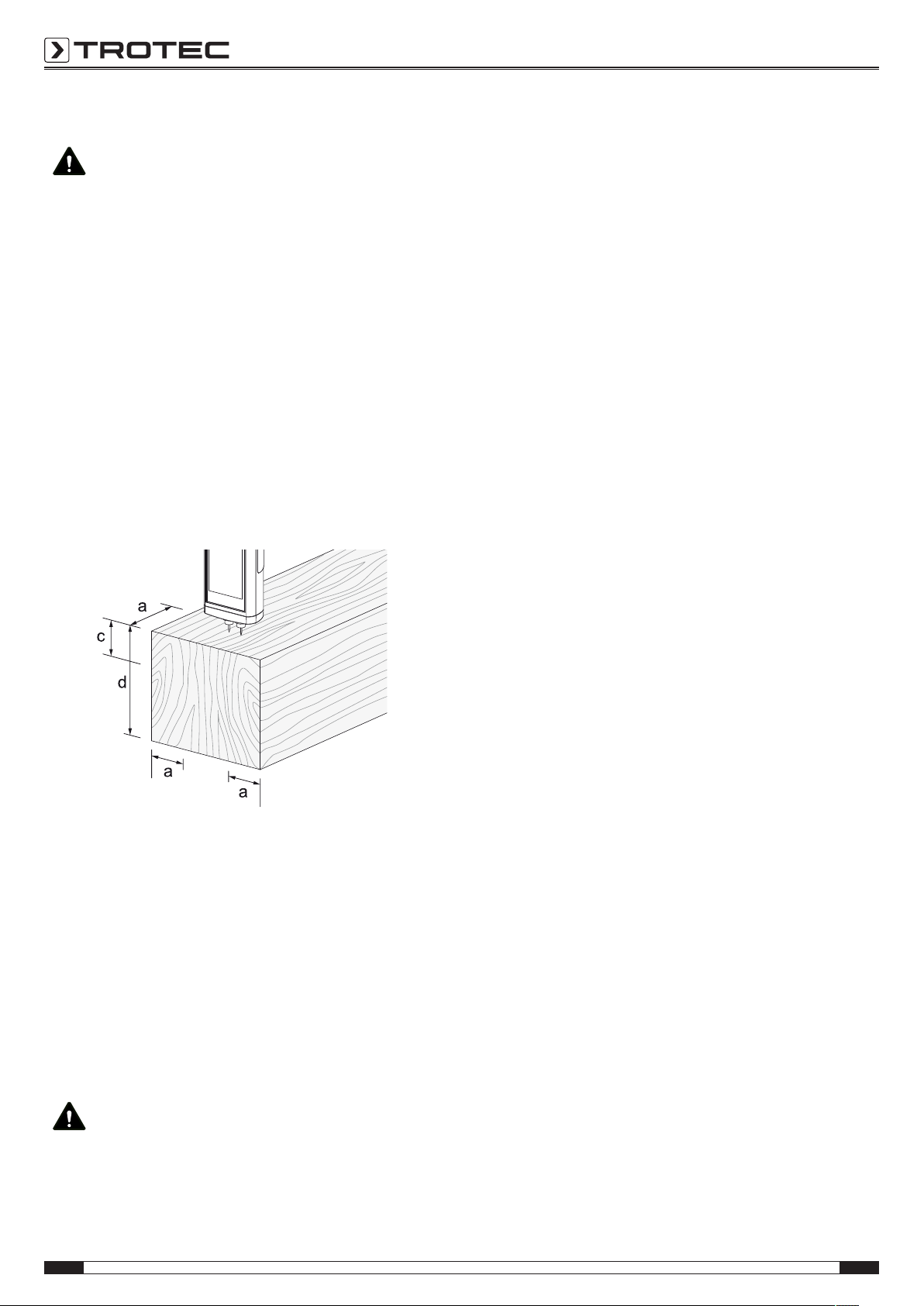
Wood moisture measurement
Every type of wood has a distinct conductivity. In order to take
this fact into consideration for the measurement, every wood
type comes with a material code that can be set.
The wood's conductivity is further influenced by the wood
temperature. In order to take this fact into consideration for the
measurement, the wood temperature can also be determined.
The wood temperature is to be determined before moisture
measurement and set accordingly.
The measuring device comes equipped with an internal
temperature compensation. The resistance curves of the
selected wood type are automatically adapted depending on the
set wood temperature.
Error sources
During resistance measurement the accuracy of the
measurement method needs to be examined. Two fundamental
types of error sources become apparent within the measuring
range from 0 to 100M%.
• There is one error stemming from the measuring principle
of the resistance measurement. This is particularly
noticeable in case of high resistance values (low
conductivity at less than 5M%). Due to the low measuring
currents the measurement value display is i.a. increasingly
falsified by molecular attraction. Listed below are the
principle-related measurement errors:
Measured value Error
0 - 5 M% 0.8 M%
6 - 30 M% 0.2 M%
31 - 100 M% 0.1 M%

EN 11
moisture measuring device T510
• The other typical error source to be considered is material
characteristics. This is particularly noticeable in case of
high moisture contents above the fibre saturation point
(high conductivity above 30 M%). Owing to the irregular
cellular structure of various wood types and the i.a.
resulting irregular water retention within and outside of the
cells, these measured values in part substantially deviate
from the actual moisture contents. It is, however, not
possible to put a precise number on these deviations, even
though the principle-related accuracies with 0.1M%
suggest a higher accuracy than for the medium measuring
range from 6 to 30M%.
When looking at both error sources, one can conclude, that the
resistance measurement method is particularly well suited for
the determination of the moisture content between 6 and 30M
%.
Notes regarding the wood moisture measurement
• Make sure you have set the correct type of measurement
(wood).
• Make sure that the correct material code was selected.
• Prior to the actual measurement process, check the
temperature conditions. To do so, for instance a pyrometer
is to be used for measuring the surface temperature of the
wood type, which should then be compared with the wood
temperature set in the device. If both temperatures are
identical, measuring can be started.
If the wood temperature is higher than the value set in the
measuring device, a higher wood moisture than really
there will be displayed as a result.
• When measuring sawn timber, observe the instructions of
DIN EN 13183-2.
• Always insert the measuring tips transverse to the wood
fibre direction.
The conductivity transverse to the wood fibre direction is
lower than that in line with it.
Depending on the type of wood it varies by the factor 2.3
to 8.
• When selecting the measuring positions observe the
following:
– Always measure the material moisture at three different
positions in order to achieve a sufficient accuracy by
means of the arithmetic average.
– Do not measure the face, because there are mainly dry
areas.
– Preferably do not measure at cracks, branches or resin
pockets either.
• Oily and/or aqueous timber preservatives affect the
measurement result.
• If possible, do not measure wood with a temperature
below -5°C. Too low wood temperatures distort the result
of the measurement.
• Avoid static charge of the material to be measured due to
friction. Static charge distorts the measurement result.
• With a wood moisture of less than 10%, electrostatic
forces can appear at the good to be measured. This can
falsify the result of the measurement. Experience has
shown that this occurs at the outlet of veneer drying
plants. Remove the static charge by use of suitable
grounding measures.
• The temperature value set within the device must be
identical to the wood temperature.
Example:
With a set temperature value of 20°C and a wood
temperature of 30°C the measurement result would be
distorted upwards by approx. 1.5%.
• The measurement's accuracy depends on the contact
pressure of the measuring tips. The measuring tips must
be connected to the wood in a way that the contact
resistance is small as compared to the measuring
resistance.
• The measurement results ought to be checked on a
sample basis by means of the Darr test.
Building moisture measurement
The electric conductivity of a dry, mineral construction material
(e.g. cementitious screed) is very low. When the building
material absorbs water, the conductivity of the material can
quickly increase or the resistance decrease.
What needs to be considered for the assessment of the
measurement results is that the results are affected by the
material composition of the measured goods:
• The presence of soluble salts can distort the measurement
result substantially.
The more salt is present, the higher will be the displayed
measurement value.
• Yet another variable for the evaluation of the results is the
connection of the electrodes with the construction
material. In case of mineral, porous building materials,
slight electrode contact can cause a comparatively high
contact resistance. This can falsify the result of the
measurement.
The accuracy of the measurement results is thus lower for
mineral construction materials than for wood.
Building moisture measurements allow only qualitative
conclusions about the moisture (dry, damp, wet).
Quantitative conclusions about the moisture content of the
mineral material to be measured can only be drawn by applying
the Darr procedure or the CM method.

12 EN
moisture measuring device T510
Notes regarding the building moisture measurement
• Make sure you have set the correct type of measurement
(build).
• For measuring, the temperature of the building material
ought to be in the range of 20°C.
• Observe disruptive influences due to electrically
conducting salts in the material:
Building-related moisture issues often occur in liaison with
water-soluble salts. Salts further the conductivity of
construction materials. During the measurement, the
building material has a lower resistance value.
Consequently, a too high measured value will be displayed.
• Observe disruptive influences due to electrically
conducting substances:
If a construction material contains electrically conducting
substances, it also has a lower resistance value, which
then simulates high moisture values. Consequently, a too
high measured value will be displayed.
From visual inspection it is usually not apparent, whether
there are any electrically conducting substances inside the
construction material. Some of the main error sources here
are in particular reinforcements, metal laminations and
conducting insulation such as slag in timber beam ceiling
constructions. Especially in case of insulation materials
with metal lamination, measured values are often
misinterpreted during the resistance measurement.
Measured value assessment building moisture
measurement
For the measured value assessment of building material, the
measurement results of the resistance measuring method can
only be used as reference for a rough orientation.
Conclusions with respect to absolute humidity in mass % (M%)
can only be drawn for measurements, performed with the exact
same marginal conditions and compositions of the building
material as indicated for the test set-up in the chart below.
This graph was created in collaboration with the Institute of
Building Materials Research of the RWTH Aachen (IBAC) and
illustrates the correlation between the measured value and the
mass-related moisture content of the examined building
materials. The presentation of the metrological results in this
form now permits a proper comparison of the measured value
and the actual moisture content. The list is limited to the most
commonly used mineral building materials. The measured
values relate to a reference temperature of 23 °C.
Key
a Moisture content (M%)
b Measured value (digits)
C 30/37 concrete (conversion not possible)
Cementitious screed (conversion: CM% = M% -1.5 to 2)
Cementitious floating screed (conversion not possible)
Anhydrite floating screed (conversion: M% = CM%)

EN 13
moisture measuring device T510
Plaster
The determination of the moisture content of plaster calls for
separate examination. As can be seen from the following chart,
the volume-based moisture content of plaster changes little at
air humidity values between 0 and 0.8(80%). However, when
exceeding the level of 0,8 (80%), the moisture content
skyrockets.
Sorption isotherm of plaster:
a
b
Key
a Relative humidity ψ
b Water content uV in %
This was also confirmed by the calibration measurements of the
Institute of Building Materials Research (IBAC). Therefore, one
can conclude, that a direct correlation between measured value
and mass-related moisture content is not possible. As sufficient
criterion for the classification of the measured values it can
however be stated, that plaster can be considered dry, when the
measured resistance value is smaller than 30 digits. When
evaluating the measured values it is imperative to observe that
different marginal conditions prevail for every measurement.
Important variables influencing the worth of the measured value
are the connection of the electrodes to the material to be
measured, the material temperature, the construction material's
composition, salt loading and aggregates.
For construction materials not listed, usually sufficient
conclusions can be drawn owing to local reference values. As a
consequence, the affected damp area can be narrowed down to
such an extent that a comparative measurement is carried out
at an evidently dry wall or floor area as basis of valuation.
By use of the higher measured values of the area to be
assessed, the spreading of the damp area can well be
determined.
Reference values for the assessment of areas damaged by
water
In case of water damage a resistance measurement can be
carried out to enable an evaluation of the area to be dried.
Based on the factual moisture content and the changeable
marginal conditions, the following table can be used to assess
the necessity for drying by use of technical means.
Here, one has to observe that the measurement results
constitute only one component of a comprehensive damage
diagnosis. The experience of the evaluator and local
circumstances play just as vital a role as the documentation of
the measurement results. The documentation further allows to
demonstrate the success of a technical drying procedure.
Digit scale values * ** ***
Insulation layers / packed bed
polystyrene (particle foam) < 36 36 to 50 > 50
polystyrene hard foam (extruded) < 36 36 to 50 > 50
polyurethane hard foam < 36 36 to 50 > 50
glass fibre < 36 36 to 45 > 45
rock wool or slag wool < 36 36 to 45 > 45
silicate foam glass < 36 36 to 50 > 50
cork, expanded volcanic rock < 31 31 to 40 > 40
wood-wool slabs < 41 41 to 50 > 50
clay fill < 41 41 to 55 > 55
coir < 36 36 to 40 > 40
Building materials
Anhydrite screed < 36 36 to 50 > 50
Cement screed < 36 36 to 50 > 50
wood cement screed < 36 36 to 50 > 50
xylolith < 41 41 to 55 > 55
Plaster < 31 31 to 40 > 40
*dry – no drying required
** threshold – drying may be required after evaluation of
the damage characteristics
*** thorough moisture penetration – drying by use of
technical means required
All values are approximations and without warranty.

14 EN
moisture measuring device T510
PC software
Use the MultiMeasure Studio Standard PC software (free
standard version) or MultiMeasure Studio Professional (paid
professional version, dongle required) to carry out a detailed
analysis and visualisation of your measured results. You can
only use all configuration, visualisation and functional options of
the device when using this PC software and a TROTEC® USB
dongle (professional).
Installation requirements
Ensure that the following minimum requirements for installing
the MultiMeasure Studio Standard or MultiMeasure Studio
Professional PC software are fulfilled:
• Supported operating systems (32 or 64bit version):
– Windows XP from service pack 3
– Windows Vista
– Windows 7
– Windows 8
– Windows 10
• Software requirements:
– Microsoft Excel (to display stored Excel files)
– Microsoft .NET Framework 3.5SP1 (is automatically
installed during software installation, where applicable)
• Hardware requirements:
– Processor speed: 1.0GHz, minimum
– USB connection
– Internet connection
– 512MB RAM, minimum
1GB hard disk space, minimum
optional: TROTEC® USB dongle (Professional) for using the
professional version of the PC software
Installing the PC software
1. Download the current PC software from the Internet. To do
so, visit the website www.trotec.de. First click on products
and services, then on services and downloads. Then select
Software in the category menu. Select the MultiMeasure
Studio Standard software from the list. If you want to use
the optionally available professional version of the PC
software "MultiMeasure Studio Professional" (dongle),
then get in touch with your TROTEC® customer service.
2. Double-click on the downloaded file to start the
installation.
3. Follow the instructions of the installation wizard.
Starting the PC software
1. Connect the device to your PC via the USB connection
cable provided in the scope of delivery.
Note
Step 2 only needs to be performed, when using the
Professional software functions.
If you only use the Standard software functions, please
proceed to step 3.
2. In order to enable the Professional functions, connect the
TROTEC® USB dongle to a free USB port on your PC.
The TROTEC® USB dongle (Professional) is automatically
detected by the operating system.
If you only connect the TROTEC® USB dongle (Professional)
to your PC after starting the PC software, click the
"Parameters" menu item in the PC software. Afterwards,
click the USB symbol (dongle check) to read the connected
TROTEC® USB dongle (Professional).
3. Switch the device on (see chapter Switch-on and
measurements).
4. Start the MultiMeasure Studio software. Depending on the
activation process you will be asked to insert the access
code that has been previously assigned to you. Only then
the dongle for releasing the according Professional tools of
the software will be activated.
Note
Information regarding the use of the MultiMeasure
Studio software is provided in the help text of the
software.

EN 15
moisture measuring device T510
Maintenance and repair
Battery change
Change the batteries when the message Batt lo is displayed
upon switch-on or the device can no longer be switched on.
See chapter Operation Inserting the batteries.
Exchanging measuring tips
Exchange the measuring tips when these exhibit signs of wear
(e.g. oxidation, heavy contamination). See chapter Operation,
Installing the measuring tips.
Note:
The device's measuring tips are bordered by use of special cap
nuts and screwed in place. A slight clearance within the nuts is
intended. To avoid peak load, it is possible that the tips loosen
somewhat after a few measurements. Hence, regularly check
the cap nuts for tight fit and, if required, retighten them by
hand. In order to avoid damage to the threads, please do not
use any tools such as pliers when doing so.
Cleaning
Clean the device with a soft, damp and lint-free cloth. Make
sure that no moisture enters the housing. Do not use any
sprays, solvents, alcohol-based cleaning agents or abrasive
cleaners, but only clean water to moisten the cloth.
Repair
Do not modify the device or install any spare parts. For repairs
or device testing, contact the manufacturer.
Errors and faults
The device has been checked for proper functioning several
times during production. If malfunctions occur nonetheless,
check the device according to the following list.
The device does not switch on:
• Check the charging status of the batteries. Change the
batteries when the message Batt lo is displayed upon
switch-on.
• Check that the batteries are properly positioned. Check the
polarity is correct.
• Never carry out an electrical check yourself; instead,
contact your TROTEC® customer service.
Disposal
The icon with the crossed-out waste bin on waste
electrical or electronic equipment stipulates that this equipment
must not be disposed of with the household waste at the end of
its life. You will find collection points for free return of waste
electrical and electronic equipment in your vicinity. The
addresses can be obtained from your municipality or local
administration. For further return options provided by us please
refer to our website https://de.trotec.com/shop/.
The separate collection of waste electrical and electronic
equipment aims to enable the re-use, recycling and other forms
of recovery of waste equipment as well as to prevent negative
effects for the environment and human health caused by the
disposal of hazardous substances potentially contained in the
equipment.
In the European Union, batteries and accumulators must not be
treated as domestic waste, but must be disposed of
professionally in accordance with Directive 2006/66/EC of the
European Parliament and of the Council of 6September 2006
on batteries and accumulators. Please dispose of batteries and
accumulators according to the relevant legal requirements.

Trotec GmbH
Grebbener Str. 7
D-52525 Heinsberg
+49 2452 962-400
+49 2452 962-200
www.trotec.com
Other manuals for T510
1
Table of contents
Other Trotec Measuring Instrument manuals

Trotec
Trotec BE49 User manual

Trotec
Trotec BD 7A User manual

Trotec
Trotec BE42 User manual

Trotec
Trotec BG20 User manual

Trotec
Trotec BF06 User manual

Trotec
Trotec BM22WP User manual

Trotec
Trotec VSC3008 User manual

Trotec
Trotec PD200 User manual

Trotec
Trotec MD200 User manual

Trotec
Trotec BM31WP User manual
Popular Measuring Instrument manuals by other brands

Leica
Leica 3D Disto user manual

General
General DM8252 user manual

Levitronix
Levitronix LEVIFLOW LFS-SU user manual

Elster
Elster REX2 installation instructions

Stanford Research Systems
Stanford Research Systems RGA100 Operating manual and programming reference

Dräger
Dräger Interlock 5000 installation instructions