Wohler A 500 User manual

A
500
Combustion and Emissions Analyzer
Contents
1. Introduction
2. Getting Started
3. Operating the A 500
4. Other Operations
...................
22
5. Setup Screen Controls
........
28
6. Maintenance
.........................
32
35
40
................
42
..........................................
43
A. Appendix A - Peltier Cooler
......
44
The Measure of Technology
30.10
.2006 part nr. 21947
Contents
1. Introduction
...............................
2. Getting Started
.........................
8
3. Operating the A 500
.............
12
22
7. Sensor Replacement
.................
35
.......................
40
9. Sales/Service Centers
................
10. Warranty
..........................................
A. Appendix A - Peltier Cooler
...............................
2
.........................
8
7. Sensor Replacement
8. Parts and Service
.......................
9. Sales/Service Centers

A 500
2 Technical Service Hotline: 978-750-9876
1. Introduction
The A 500 is a full feature residential, commercial, and light industrial grade analyzer,
that is an ideal tool for the service technician who needs to determine combustion
efficiency, carbon monoxide (CO) safety, and compliance with emissions requirements.
The A 500 utilizes an operator friendly, touch-screen display to access all its functions
and to view up to 11, easy to read, different measurements and calculations at one
time.
The A 500 measures flue gas O
2,
CO, NO, NO
2
, SO
2
, stack and ambient temperature,
pressure and draft. The A 500 also calculates and displays combustion efficiency,
stack loss, excess air, CO
2
, NO
x
, and dew point temperature. Additionally the A 500
also calculates CO, NO, NO2, NO
x
and SO
2
, to an O
2
reference selected by the user.
The A 500 comes standard with data storage for 850 complete combustion records
and, with 2 way IRDA communication capabilities, the built-in IR port can transmit test
information to a printer or PC for record keeping with just a touch of the screen. The
operator can also upload customer information from their PC to the A 500 via the IRDA
interface or can quickly and easily enter new customer information directly into the
units memory using the alphanumeric keyboard feature of the touch-screen.
Information on all models of the A 500 is contained in this manual so please disregard
information that does not relate to your model.
1.1 The A 500 Features:
1. Introduction
Figure 1: A 500

A 500
3
1. Introduction
• Measures and displays: O
2
and CO content in the flue-gas, combustion-air tempe-
rature, stack temperature, and pressure / draft.
• Calculates and displays: CO
2
content in the flue gas, combustion efficiency, excess
air, stack loss, and
flue gas dew point.
• Measures and displays: NO, NO
2
, SO
2
, and CO
HIGH
(depending on model)
• Displays emission measurements for NO, NO
2
, and/or SO
2
.
• Emission conversions can be displayed in parts per million (ppm), milligrams of
pollutant per cubic meter of gas (mg/m
3
), pounds of pollutant per giga BTU (#/
GBTU), or grams of pollutant per gigajoule (g/GJ).
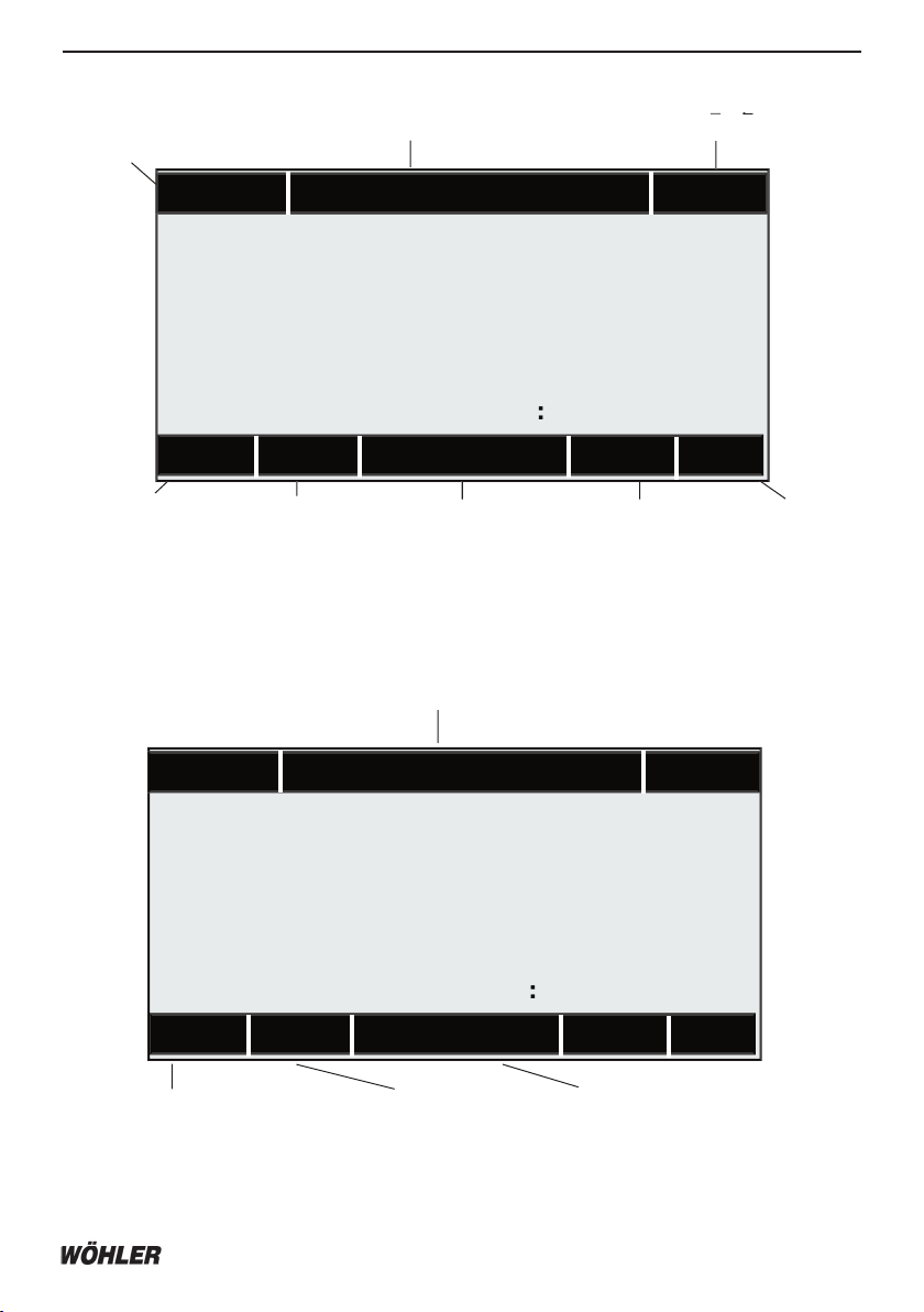
• All combustion calculations and measurements are displayed on one screen with
emission measurements and calculations on a second.
• Real-time, on-screen, graphical display of any measured or calculated test values.
• CO sensor has a warning indicator manual bypass to protect the sensor from high
concentrations of carbon monoxide.
• Displays temperature in either °C or °F and pressure in either inches of water co-
lumn (in H
2
O), or millibars (mbar).
• When unit is turned on it automatically zeros and purges all sensing channels with
ambient air for 60 seconds .
• The water trap and filters are conveniently located at the top of the analyzer for
easy viewing, draining or changing.
• The A
500
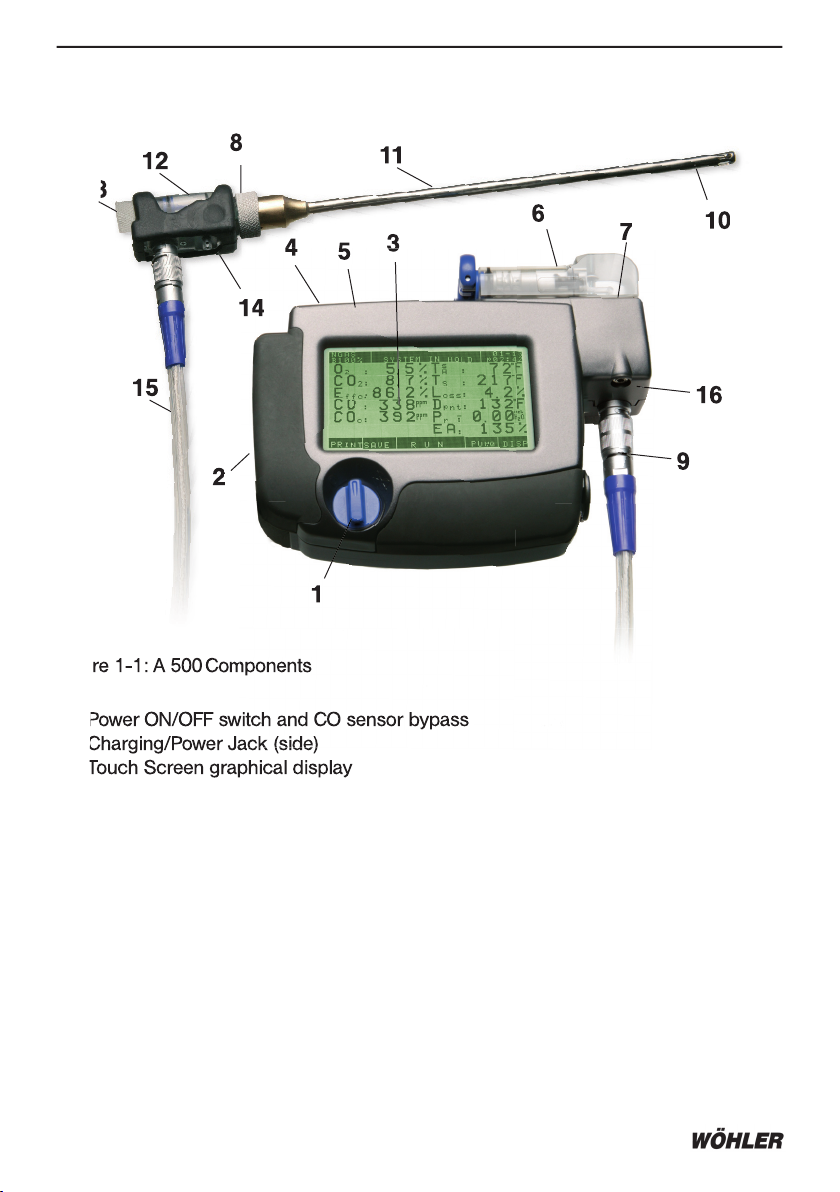
can operate from either an AC adapter, internal rechargeable batteries,
or standard AA alcaline batteries.
• Battery utilization display.
• Time and date display.
• Built-in memory for 850 individual combustion test records.
• Records can be recalled for printing or for transmission to a PC.
• All operator and data management functions are via the Touch-screen interface.
• Customer records can include the customer name, ID, device number, and com-
ments. Information is entered using the touch screen alphanumeric display.
• Customer data appears on the printout.

A 500
4 Technical Service Hotline: 978-750-9876
1. Introduction
1.2 Specifications
Eac
h
A
500
M
odel Measures and Displays:
O
2
: Oxygen from 0.1 to 20.9%
CO: Carbon monoxide, hydrogen compensated from 0 to 4000 ppm
T
A
TA
T
: Combustion air temperature from 0 to 257 °F (–20 to 125°C)
T
S
: Stack gas temperature from 32 to 1562 °F (0 to 850°C)
P
r
: Pressure: Stack draft in the range of ±16.00 inch H
2
O (±40.00 mbar)
Optional sensors include:
CO
HIGH
: Carbon monoxide from 4001 to 32,000 ppm
NO: Nitric oxide from 0 to 2000 ppm
NO
2
: Nitrogen dioxide from 0 to 500 ppm
SO
2
: Sulfur dioxide from 0 to 4000 ppm
Eac
h
A
500
M
odel Calculates and Displays:
CO
2
: Carbon dioxide from 0 to a maximum, fuel dependent value in percent
CO
C
: Carbon monoxide from 0 to 32,000 ppm when O2 referenced (user defi-
ned)
E
ffc
: Combustion efficiency from 0 to 100%
EA: Excess air from 0 to 250%
L
oss
: Stack loss from 0 to 100%
D
pnt
: Dew point temperature in °F or °C
Depending on additional optional sensors:
NO
C
: Nitric oxide from 0 to 32,000 ppm when O2 referenced (user defined)
NO
2C
: Nitrogen dioxide from 0 to 32,000 ppm when O2 referenced (user defi-
ned)
SO
2C
: Sulfur dioxide from 0 to 32,000 ppm when O2 referenced (user defined)
NO
x
: Oxides of nitrogen (NO + NO2) from 0 to 2500 ppm
NO
xc
: Oxides of nitrogen (NO + NO2) from 0 to 32,000 ppm when O2 refe
renced (user defined)
Fuels (User Selectable):
Natural Gas Wood Oil #2 Oil #6
Propane Kerosene Coal Digester Gas
Normal Operating Environment:
Temperature +50 to +104 °F (+10 to +40 °C)
Humidity 15 to 90% Relative Humidity, non-condensing
Air Pressure Atmospheric
Power:
4 ‘AA’ rechargeable Ni-MH batteries
Warm Up Time:
60 seconds

A 500
5
1. Introduction
Operating Time:
Approximately 12 hours of continuous operation with fully charged batteries. No time
limit if using the AC adapter.
Accuracy:
O
2
±0.3%
CO ±5% of reading (0 and 4000ppm)
CO
HIGH
±10% of reading from 4001 and 16,000 ppm
NO ±5% of reading or ±5 ppm, whichever is greater
NO
2
±5% of reading or ±5 ppm, whichever is greater
SO
2
±5% of reading or ±10 ppm, whichever is greater
TS: Stack Temp. ±4°F from 32 to 257°F (±2°C from 0 to 125°C)
±6°F from 258 to 481°F (±3°C from 126 to 249°C)
±8°F from 482 to 751°F (±4°C from 250 to 399°C)
±16°F from 752 to 1562°F (±9°C from 400 to 850°C)
T
A
TA
T
: Combustion-Air Temp. ±2°F (±1°C)
P
r
: Pressure ±3% of reading or ±0.02 inH2O (±3 Pa) whichever is
greater
Resolution:
O
2
0.1%
CO 1 ppm
CO
HIGH
2 ppm
NO 1 ppm
NO
2
1 ppm
SO
2
1 ppm
T
S
2°F (1°C)
T
A
TA
T
1°F (0.1°C)
P
r
0.01 inH
2
O (1 Pa)
Display:
2
¼
“ x 4
¼
“ backlit LCD, touch screen with alphanumeric, graphic display
Dimensions:
Height: 5.8 in. (147 mm)
Width: 7.6 in. (193 mm)
Depth: 2.0 in. (51 mm)
Weight:
Approximately 3.6 lbs (1.63 kg) with batteries and probe

A 500
6 Technical Service Hotline: 978-750-9876
1. Introduction
1.3 A 500 Components and Controls
1. Power ON/OFF switch and CO sensor bypass
2. Charging/Power Jack (side)
3. Touch Screen graphical display
4. IrDA port (top)
5. Battery compartment (back)
6. Water trap and filter
7. Water stop filter (inside)
8. Combustion air thermocouple /socket (front)
9. Connector for probe and hose assembly
10. Thermocouple
11. Probe
12. Probe assembly
13. Coarse probe filter (inside) and Plexiglas plug
14. Secondary pressure inlet
15. Combined gas and power hose
16. Ambient temperature plug
Figure 1-1: A 500
1
3
8
1. Power ON/OFF switch and CO sensor bypass
2. Charging/Power Jack (side)
3. Touch Screen graphical display
Figure 1-1: A 500
Components
Components
11
3
7
2
3
3
4
4
1
8
6
10
9
11
1
2
1
1
4
1
5
16
5
5

A 500
7
1. Introduction
Figure 1-2: Display Controls in Combustion Test Run Mode
Figure 1-3: Display Controls in Combustion Test Hold Mode
System Status - Hold mode
Touch to output dis-
played test data from
IRDA port
Touch to save the
current test data to
a customer memory
location
Touch to re-enter run
mode and continue
measuring
Touch to save the
Touch to re-enter run
Touch to enter GRA-
PHIC mode to select
individual sensor to
graph
Touch to zero
pressure sensor
Touch to freeze
current displayed
values
Touch to turn pump
off for pressure
measurements
PUM2 clean out
pump running
Touch to toggle
between combus-
tion and emission
screens
Select fuel and re-
maining battery life
Touch to enter fuel
selection screen
Customer Information
Touch to enter customer
data input and management
screen
Current date (mm-dd)
and time (
a
m/
p
p
m
hour: minute)
NGAS
B 95%
04-06
p03:36
Customer Name
Pr = 0
GRAPH PUM1 DISP
H O L D
T
A
TA
T
s
: 68°F
T
S
: 374°F
L
OSS
: 17.4 %
D
pnt
: 130°F
P
r
:- 0.0
2
EA
:
21%
O
2
: 4.0 %
CO
2
: 9.5 %
E
ffc
: 82.6 %
CO
: 8
PPM
CO
C
: 9
PPM
in
ch
H
2
O
NGAS
B 95%
04-06
p03:36
Customer Name
SAVE
PRINT PUM1 DISP
R U N
T
A
TA
T
s
: 68°F
T
S
: 374°F
L
OSS
: 17.4 %
D
pnt
: 130°F
P
r
:- 0.0
2
EA
:
21%
O
2
: 4.0 %
CO
2
: 9.5 %
E
ffc
: 82.6 %
CO
: 8
PPM
CO
C
: 9
PPM
in
ch
H
2
O
SYSTEM IN HOLD

A 500
8 Technical Service Hotline: 978-750-9876
2. Getting Started
Important. Please ensure the batteries are fully charged before use.
2.1 Turning on the A 500
1. Turn the analyzer ON by rotating the OFF/ON switch to its “I” position (No. 1 Figure
1-1). This starts the pump motor. The LCD should briefly display the WÖHLER A500
logo, and software version number. The screen also displays information on the to-
tal number of memory locations available, the remaining battery capacity expressed
as a percent, and the number of customer records currently stored (loaded). A
menu across the bottom of the screen allows the operator to access the functions
shown in Figure 2-2.
2. Getting Started
Lithium battery
voltage - replace
battery at 2.5 V
Number of memo-
ry locations used
Battery
life re-
maining
Touch
to enter
Setup
screen
menu
Total number of
memory locations
available
Touch
to enter
Data
screen
menu
Touch to
return to
factory
defaults
Touch
to enter
display
option
screen
Touch to
edit CO
limit (COP
starts
above
these
limit)
Touch to enter
Sensor Diagno-
sis screen
life re-
Touch to
Figure 2-1: Initial Turn-ON Screen and Menu Controls
DATASETUP DISP DIAGDEFLT CO_L
3.56
A 500
USA Version 1.
1
85
0 customers 4 loaded
B
100%

A 500
9
2. Getting Started
2.2 SET UP
Before using your A500 for a combustion test the following parameters or settings
must be entered or changed:
Time and Date
Measurement Units
Printer Protocol
Probe Calibration Factors
Oxygen Reference
NOTE: The
A500
r
etains its last settings until reset by the user to either the fac-
tory default settings or to new user selections.
2.3 Factory Defaults
The A 500 has been set up at the factory for the following defaults:
Time and Date Current time (EST) and date
Temperature °F
Pressure inchH2O
Emissions Unit of Measure ppm
O2 Reference 3%
Memory Formatted – no records
These settings can be changed as described below.
2.4 Setup Screen Controls
The Setup Screen is accessed by touching the SETUP key (lower left) after the A 500
is first turned ON and while its initial Turn-ON Screen (see Figure 2-1) is displayed.
(screen shows for approximately 5 seconds).
Figure 2-2: Initial Turn On Screen
DATASETUP DISP DIAGDEFLT CO_L
3.56
A 500
USA Version 1.
1
85
0 customers 4 loaded
B
100%

A 500
10
Technical Service Hotline: 978-750-9876
Figure 2-3: Setup Screen Controls
2.5 Connecting the Probe and Hose
Plug the probe tube into the probe handle by aligning the three prongs with the appro-
priate holes in the probe handle and push together snugly, and then secure by scre-
wing on the retaining collar. Connect the hose assembly to the probe handle and to
the analyzer by first aligning red marks on each connector, inserting then twisting the
connector clockwise until locked into place.
Important: For accurate temperature measurements, the probes calibration
factor must be entered into the analyzer per Section 5.4 Calibration Factors.
The calibration factors for the probe and combustion-air probe shipped with
the A500
from the factory have already been entered. Reentry of the calibration
factor only needs to be performed if a new or different probe is used.
2.6 Connecting the Combustion-Air Probe
Plug the Combustion-Air Temperature Probe (T
A
Plug the Combustion-Air Temperature Probe (TA
Plug the Combustion-Air Temperature Probe (T
) into the plug on the A500
located just
in front of the hose connector. (No. 16, Figure. 1-1). The A500 is supplied with a 1
¼
inch temperature probe. This short probe is used when the primary air source for the
burner is room air. Longer length probes are available for situations where a burner’s
combustion air is being drawn in from an outside source.
2. Getting Started
Touch to
enter Date
& Time
Set up
screen
menu
Touch to
enter Measu-
rement Unit
selection
screen
Touch to
enter printer
/IRDA selec-
tion screen
Touch to enter
thermocouple
calibration input
screen
Touch to
enter % O
2
re-
ference input
screen
To return to
initial Turn On
screen
MUNITD&T O2r ESCPRINT PROBE
3.56
A 500
USA Version 1.
1
85
0 customers 4 loaded
B
100%

A 500
11
2.7 Battery Charging and replacement
The A500 comes with 4 rechargeable AA batteries which can be charged while in the
analyzer. To charge, plug the supplied AC adapter into a 120 VAC outlet, then plug the
adapter’s DC output plug into the A 500’s power jack (No. 2, Figure 1-1). The A500
can be operated while its batteries are being charged when using the Fast Charger
(suplied with unit) (P/N 9042). The AC adapter supplied with the A500 does not identify
the charging status of the batteries. To ensure long battery life, completely discharge
the batteries before charging. It takes approximately 10 to 12 hours to fully charge
new batteries with the standard recharger. When fully charged the charger will auto-
matically switch to a trickle charge mode. The batteries can also be removed from the
unit and charged using an external universal charger. When reinstalling batteries it is
important to ensure the correct polarity position for each battery as indicated on the
inside of the battery housing.
If recharging batteries is not possible, regular disposable batteries may be used. The
battery cover located on the back of the unit can be removed by pushing the latch
down and then lifting the cover up. WARNING: FIRE HAZARD - DO NOT ATTEMPT TO
RECHARGE DISPOSABLE BATTERIES
The remaining battery life is shown as a percent and is displayed in the top-left hand
corner of the screen. The A500 has an automatic, low power conservation feature that
turns OFF the backlight and displays the warning message “** LOW BATTERY **” on
the screen when remaining battery life get very low. While this reduces the screens
visibility, it allows for all remaining battery power to be used to help complete whatever
activity the user was engaged in.
2. Getting Started

A 500
12
Technical Service Hotline: 978-750-9876
3. Operating the A 500 for a Combustion Efficiency Test
NOTE: This chapter assumes that the user of the A 500
has the required techni-
cal knowledge to properly identify the sampling point(s) for the type of equip-
ment involved.
3.1 Turning ON the Analyzer
Please ensure the batteries are fully charged before use.
1. Turn the analyzer ON by rotating the OFF/ON switch to its “I” position (No. 1, Figure
1-1). This starts the pump motor. The LCD should briefly display the WÖHLER A 500
logo, and software version number, the total number of memory locations available,
the remaining battery capacity expressed as a percent, and the number of customer
records currently stored (loaded). A menu across the bottom of the screen allows the
operator to access the functions shown in Figure 2-2. (this is displayed for approx. 5
sec)
2.
Do not attemp t
o use the analyzer until its calibration cycle is complete
!
3. Operating the A 500

A 500
13
Figure 3-2: Combustion Test Screen and Controls
3.2 Select the Fuel type
The A500 defaults to the most recently selected fuel as shown in the upper-left hand
corner of the display. To select a different fuel, touch the Fuel name to display the Fuel
Selection Screen (see Figure 3-2). Touch the desired fuel name to select that fuel. The
A500 will automatically return to the Run Mode screen.
Figure 3-3: Fuel Selection Screen
3. Operating the A500
NGAS = Natural Gas
OIL2 = #2 Fuel Oil
COAL = coal
DGAS = Digester Gas
OIL6 = #6 Fuel Oil
WOOD = Wood
LPG = Liquid Propane
KERO = Kerosene
TEST = Test Gas
(service only)
The bottom five buttons on the
screen are displayed but inactive
in Fuel Selection screen
NGAS
B 95%
04-06
p03:36
Customer Name
Pr = 0
GRAPH PUM1 DISP
H O L D
T
A
TA
T
s
: 68°F
T
S
: 374°F
L
OSS
: 17.4 %
D
pnt
: 130°F
P
r
:- 0.0
2
EA
:
21%
O
2
: 4.0 %
CO
2
: 9.5 %
E
ffc
: 82.6 %
CO
: 8
PPM
CO
C
: 9
PPM
in
ch
H
2
O
: 4.0 %

A 500
14
Technical Service Hotline: 978-750-9876
3.3 The Combustion Test Screen
Figure 3-4: Combustion Test Screen and Controls
3. Operating the A 500
O
2
= % Oxygen
CO
2
= % Carbon Dioxide
Effc = % Combustion Effi-
ciency
CO = Carbon Monoxide
CO
c
= Carbon Monoxide
referenced to a % of O
2
T
A
TA
T
s
= Combustion-Air
Temp.
s
hort probe
T
A
TA
T
l
= Combustion-Air
Temp.
l
ong probe
TS = Stack temperature
Loss = % Stack loss (100%
- Effc)
Dpnt = Dew Point temperatu-
re
Pr = Pressure / Draft
EA = % Excess Air
3.4 Navigation to the Emission screen FUEL SELECTION
The operator can easily toggle back and forth between the Combustion Results screen
and the Emissions screen by simply pressing the DISP button on the bottom right of
the screen.
Figure 3-5: Display Toggle Screen ControlThis will result in the following screen Dis-
play:
NGAS
B 95% 04-06
p03:36
Customer Name
Pr = 0
GRAPH PUM1 DISP
H O L D
T
A
TA
T
s
: 68°F
T
S
: 374°F
L
OSS
: 17.4 %
D
pnt
: 130°F
P
r
:- 0.0
2
EA
:
21%
O
2
: 4.0 %
CO
2
:
9.5 %
E
ffc
: 82.6 %
CO
: 8
PPM
CO
C
: 9
PPM
in
ch
H
2
O

A 500
15
Figure 3-6: Emission Test Screen and Controls
3.5 Touch Screen Controls and their Function
HOLD Places the analyzer on hold and freezes the display at the current
values.
RUN Restarts a combustion test that was placed on hold.
GRAPH After this key is pressed; touch the name of the test value to be displayed
as a graph. Refer to Section 3.6 Using the Graph Function.
SAVE Saves current test data in memory. Test data can then be reviewed or
printed at a later time. Refer to Section 4.4 Saving Test Data.
PRINT Prints all currently displayed test data. Refer to Section 4.9 Printing.
Pr=0 Zeros the pressure sensor to the currently applied pressure – DO NOT
zero pressure sensor with probe in stack.
Notes: Units of measure (ppm; mg/m3; #/GBTU; g/GJ), %O
2
reference, pressure units,
and temperature units are all user selectable. Refer to Section 5.2 Selecting Measure-
ment Units.
3.6 Using the Graph Function
The GRAPH key is used to produce a graph of any measured or calculated value
shown on the Combustion Test Screen. This function is useful for observing a trend of
a measured value over a 90 second time period.
To start the graph function:
1. With the analyzer operating in its Run Mode, touch the GRAPH key to display the
message “TOUCH SENSOR”, at top of display.
PUM1 DISP
3. Operating the A 500
NO = Nitric Oxide
NO
2
= Nitrogen Dioxide
NOx = Oxides of Nitrogen
SO
2
= Sulfur Dioxide
O
2
REF = % Oxygen Reference
NOc = Nitrogen Oxide refe-
renced to a % of O
2
NO
2c
= Nitrogen Dioxide refe-
renced to a % of O
2
NO
xc
= Oxides of Nitrogen
referenced to a % of O
2
SO
2c
= Sulfur Dioxide referenced
to a % of O
2
NGAS
B 95% 04-06
p03:36
Customer Name
Pr = 0
GRAPH PUM1 DISP
H O L D
NO
c
: 19 ppm
NO
2c
: 6 ppm
NO
xc
: 25 ppm
SO
2c
: - - - pp
m
NO
: 18 ppm
NO
2
:
6 ppm
NO
x
: 24 ppm
SO
2
:
- - - ppm
O
2 REF
:
3 %

A 500
16
Technical Service Hotline: 978-750-9876
2. Touch the displayed name of the combustion test value to be graphed.
3. A graph of the selected combustion test value is now be drawn from left to right on
the screen. Along with the graph the display will also show the current numerical value.
In the example below, a graph of the oxygen value shows that the oxygen level has
dropped from a high of 20.9 % to its current value of 4.0 %.
Figure 3-7: Graphic Mode Screen
4. At the end of 90 seconds, a new graph is started. Touch the HOLD key to freeze the
graph. Touch the RUN key to resume graphing.
5. Exit the graph mode by again touching the GRAPH key.
3. Operating the A 500

A 500
17
3.7 Automatic CO Sensor Protection
When the CO sensor is exposed to levels in excess of CO-limit (adjustable from 500-
4000ppm. see figure 2-1 on page 8), a clean out pump starts and diverts the flue gas
from the CO sensor.
With COhigh sensor installed:
The clean out pump starts when the excess CO level for the CO low sensor is reached.
The clean out pump will automatically shut off after the CO is cleared.
Without COhigh sensor:
The clean out pump starts when the excess CO level for the COlow sensor is reached.
You must remove the probe from the stack and wait for the CO level to go to zero.
Then you can press the PUM2 button on the display and the CO clean out pump will
stop and the display will read PUM1.
3.7.1 Manual CO sensor Protection
The A 500 has a high CO safety cutoff valve to protect the base 4000 ppm CO sensor
from becoming saturated. If the detected CO level rises above 4000 ppm the A500
beeps and a message “CO:PROTECT ON” appears on the display. At this notice the
operator should move the OFF/ON switch to its CO position (CO). This causes the gas
sample to bypass the CO sensor, protecting it from being exposed to excessive levels
of carbon monoxide. The message will remain displayed as a reminder that the CO
sensor has been bypassed. To clear this message ensure the probe is away from any
high CO areas; move the OFF/ON switch back to its I position; flush the unit with fresh
air; then place the unit on HOLD.
Pr = 0 H O L D PUM1 DISP
If the optional CO High sensor is installed the analyzer will continue to display CO
levels up to 32,000 ppm. When the detected CO level drops from above 4000 ppm to
below 1000 ppm, the unit beeps and displays the message “CO: PROTECT OFF,” infor-
ming the operator to move the OFF/ON switch back to its I position.
Figure 3-8: CO Sensor Bypass Switch
3. Operating the A 500
operator should move the OFF/ON switch to its CO position (CO). This causes the gas

A 500
18
Technical Service Hotline: 978-750-9876
The analyzer should not be exposed to flue gas with high moisture content if the
analyzer has been cooled to below freezing for a long period of time (e.g. overnight in
a vehicle). It is recommended that the hose be removed from the analyzer after a day’s
usage and allowed to dry.
The waterstop filter (No.7, Figure 1-1) blocks water from entering the analyzer. If this
filter becomes saturated with water the analyzers pump will slow down and nearly stall.
The water stop filter should be replaced if this happens.
To access the water stop filter 1) remove the large heat exchanger; use the key on the
end to remove the screw on the top of the condensation block; 2) pull the block off
exposing the water stop filter; remove and replace; 3) reassemble condensation block.
Figure 3-10: Replacing the waterstop filter
3. Operating the A 500
Figure 3-9: Emtying the Water Trap
3.8 Condensation Precautions
Removing condensation from the gas sample is critical for the proper operation and
measurement accuracy of the unit. The A 500 has four condensate filters (Figure 3-11).
The amount of condensation in the water trap / filter assembly should be checked
before conducting a test and also observed during a test. The large heat exchanger
should be removed, emptied and dried before becoming completely full of water. The
cotton filter in the smaller heat exchanger should be replaced when it becomes wet
and the small heat exchanger emptied and dried.

A 500
19
3. Operating the A 500
Figure 3-11: A 500
Gas Channel and Filter Protection

A 500
20
Technical Service Hotline: 978-750-9876
3.9 Ending a Combustion Test
WARNING! HEAT HAZARD! Do Not Touch the probe after removing it from the
stack. Allow the probe to cool before handling (about 5 minutes).
When testing is complete, remove the probe from the stack and allow the analyzer
pump to run to purge the hose and analyzer with room air until normal ambient gas
readings are observed on the display. Turn OFF the analyzer by setting the OFF/ON
switch to its “O” position. When storing the analyzer, it is a good idea to empty the wa-
ter trap and dry it out. It is also suggested that you remove the hose and allow it to dry.
3.10 Using the Gas Sample Conditioner when Measuring NO
2
or SO
2
When measuring NO2 or SO
2
, the metal heat exchangers must be replaced with plastic
versions in the A 500’s condensation block. It is also highly recommended that a Wöh-
ler Peltier Cooler gas sample conditioner be attached to the probe assembly. The gas
sample conditioner removes water vapor from the gas sample preventing the formation
of water droplets inside the probe hose. If water droplets were to form inside the hose,
a portion of the NO
2
and SO
2
gas molecules in the gas sample would be removed by
the water resulting in inaccurate, lower-than-actual readings for these gases.
Refer to Appendix A for detailed information on how to install, operate, and maintain
the Gas Sampler Conditioner.
3.11 Status and Error Messages
The following is a list of status and error messages that appear in the top line of the
display while operating the analyzer.
Display Explanation
**LOW BATTERY**: Battery life below 4%.
FUEL SELECTION: Select the fuel being burned by touching the name of the approp-
riate fuel.
SYSTEM IN HOLD: The display is frozen at the values being displayed when the
HOLD key was pressed.
CO:PROTECT ON: If the unit is exposed to CO levels in excess of the pre-set excess
level, the CO clean out pump will start. If the unit has no COhigh
sensor installed you must remove the probe from the stack and
wait for the CO level in the analyzer to reach zero. Then you must
press the „PUM2“ button on the bottom of the display screen. This
will shut-off the CO clean out pump and you can begin testing
again. If the unit has a COhigh sensor installed the CO clean
out pump will start when the pre-set excess CO level has been
reached, however, you can continue testing and the COhigh sen-
sor will give you a reading up to 32,000ppm. When the CO(low)
3. Operating the A 500
Table of contents
Other Wohler Measuring Instrument manuals

Wohler
Wohler SP 22 User manual

Wohler
Wohler VAMP AC-3/M User manual

Wohler
Wohler LM25 Analog Series User manual

Wohler
Wohler CM 220 User manual

Wohler
Wohler SM 500 User manual

Wohler
Wohler SC 602 User manual

Wohler
Wohler M 603 User manual

Wohler
Wohler M 603 User manual

Wohler
Wohler M5 User manual

Wohler
Wohler Smart Connect SC 660 User manual

Wohler
Wohler DC 2000 User manual

Wohler
Wohler TA 420 User manual

Wohler
Wohler A 400 User manual

Wohler
Wohler CD 210 User manual

Wohler
Wohler VE User manual

Wohler
Wohler TI 410 User manual

Wohler
Wohler iVAM2-2 User manual

Wohler
Wohler DC 2000PRO User manual

Wohler
Wohler IQ 300 User manual

Wohler
Wohler H 420 User manual