Trotec BE49 User manual

TRT-BA-BE49-TC220328TTRT02-001-EN
BE49
EN
OPERATING MANUAL
DIGITAL MULTIMETER
2 EN
digital multimeter BE49
Table of contents
Notes regarding the instructions .........................................2
Safety .....................................................................................2
Information about the device................................................4
Transport and storage...........................................................7
Operation ...............................................................................7
Maintenance and repair ......................................................11
Errors and faults..................................................................12
Disposal ...............................................................................12
Notes regarding the instructions
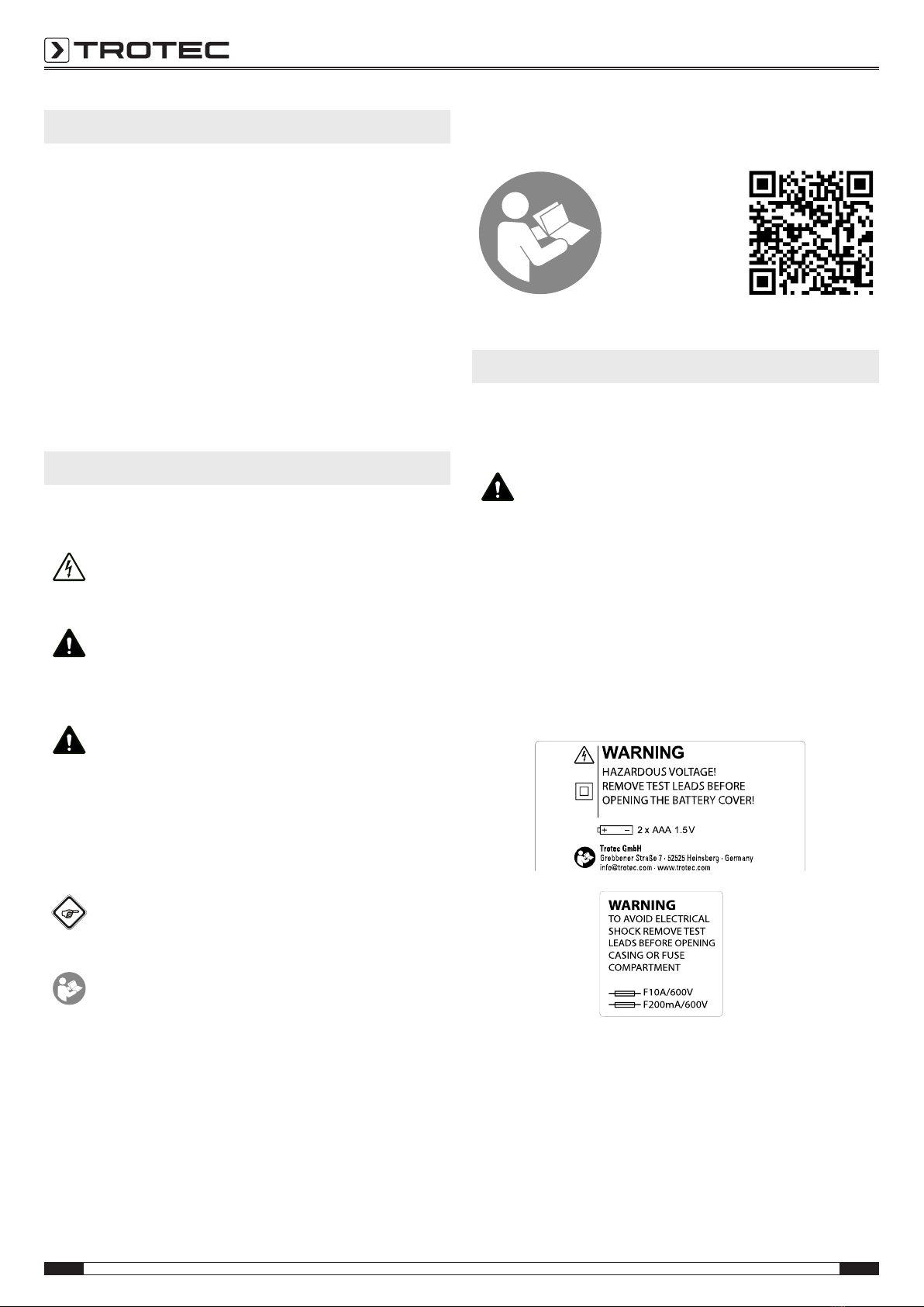
Symbols
Warning of electrical voltage
This symbol indicates dangers to the life and health of
persons due to electrical voltage.
Warning
This signal word indicates a hazard with an average
risk level which, if not avoided, can result in serious
injury or death.
Caution
This signal word indicates a hazard with a low risk
level which, if not avoided, can result in minor or
moderate injury.
Note
This signal word indicates important information (e.g.
material damage), but does not indicate hazards.
Info
Information marked with this symbol helps you to carry
out your tasks quickly and safely.
Follow the manual
Information marked with this symbol indicates that the
instructions must be observed.
You can download the current version of the instructions and
the EUdeclaration of conformity via the following link:
BE49
https://hub.trotec.com/?id=46447
Safety
Read this manual carefully before starting or using the
device. Always store the manual in the immediate vicinity
of the device or its site of use.
Warning
Read all safety warnings and all instructions.
Failure to follow the warnings and instructions may
result in electric shock, fire and/ or serious injury.
Save all warnings and instructions for future
reference.
• The device is supplied with warning signs. Prior to initial
start-up, make sure to paste the corresponding warning
signs in your local language, if available, over the ones
present at the rear of the device as described in the
Operation chapter. Otherwise, choose labels in a language
you know.
• Do not use the device in potentially explosive rooms or
areas and do not install it there.
• Do not use the device in aggressive atmosphere.
• Protect the device from permanent direct sunlight.
• Do not remove any safety signs, stickers or labels from the
device. Keep all safety signs, stickers and labels in legible
condition.
• Do not open the device.
EN 3
digital multimeter BE49
• Never charge batteries that cannot be recharged.
• Different types of batteries and new and used batteries
must not be used together.
• Insert the batteries into the battery compartment according
to the correct polarity.
• Remove discharged batteries from the device. Batteries
contain materials hazardous to the environment. Dispose
of the batteries according to the national regulations.
• Remove the batteries from the device if you will not be
using the device for a longer period of time.
• Never short-circuit the supply terminal in the battery
compartment!
• Do not swallow batteries! If a battery is swallowed, it can
cause severe internal burns within2hours! These burns
can lead to death!
• If you think batteries might have been swallowed or
otherwise entered the body, seek medical attention
immediately!
• Keep new and used batteries and an open battery
compartment away from children.
• Observe the storage and operating conditions (see
Technical data).
• Disconnect the measuring cables from the device before
replacing the batteries.
• Do not exceed the measuring range of a function specified
in the technical data.
• Always disconnect the measuring tips from the circuit
before changing the measuring mode.
• Proceed with the utmost care when measuring voltages
above 25VACrms or 35VDC. There is a risk of an electric
shock at these voltage levels.
• Ensure that the measuring area has zero potential and the
capacitors are discharged before you carry out diode,
resistance or continuity tests. Disconnect the measuring
lines from the measuring area before switching over the
device to diode, resistance or continuity tests if you have
previously carried out measurements on live components
Intended use
Only use the multimeter for measuring voltage, current or
resistance whilst adhering to the technical data.
To use the device for its intended use, only use accessories and
spare parts which have been approved by Trotec.
Foreseeable misuse
Do not use the device in potentially explosive atmospheres,
when wet or very humid.
Unauthorized modifications of the device are forbidden.
Personnel qualifications
People who use this device must:
• master the 5 safety rules of electrical engineering
– 1.De-energise
– 2.Secure against restart
– 3.Verify de-energised state (bipolar)
– 4.Earth and short-circuit
– 5.Cover neighbouring live parts
• use the measuring device in accordance with safe working
procedures.
• be aware of the dangers that occur when working with
electric devices in damp areas.
• take measures to protect themselves from direct contact
with live parts.
• have read and understood the instructions, especially the
Safety chapter.
Residual risks
Warning of electrical voltage
Electric shock due to insufficient insulation! Check the
device and the measuring cables for damages and
proper function before each use.
If you detect damages, do not use the device any
longer.
Do not use the device when either the device or your
hands are damp or wet!
Do not use the device when the battery compartment
or the housing is open.
Warning of electrical voltage
Electric shock due to contact with live parts! Do not
touch any live parts. Secure neighbouring live parts by
covering them or by switching them off.
Warning of electrical voltage
Electric shock due to contact with live parts! When
using the measuring tips, make sure not to reach
behind the protection against contact.
Warning of electrical voltage
There is a risk of a short-circuit due to liquids
penetrating the housing!
Do not immerse the device and the accessories in
water. Make sure that no water or other liquids can
enter the housing.
Warning of electrical voltage
Work on the electrical components must only be
carried out by an authorised specialist company!
Warning
Risk of suffocation!
Do not leave the packaging lying around. Children may
use it as a dangerous toy.

4 EN
digital multimeter BE49
Warning
The device is not a toy and does not belong in the
hands of children.
Warning
Dangers can occur at the device when it is used by
untrained people in an unprofessional or improper way!
Observe the personnel qualifications!
Caution
Keep a sufficient distance from heat sources.
Note
To avoid damages to the device, make sure that the
correct measuring range is selected before carrying out
a measurement.
If you are unsure, select the largest measuring range.
Remove the measuring cables from the measuring
point before changing the measuring range.
Note
To prevent damages to the device, do not expose it to
extreme temperatures, extreme humidity or moisture.
Note
Do not use abrasive cleaners or solvents to clean the
device.
Note
Before commissioning, check the function of the
device at a known voltage source, e.g. on a known and
safe230V voltage source or on a known and safe
9Vbattery. Select the correct measuring range!
Information about the device
Device description
The multimeter is a battery-powered, mobile hand-held
measuring device with an extensive range of measurement
possibilities.
The device is equipped with the following functional properties
and equipment features:
• Automatic/ manual range selection
• LCD display
• Can also be operated while wearing gloves
• Fold-out stand
• Safety CATIII (600V)
• AC and DCvoltage measurement
• Measurement of direct and alternating currents
• Resistance measurement
• Diode testing function
• Acoustic continuity testing
• Hold function
Overvoltage protection and measurement category
The power grid is permanently subjected to short-time voltage
peaks, the so-called voltage surge, which can be very low, for
instance when a light switch is actuated, but also very high
when a network operator switches over power lines. The height
of the surge voltage depends on the position within a low-
voltage network in which a device/machine is operated. The
closer this position is to the supply line, the higher is the surge
voltage to be expected. This means that an electricity meter of a
house must be able to absorb a higher surge voltage than a
Wlan router.
For the purpose of simplification, the power grid is divided into
four overvoltage categories. A rated surge voltage is assigned to
overvoltage categories in each case, indicating the voltage
peaks for which a device has to be designed:
Overvoltage
category
Rated surge
voltage
Examples
CAT I 1500V Devices with power adapter:
e.g.: laptops, monitors,
telephones
CAT II 2500 V Devices with cold-device plugs:
e.g.: household appliances,
printers, laboratory equipment,
telephone system
CAT III 4000 V Devices without a plug:
e.g.: sub-distributions, cables,
sockets, CNC machines,
construction cranes, energy
storage systems
CAT IV 6000 V Devices at the feed point:
e.g.: electricity meters, primary
overcurrent protection devices,
main switches
In line with the overvoltage categories there are measurement
categories defining the permissible scope of application of
measurement and testing devices for electrical equipment and
systems in low-voltage networks.
The design of a measurement device determines in which
environments and for which voltages it can be safely used. What
is important in this connection for example is the touchability of
live parts, anti-kink protection guards on the measuring lines or
the insulation. Depending on the design details, the
measurement device can carry out safe measurements up to a
specific voltage in one or several overvoltage categories. The
measurement category is specified on the measurement device
as well as in the operating manual.
The measurement category is indicated including the maximum
voltage height, which can either be 300, 600 or 1000Volt. The
designation CAT III/1000 V for example means that the
measurement device may be used in low-voltage indoor
installation for voltages up to 1000volts.

EN 5
digital multimeter BE49
Often several values are indicated on the device, for instance
CAT III/ 1000 V and CAT IV/600 V. In these cases, different
maximum voltages apply to the stated scopes of application. If
no measurement category is specified, the measurement device
is only considered as safe in measurement category CAT I.
Device depiction
1
3
4
6
7
2
8
12
11
9
14
10
13
5
No. Designation
1 LC display
2HOLDbutton
3 Illumination button
4 Rotary switch
5 mA/V/Ω socket
6 COMsocket
7 Red measuring tip
8 Black measuring tip
9 Fold-out stand
10 Fuse compartment (below stand)
11 Battery compartment
12 10Asocket
13 MODEbutton
14 RANGEbutton
Rotary switch
15 16
17
18
19
20
21
No. position Description
15 OFF Device is switched off.
16 ACvoltage:
200mV to 600V
17 DCvoltage:
200mV to 600V
18 Resistance measurement:
200Ω to 20MΩ
Diode test/ continuity measurement
19 Direct and alternating current:
up to 200µA
20 Direct and alternating current:
up to 200mA
21 Direct and alternating current:
up to 10A
6 EN
digital multimeter BE49
Technical data
General characteristics
Parameter Value
Diode test max. testing current of 0.3mA, open-
circuit voltage of 1.5VDC (typically)
Continuity test An acoustic signal is emitted if the
resistance amount to less than
150Ω.
Input impedance 10MΩ (VDC and VAC)
Frequency range 50Hz to 400Hz (AAC and VAC)
LC display 2000 Count LCD
Measuring range
exceeded
OL will be displayed.
Polarity Automatic (no indication for positive);
minus (-) sign for negative
Measuring speed 2x per second, nominal
Battery indication BAT is indicated if the battery voltage
drops below the operating voltage
threshold
Battery 2x AAAbattery, 1.5V
Fuses Measuring range µA/mA:
200mA/600V (fast acting)
Measuring range 10A: 10A/ 600V
(fast acting)
Operating temperature 5°C to 40°C (41°F to 104°F)
Storage temperature -20°C to 60°C (-4°F to 140°F)
Type of protection IPX0
Relative humidity Operation: max. 80% up to 31°C
(87°F), linear decreasing to 50% at
40°C (104°F)
Storage: <80%
Operating height above
sea level
Maximum 2000 m (7000ft)
Weight 170g
Dimensions (lengthx
widthx height)
121mmx 65mmx 35mm
Automatic switch-off after 15minutes of inactivity
Safety This measuring device is designed for
indoor use and complies with over-
voltage category CATIII(600V).
Measuring ranges
Function Measuring
range
Resolution Accuracy
DCvoltage
(VDC)
200mV 0.1mV ± (0.8%
+2digits)
2000mV 1mV ± (1.5%
+2digits)
20V 0.01V
200V 0.1V
600V 1V ± (2.0%
+2digits)
AC voltage
(V AC, 50 / 60 Hz)
200mV 0.1mV ± (1.5%
+35digits)
2000mV 1mV ± (1.8%
+8digits)
20V 0.01V
200V 0.1V
600V 1V ± (2.5%
+8digits)
Direct current
(ADC)
200µA 0.1µA ± (1.0%
+3digits)
2000µA 1µA ± (1.5%
+3digits)
20mA 10µA
200mA 100µA
10A 10mA ± (2.5%
+5digits)
Alternating current
(AAC)
200 µA 0.1µA ± (1.5%
+5digits)
2000µA 1µA ± (2.0%
+5digits)
20mA 10µA
200mA 100µA
10A 10mA ± (3.0%
+7digits)
Resistance
(Ω)
200 Ω 0.1 Ω ± (1.0%
+4digits)
2000 Ω 1 Ω ± (1.5%
+2digits)
20kΩ 0.01kΩ
200kΩ 0.1kΩ
2000kΩ 1kΩ ± (2.5%
+3digits)
20MΩ 10kΩ ± (3.5%
+5digits)
Note:
The accuracy is based on an ambient temperature of 18°C to
28°C and a relative humidity of less than 80%.
The accuracy specification consists of two values:
• %value referring to the reading: Corresponds to the
accuracy of the installation to be measured.
• +digits: Corresponds to the accuracy referring to the
analogue to digital converter.
EN 7
digital multimeter BE49
Scope of delivery
• 1xMultimeter
• 1 x Safety measuring lines with test probes
• 2x AAAbattery
• 1x Quick guide
Transport and storage
Note
If you store or transport the device improperly, the
device may be damaged.
Note the information regarding transport and storage of
the device.
Transport
When transporting the device, ensure dry conditions and and
protect the device from external influences e.g. by using a
suitable bag.
Storage
When the device is not being used, observe the following
storage conditions:
• dry and protected from frost and heat
• protected from dust and direct sunlight
• the storage temperature complies with the values specified
in the Technical data
• Remove the batteries from the device.
Operation
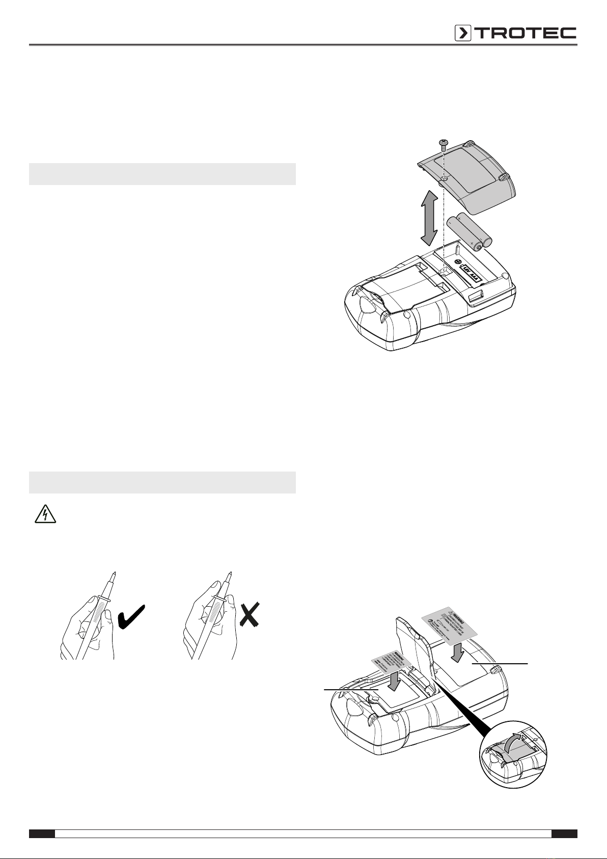
Warning of electrical voltage
Electric shock due to contact with live parts! When
using the measuring tips, make sure not to reach
behind the protection against contact.
Inserting the batteries
Insert the batteries before first use.
Note
Disconnect the measuring tips from the device before
opening the battery compartment.
Note
Make sure that the surface of the device is dry and the
device is switched off.
1. Loosen the screw at the battery compartment(11).
2. Open the battery compartment.
3. Insert both batteries in the battery compartment(+/-) with
correct polarity.
4. Close the battery compartment and retighten the screw.
Attaching the warning signs
Prior to initial start-up, check whether the warning signs at the
rear of the device are in your local language, if not, paste the
proper ones over it. Warning signs in your native language are
supplied along with the device. Please proceed as follows to
attach the warning signs to the rear of the device:
1. Remove the label for the battery compartment in your local
language from the supplied film.
2. Affix the label in the intended position on the battery
compartment(11) of the device.
3. Remove the label for the fuse compartment in your local
language from the supplied film.
4. Fold out the stand on the back of the device and affix the
label in the intended position on the fuse compartment(10)
of the device.
10
11

8 EN
digital multimeter BE49
Undefined displays
If measuring inputs are open or touched by hand, this can lead
to undefined displays. This is not a malfunction but a reaction of
the sensitive measuring input to existing interference voltages.
Normally, when there is no high interference level at the
workplace or in case of a short circuit at the measuring input
zero is displayed immediately. Or, if the measuring object is
connected, the exact measured value is displayed. Fluctuations
in the displayed value by some digits are systemic and within
the tolerance.
If the resistance measuring range, the continuity testing range
or the diode test was selected and the measuring input is open,
the OLindication (exceedance of the measuring range) will be
displayed.
IMPORTANT INFORMATION ON THE MEASURING PROCESS!
Warning of electrical voltage
Improper handling of the measuring device entails a
risk of electric shock!
Before carrying out voltage measurements, observe the
following:
• Never apply a voltage exceeding the rated nominal voltage
of the measuring device between the connections or
between the connections and earth (see imprint on the
housing).
• Check the measuring tips for damaged insulation and for
continuity. Replace damaged measuring tips.
• Check the insulation of the measuring device sockets.
• Before using the measuring device, check its functionality
by carrying out measurements with a known voltage.
• First connect the measuring tip connected to earth and
afterwards the live measuring tip. When disconnecting the
measuring tips, proceed in reverse order, i.e. disconnect
the live measuring tip first.
• Prior to every voltage measurement make sure that the
measuring device is not set to the current measuring
range.
• If the device indicates an exceedance of the measuring
range(OL) immediately after being connected to the
measuring object, first switch off the circuit at the
measuring object, then immediately remove the measuring
tips from the measuring object.
• Do not switch any motors in the measuring circuit on or off
during a measurement. Voltage peaks caused by a switch-
on or switch-off can damage the measuring device.
Manual range selection
The device is equipped with an auto-range function, i.e. it
adjusts the indication of the measured value to the value that
has been measured.
The RANGE button(14) is used to change the display of the
measured value by changing the number of decimal places. To
do so, press the RANGEbutton until the measured value is
indicated as desired.
Press the RANGEbutton for approx.2seconds to return from
manual range selection to the auto range function.
Measuring DCvoltage
1. Set the rotary switch to position .
2. Insert the plug of the black measuring tip into the
COMmeasuring socket and the plug of the red measuring
tip into the V/Ωmeasuring socket.
3. Connect both measuring tips to the measuring object with
correct polarity (black to minus, red to plus).
ðIf the input voltage is negative, a minus(-) will appear in
front of the measured value on the display.
ðThe measured value will be indicated on the display.
4. If the OLindication (exceedance of the measuring range)
appears after the manual range selection, immediately
switch over to the respectively next higher range
(RANGEbutton). If the OLindication appears and the
maximum range has been set already or in case of the
automatic range selection, immediately switch off the
voltage supply at the measuring object and disconnect the
measuring device from the measuring object.
ðThe measured value will be indicated on the display.

EN 9
digital multimeter BE49
Measuring ACvoltage
1. Set the rotary switch to position .
2. Insert the plug of the black measuring tip into the
COMmeasuring socket and the plug of the red measuring
tip into the V/Ωmeasuring socket.
3. Connect both measuring tips to the measuring object.
ðIf the input voltage is negative, a minus(-) will appear in
front of the measured value on the display.
ðThe measured value will be indicated on the display.
4. If the OLindication (exceedance of the measuring range)
appears after the manual range selection, immediately
switch over to the respectively next higher range
(RANGEbutton). If the OLindication appears and the
maximum range has been set already or in case of the
automatic range selection, immediately switch off the
voltage supply at the measuring object and disconnect the
measuring device from the measuring object.
ðThe measured value will be indicated on the display.
Current measurements
Note
Never connect a voltage source to the multimeter's
measuring sockets when a current measuring range is
selected. Otherwise the device could be damaged.
Before carrying out current measurements, observe the
following:
• The voltage in the measuring circuit must not be higher
than 600V (CATIII) to ground.
• For measuring higher currents starting at 200mA in the
10Arange, one must observe a maximum measurement
duration of 30s each with an intermission of 15minutes
between two measurements. Otherwise, the device may
be damaged due to excessive heating.
1. For measuring the current, interrupt the circuit to be
checked and connect the measuring device in series with
the consumer in this circuit.
2. Depending on the expected measuring current, turn the
rotary switch to position , or .
3. Use the MODE button(3) to select the desired measuring
mode (for direct current: DCindication, for alternating
current: ACindication).
4. Insert the plug of the black measuring tip into the
COMmeasuring socket and the plug of the red measuring
tip into the µA/mA or 10Ameasuring socket – depending
on the selected range.
5. Switch off the voltage supply at the measuring object and
connect the measuring tips to the measuring object. For
direct current, make sure that the polarity of the
connection to the measuring object is correct (in series;
red to plus, black to minus).
6. Switch the measuring circuit back on and read the
measured value from the display.
7. If the OLindication (exceedance of the measuring range)
appears after the manual range selection, immediately
switch over to the respectively next higher range. If the
OLindication appears and the maximum range has been
set already or in case of the automatic range selection,
immediately switch off the voltage supply at the measuring
object and disconnect the measuring device from the
measuring object.
Info
If you have selected the 10A range for safety's sake,
but the measuring current amounts to less than
200mA, switch the measuring circuit back off. Plug
the red measuring tip into the mAsocket and select a
measuring range in the mArange. Switch the
measuring circuit back on.
Info
If there is no indication and all connections have been
established correctly, the cause of the fault may be a
defective internal fuse protecting the current
measuring ranges (see chapter Fuse replacement).
10 EN
digital multimeter BE49
Measuring resistance
Warning of electrical voltage
Before carrying out resistance, continuity or diode
measurements, switch off the current of the electric
circuit and discharge all capacitors.
1. Set the rotary switch to the resistance measuring range
(Ω//CAP), then use the MODEbutton to select the
resistance measurement (MΩindication).
2. Insert the plug of the red measuring tip into the
V/Ωmeasuring socket and the plug of the black measuring
tip into the COMmeasuring socket.
3. Connect the measuring tips to the measuring object. The
measuring device may take some time to display a stable
value. This is due to the measuring principle and not a
malfunction.
ðThe measured value will be indicated on the display.
4. Turn the rotary switch to the position that is closest to the
indicated value but does not fall below it.
ðThe measured value will be indicated on the display.
Note:
In case of very low resistance values (400Ωrange) the internal
resistors of the measuring tips and sockets might lead to a
falsified display. The resistance value displayed in case of short-
circuited measuring tips will be put down in writing and later
subtract from the measured value for the subsequent
measurements.
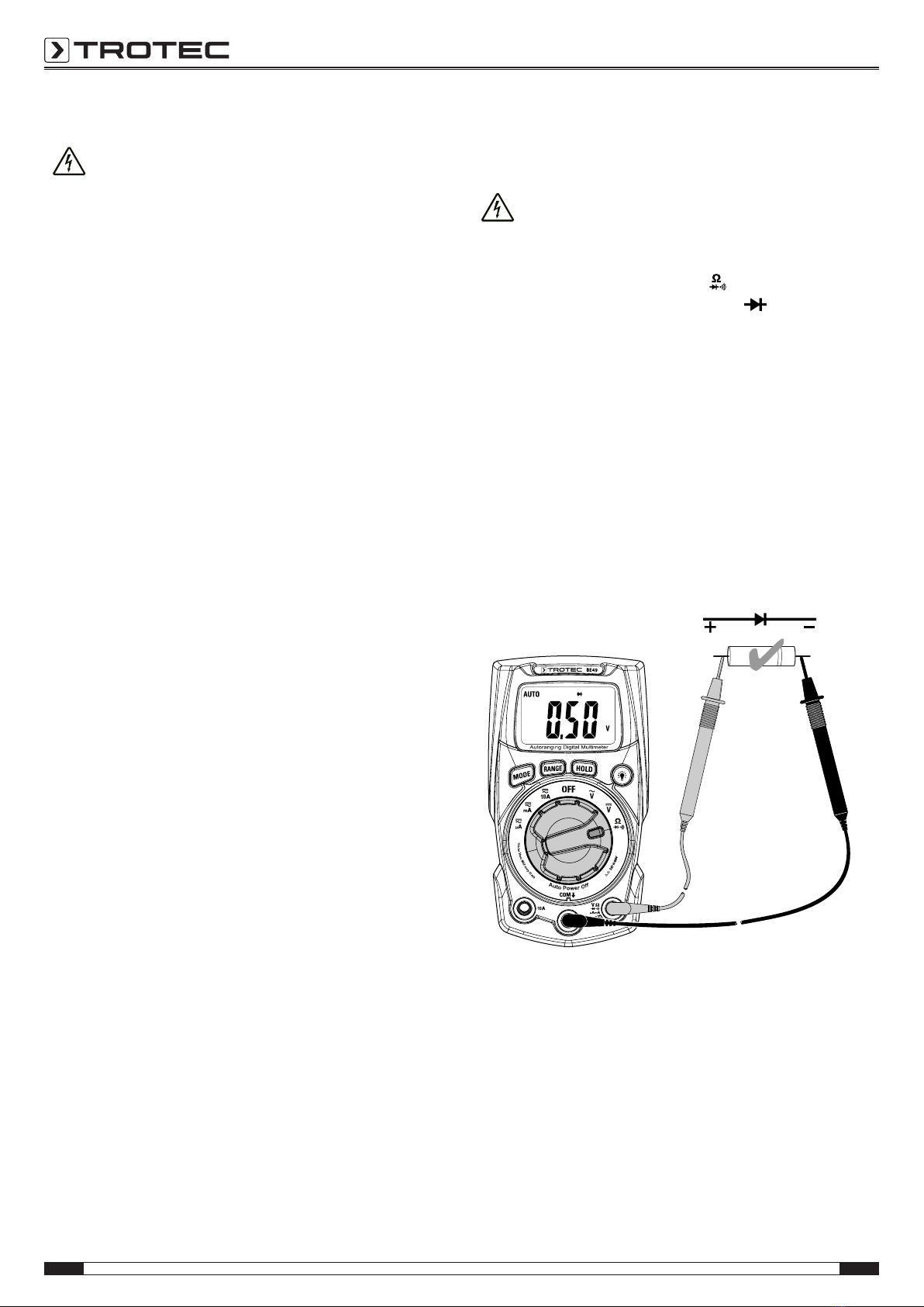
Diode testing
This function permits the testing of semi-conductor paths for
continuity and locking function.
Warning of electrical voltage
Before carrying out resistance, continuity or diode
measurements, switch off the current of the electric
circuit and discharge all capacitors.
1. Set the rotary switch to position and use the
MODEbutton to select the diode test ( indication).
2. Insert the plug of the red measuring tip into the
V/Ωmeasuring socket and the plug of the black measuring
tip into the COMmeasuring socket.
3. Connect the measuring tips to the diode.
The following indications are available:
• OL: wrong polarity– swap the connections of the
measuring tips on the diode
• OL (even after measuring tips have been swapped): open
circuit
• 0.2V to0.7V: the component is working properly (approx.
0.2V for Gediodes and approx. 0.5V in case of Sidiodes).
• Value close to 0mV: circuit is shorted
Other manuals for BE49
1
Table of contents
Other Trotec Multimeter manuals


Popular Multimeter manuals by other brands


Gossen MetraWatt
Gossen MetraWatt METRAmax 6 operating instructions

PeakTech
PeakTech 4000 Procedure of calibration

YOKOGAWA
YOKOGAWA 90050B user manual

Gossen MetraWatt
Gossen MetraWatt METRALINE DMM16 operating instructions

Fluke
Fluke 8846A Programmer's manual

Tempo Communications
Tempo Communications MM200 instruction manual


