1
TROX GmbH
Heinrich-Trox-Platz
D-47504 Neukirchen-Vluyn
Telephone +49/28 45 /2 02-0
Telefax +49/ 28 45/ 2 02-2 65
e-mail trox@trox.de
www.troxtechnik.com
Product Information
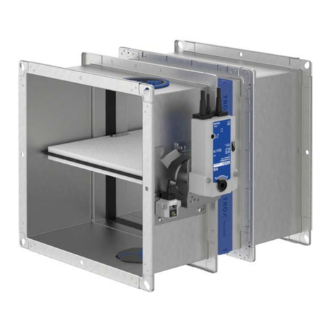
Volume Flow Controller Type EN
Installation, Operation, Maintenance
Installation
When unpacking the controller,
read and take note of
these installation instructions
Design changes reserved · All rights reserved © TROX GmbH (12/2007) · Leaflet no. EØ16KC4
min. 1.5 x B
Product Application
The volume flow controllers type EN are designed for use in
ventilation and air conditioning systems. Only suitably
painted volume flow controllers should be installed in
systems designed to handle aggressive exhaust air, after
thorough testing has been completed.
Safety Measures
Install professionally and support with secure hanging
brackets.
Packaging, Delivery and Storage
The volume flow controllers are packed in disposable
container.
• Check goods immediately after delivery to ensure that
they are complete and have not been damaged during
transportation. Inform the carrier and Trox immediately
if the delivery is incomplete or damaged.
• Do not exposed the controllers directly to the elements
even when packed. Protect from damp, effects of direct
sunlight and dirt.
• Store between –10 ºC bis + 50 ºC.
• Do not remove packing until just before installation.
Installation and Connection Method
• Choose location so that the scales on the controllers
are accessible.
• The desired volume flow can be read and, if necessary,
set, at an external scale.
• Controller operation not dependent on gravity.
• Ensure air flow is in the direction of the arrow on the
label.
• Do not locate controller before bends, near dampers or
other obstructions.
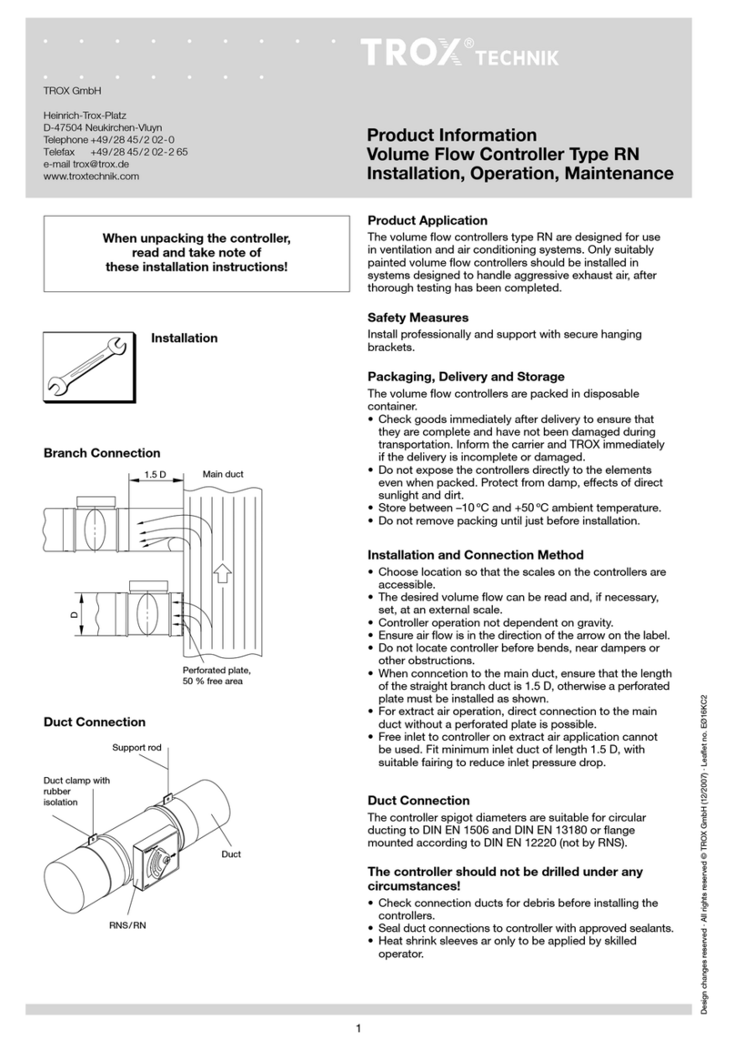
• When connection to the main duct, ensure that the
length of the straight branch duct is 1.5 B. The length of
the straight branch must generally be 0.5 B.
• For extract air operation, direct connection to the main
duct without a perforated plate is possible.
• Free inlet to controller on extract air application cannot
be used. Fit minimum inlet duct of lenght 1.5 B, with
suitable fairing to reduce inlet pressure drop.
Duct Connection
• Check connection ducts for debris before installing the
controllers.
The controller should not be drilled under any
circumstances.
Branch Connection
Duct Connection
B
Main duct
Duct
Support rod
EN
