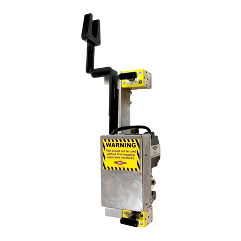
CBS ArcSafe RSA-34 Owner's manual

Published and distributed by:
CBS ArcSafe®
2616 Sirius Road
Denton, Texas 76208
A division of:
GroupCBS, Inc.®
P.O. Box 1557
Gainesville, Texas 76241
Copyright CBS ArcSafe®2019
Printed in the United States of America
Reproduction, adaptation, or translation without prior written permission is prohibited except as is allowed by law.
RSA-34
Installation and Operation
2616 Sirius Road |Denton, TX 76208 |(877) 4-SAFETY |www.cbsarcsafe.com
For GE 7098 MCC
Rev. 3
Distance
is
Safety
®
WE
DO.
WHAT STANDS
BETWEEN YOU AND
ARC-FLASH DANGER?

Published and distributed by:
CBS ArcSafe®
2616 Sirius Road
Denton, Texas 76208
A division of:
GroupCBS, Inc.®
P.O. Box 1557
Gainesville, Texas 76241
Copyright CBS ArcSafe®2019
Printed in the United States of America
Reproduction, adaptation, or translation without prior written permission is prohibited except as is allowed by law.
More Products by CBS ArcSafe®
RRS-1 –Universal Remote Racking System (Rotary)
The CBS ArcSafe® RRS-1 is a universal remote racking system capable of remotely installing and removing rotary style draw
out circuit breakers without requiring any modification to the existing switchgear. Operation of the simple to use RRS-1 is
quite intuitive and requires only minimal setup. When used properly, the RRS-1 allows technicians to remain outside of the
arc flash boundary during the potentially dangerous racking operation.
RRS-2 –Universal Remote Racking System (Non-Rotary)
The CBS ArcSafe® RRS-2 is a universal remote racking system capable of remotely installing and removing non-rotary style
draw out circuit breakers without requiring any modification to the existing switchgear. Operation of the simple to use
RRS-2 is quite intuitive and requires only minimal setup. When used properly, the RRS-2 allows technicians to remain
outside of the arc flash boundary during the potentially hazardous racking operation.
RRS-3 –Application Specific Remote Racking System (Rotary And Non-Rotary)
The CBS ArcSafe® RRS-3 product line is made up of various application specific remote breaker racking devices. Each
standalone system allows service personnel to remotely install and remove a particular type of circuit breaker safely while
stationed safely outside of the arc flash boundary during the potentially dangerous operation. The lightweight and compact
design of the RRS-3 systems makes them ideal for hard to access areas where space is at a premium.
RRS-4 –PLC Based Universal Remote Racking System (Rotary)
The CBS ArcSafe® RRS-4 universal remote racking system is an updated PLC based version of the best selling RRS-1. The
dual mode, source programmable, PLC based control system offers two different operating modes to choose from based on
user preference or the application. The RRS-4 is capable of remotely installing and removing rotary style draw out circuit
breakers without requiring any modification to the existing switchgear, allowing users to remain outside of the arc flash
boundary during the potentially hazardous racking operation.
RSA –Remote Switch Actuator
The CBS ArcSafe® Remote Switch Actuator (RSA) product line is made up of various application specific remote operating
devices. These products allow service personnel to remotely perform all aspects of an operation for a particular type of
electrical equipment from outside the arc flash boundary – reducing or eliminating the possibility of serious injury or death
resulting from an arc flash.
RSO –Remote Switch Operator
During a remote operation, the CBS ArcSafe® RSO functions as both the power supply and user interface for the device
being remotely operated by the user. When paired with an applicable CBS ArcSafe® device, this portable standalone
system allows service personnel to remotely perform a racking or switching procedure from outside the arc flash boundary
– reducing or eliminating the possibility of injury or death resulting from an arc flash
RSA-34
Installation and Operation 3
1Installation
DANGER!
Before servicing any breaker or switch make sure that the nameplate and installed equipment
matches the equipment discussed in this document. If the installed equipment does not
match the equipment described in this document call CBS ArcSafe® for more information.
ATTENTION!
The location of certain items such as mimic bus, stickers, and/or placards may interfere with
the proper installation of the RSA. Please remove or reposition these items before installing
the RSA.
Check the area immediately surrounding the handle operator for obtructions. Any obstructions interfer-
ing with the installation of the RSA-34 may need to be removed or repositioned prior to installation.
Figure 1 - Handle operator with clearance for RSA-34 installation
Jog the RSA-34 motor arm into the correct position based on the current position of the MCC handle op-
erator. If the stops have been properly adjusted, the operator may jog the motor arm until it is resting
flush against the applicable stop, as shown in Figure 2. If the stops have not been adjusted please refer
to Section 3 Adjustment.

RSA-34
Installation and Operation 4
Figure 2 - RSA-34 motor arm jogged into position against hardstop
Once the motor arm has been jogged to the correct position, the RSA-34 may be fitted to the handle op-
erator. Place the RSA-34 over the handle operator and press the device against the switchgear. Ensure
that both magnets sit flush against the cabinet and that the locator on the top side of the RSA fits cor-
rectly over the handle operator’s position indicator as shown in the image below.
Figure 3 - RSA-34 locator in place over position indicator (some parts removed for clarity)
With the RSA-34 properly located on the switch and the magnets sitting flush against the panel, lock the
RSA-34 into position by turning both magnets “ON”. To do this, turn the handle of each magnet 180°
clockwise until it locks into place. The magnets are now turned “ON” and the RSA-34 is secure.

RSA-34
Installation and Operation 5
Next, attach the motor control box to the cabinet in a location where it will not interfere with the opera-
tion of the device. The motor control box has a small magnet located on the bottom side of the box
which is used to attach it to the cabinet.
ATTENTION!
Please ensure that all cables are clear of moving parts. Failure to do so could damage cables
and/or actuator.
The RSA-34 is now installed and ready for operation. Please see the following section for operational in-
structions.

RSA-34
Installation and Operation 6
2Operation
ATTENTION!
Please ensure that all cables are clear of moving parts. Failure to do so may result in damage
to cables and/or actuator.
ATTENTION!
Please ensure that the batteries to the RSO-I AR are fully charged or that the unit is plugged
into AC power.
For detailed instructions on the operation of the RSO-I AR please see the RSO-I AR Manual.
This section will direct users on the proper operation sequence when using the RSA-34 in conjunction
with a CBS ArcSafe RSO-1 AR.
1. Ensure that the RSA is properly installed on the handle operator as described in the previous sec-
tion.
2. With the RSA-34 properly installed, open the RSO-I AR and connect the four pin threaded style
connector from the RSO-1 AR to the RSA-34 motor control box.
3. Power on the RSO-I AR.
4. Exit the arc flash boundary with the RSO-I AR if operating the unit in local mode. If the RSO-I AR is
equipped with the radio remote option, place the RSO-I AR near the RSA and exit the arc flash
boundary with the radio remote.
5. When the operator is safely positioned outside of the arcflash boundary the remote operation
may begin.
6. To close the MCC make sure that the MCC is in the open position. If the MCC is in the open posi-
tion, press and hold the “CLOSE” button on the RSO-I AR to close the MCC.
7. To open the MCC make sure that the MCC is in the closed position. If the MCC is in the closed po-
sition, press and hold the “TRIP” button on the RSO-I AR to open the MCC.
8. To reset the MCC, the hard stop must be adjusted to allow for handle travel past the off position
and into the “RESET” position. Please see the following section regarding RSA-34 adjustments.

RSA-34
Installation and Operation 7
3Adjustments
The RSA-34 has several built in adjustment features which allow it to work with many different styles and
vintages of GE 7098 MCC handle operators. Each of these different adjustments will be highlighted in this
section.
3.1
Travel Adjustment
To adjust the travel of the motor arm of the RSA-34, the adjustable hard stops must be repositioned to
allow for this modified travel range. The following image shows the available adjustment of these stops.
Figure 4 - Travel adjustment of the motor arm
To adjust the stops, loosen the nut and bolt which holds them in place and reposition as necessary. Re-
tighten the nut and bolt after adjustement is complete.
3.2
Height Adjustment
To adjust the height of the RSA-34 motor arm to accommodate different heights of GE 7098 MCC handle
operators please see the following images. Note: the height adjustments on the top and bottom side of
the RSA-34 are independent of one another and are adjusted separately.

RSA-34
Installation and Operation 8
Figure 5 - Height adjustment on the top side of the RSA-34
Figure 6 - Height adjustment on the bottom side of the RSA-34

RSA-34
Installation and Operation 9
3.3
Magnet Location Adjustment
Both the upper and the lower magnet on the RSA-34 may be adjusted side to side to allow for any ob-
structions that may not be moved. The following images will show the side to side adjustment of each
magnet.
Figure 7 - Side to side magnet adjustment on the top side of the RSA-34
Figure 8 - Side to side magnet adjustment on th ebottom side of the RSA-34

RSA-34
Installation and Operation 10
Notes


RSA-34
Installation and Operation
DANGER!
Ensure that personnel using this equipment are adequately trained in the operation of the
switchgear they are planning to work with; that they are correctly stationed outside the arc
flash boundary; and that they comply with all applicable Federal, State, Local, and In-house
safety regulations and procedures. Attention should be given to distance, angle, and person-
al protective equipment (PPE).
2616 Sirius Road
Denton, TX 76208
Tel: 877-4-SAFETY
Fax: 940-382-9435
Website: www.CBSArcSafe.com
Table of contents
Other CBS ArcSafe Controllers manuals

CBS ArcSafe
CBS ArcSafe RSA-138A Owner's manual

CBS ArcSafe
CBS ArcSafe RSK-AK11 User manual

CBS ArcSafe
CBS ArcSafe RSA-104 Owner's manual

CBS ArcSafe
CBS ArcSafe RSA-112 Owner's manual

CBS ArcSafe
CBS ArcSafe RSK-CS01W User manual

CBS ArcSafe
CBS ArcSafe RSK-SPB1 User manual

CBS ArcSafe
CBS ArcSafe RSK-ABL1 Series User manual

CBS ArcSafe
CBS ArcSafe RSA-107 Owner's manual

CBS ArcSafe
CBS ArcSafe RSK-SACE2 User manual

CBS ArcSafe
CBS ArcSafe RSA-138 Owner's manual