Troyka Med T-280 MRI User manual

Troyka Med Inc
IOSB Mah. 2284. Cad No: 48 Yenimahalle Ankara TURKEY
Tel: +90 5325128580- info@troykamed.com –www.troykamed.com
T-280 MRI Conditional Dom Camera Op. Man. Pub. 022018 Pub. No: 0 Rev:0
OPERATORS MANUAL
T-280 MRI Conditional Dom Camera
MRI CONDITIONAL
TO 3 T.0 TESLA

Troyka Med Inc
IOSB Mah. 2284. Cad No: 48 Yenimahalle Ankara TURKEY
Tel: +90 5325128580- info@troykamed.com –www.troykamed.com
T-280 MRI Conditional Dom Camera Op. Man. Pub. 022018 Pub. No: 0 Rev:0
Introduction
Thank you or purchasing the T-280 MRI Conditional Dom Camera. This product is manufactured and
tested to the highest standards and is guaranteed MR Conditional up to 3 Tesla.
This product is manufactured by Troyka Med Inc. at our factory based is Ankara, Turkey, to BS EN
ISO 13485:2016
To ensure that you obtain maximum benefit from the T-280 MRI Dom Camera, please take a few
minutes to read the enclosed information regarding operation, service and maintenance. After
reading this manual, store it in a safe place for future reference.
If you have any problems in the meantime or would like any advice about this or any other MR
products from the Troyka Med range, please contact us at the following address
Troyka Med Inc.
Tel: +90 312 2650096
Website: www.troykamed.com
Protect from
direct sunlight
Protect from rain and
humidity
MRI conditional up to 3 Tesla
Read user manual
Manufacturer
ISO13485
ISO 9001
Class I medical devises

Troyka Med Inc
IOSB Mah. 2284. Cad No: 48 Yenimahalle Ankara TURKEY
Tel: +90 5325128580- info@troykamed.com –www.troykamed.com
T-280 MRI Conditional Dom Camera Op. Man. Pub. 022018 Pub. No: 0 Rev:0
MRI SAFETY DEFINITION FOR MRI AS DEFINED BY
INTERNATIONAL STANDARDS ASTM F2503-13
MR SAFE
An item that poses no known hazards resulting from exposure to any MR
environment MR SAFE items are composed of materials that are electrically
nonconductive, non-metallic, and nonmagnetic.
MR CONDITIONAL
An item with demonstrated safety in the MR environment within defined
conditions. At a minimum, address the conditions of the static magnetic
field, the switched gradient magnetic field and the radiofrequency fields.
Additional conditions, including specific conditions of the item, may be
required.
Supplementary marking –additional information that, in association with
marking as ‘’ MR CONDITIONAL ‘’ states via additional language the
conditions in which an item can be used safely within the MR environment.
MR UNSAFE
An item with poses unacceptable risks to the patient, medical staff or other
persons within the MR environment.
1.2 General Safety Information and Intended Use
The MRI dom camera must only be operated by personnel property trained in MRI safety.
The MRI dom camera must only be operated by personnel properly trained in identifying interference
problems such as artifacts, streaks and distortions in image data. It is required that as personnel handling the
MRI dom camera are familiar with the safety instructions given in the manual and other documentation
provided to ensure safe operation of the camera and associated equipment.
The system comes with a one-year warranty on all parts and labor, and a shelf life on one year starting from
the day of its original installation. Troyka Med Inc. suggests a maintenance call every six months after the
one-year original warranty period to check up on frequently used items such as connection cables and wall
mounts. This way you will make the best use of this system for your facility.
Warning!
If any of the components becomes damaged, stop using the system immediately and
notify Troyka Med Inc. customer service for assistance. Use of broken components
can cause injury to the clinician or the patient.

Troyka Med Inc
IOSB Mah. 2284. Cad No: 48 Yenimahalle Ankara TURKEY
Tel: +90 5325128580- info@troykamed.com –www.troykamed.com
T-280 MRI Conditional Dom Camera Op. Man. Pub. 022018 Pub. No: 0 Rev:0
1.3 Electrical safety
Warning!
Contain electric components in the device require several hundred volts to operate properly.
In order to prevent potentially lethal electric shock it is essential to disconnect the device from
its power source during installation, and prior to servicing or repair. Some capacitors will
remain charged with dangerous voltage levels even after the power is off. In order to prevent
any possible electric shock, please wait several minutes for all capacitors to become
completely discharged before proceeding.
Warning!
Do not operate the device near the water, where it can become moist, or near
excessive heat. Operation under such conditions could result in failure of the dom
camera, possible electric shock, or fire. Don’t handle the power cable with wet hands.
High voltages present could cause lethal electric shock.
Warning!
Should any foreign substances enter the device such as liquid, metal chips or dust,
immediately turn off power to the Interface Unit. Under no circumstances shall tools
or foreign objects be inserted into the device, as this could result in failure of the
device, electric shock or fire.
Warning!
If smoke, noxious odors or unusual noise should come from the device, immediately
turn off power to the dom camera and contact your local distributor or Troyka Med
service team.
Warning!
Do not damage the power cable of the device. Do not attempt to modify the power
cable should it malfunction. Should the power cable become damaged or frayed, it
must be replaced.
Warning!
Do not operate the camera system if any cables are damaged.
Warning!
Switch off and unplug the Sound System if it not be in use for 1 days or more.
Warning!
To avoid the risk of electric shock, this equipment must only be connected to supply
mains with protective earth.

Troyka Med Inc
IOSB Mah. 2284. Cad No: 48 Yenimahalle Ankara TURKEY
Tel: +90 5325128580- info@troykamed.com –www.troykamed.com
T-280 MRI Conditional Dom Camera Op. Man. Pub. 022018 Pub. No: 0 Rev:0
Warning!
Self-heating of cables due to improper cable routing! Injury to equipment and/or
operating personnel. Cables should not be looped crossed inside MRI room.
1.4 Warnings for MRI
Caution!
Installation of materials inside the MRI must be done with extreme caution.
Caution!
Take care that ferromagnetic materials be kept at least three meters away from the
magnet and that no installation shall be done near the filter panel if a scan is in
progress.
Caution!
In addition, no persons with ferromagnetic prosthetic devices, such as pacemakers or
joints replacement, should enter the MRI suite at any time. Extreme, high magnetic
fields inside the magnetic room have the potential to dislodge items at high velocities
and can result in serious injury, or death.
Caution!
For questions regarding installation procedures or technical support, call Troyka Med
Service team or contact via email at info@troykamed.com.
Caution!
Only system components explicitly designed for use inside the MRI suite should be
placed inside the magnet room. Components not designed for MRI use may present a
projectile hazard and can become airborne, causing serious injury, damage or death.
2 General Information
2.1. Inspection of Delivered Goods
Each of MRI dom camera has been thoroughly tested prior to deliver and is ready for immediate use. Upon
receipt, please report any transportation damage or missing accessories immediately. Troyka Med can only
accept liability for such damages if it is claimed prior to initial operation. In case of transportation damage,
please contact the Troyka Med service department. For faster support please have ready all shipment details
Troyka Med Inc
IOSB Mah. 2284. Cad No: 48 Yenimahalle Ankara TURKEY
Tel: +90 5325128580- info@troykamed.com –www.troykamed.com
T-280 MRI Conditional Dom Camera Op. Man. Pub. 022018 Pub. No: 0 Rev:0
dom camera serial number and damage description. It is recommended to keep and store the original
crate/box used to ship the com camera for all future transportation needs.
2.2 Power Connection Information
The MRI dom camera operates on the line voltages 90-250V AC and 50/60 Hz. It is not necessary to double
check line voltages or change any fuses. The equipment should be near the power outlet in the technical
room of MRI and the outlet should be easily accessible.
Stabilizing circuits ensures satisfactory performance within supply variations specified. If the supply voltage
in your location is not 90-250V AC, please consult your Troyka Med Sales or Service office.
Always use the power supply cord supplied in the original shipping carton.
If the enclosed power cord could not be used due to a different standard in your country, use a power cord
that conforms to the fallowing regional standards:
United States (UL)
United Kingdom (BASEC/BS)
Germany (VDE)
Switzerland (SEV)
Canada (CSA)
Japan (MITI)
In other regions, please use an AC power cord that complies with the country’s safety regulations.
In order to prevent electrical hazard, the cord set must use a three-core cable of at least 6A/0.75mm2, and
have an earth ground contact on both the free socket and the plug. If the main cord is damaged, use only an
original replacement cable.
3 System Overview and Installation Guide
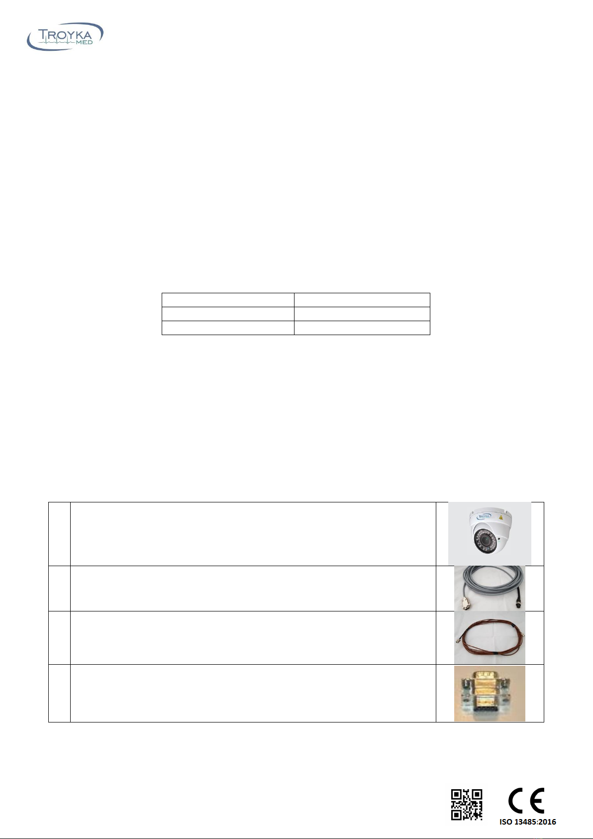
3.1 Parts Included
1
MRI conditional dome camera
2
MRI room power cable (10m cable)
Please contact for other length requirements.
3
MRI room coaxial cable (10 m cable )
Please contact for other length requirements.
4
MRI Filter: 9 Pin D-Sub LPF with EMI gasket
Troyka Med Inc
IOSB Mah. 2284. Cad No: 48 Yenimahalle Ankara TURKEY
Tel: +90 5325128580- info@troykamed.com –www.troykamed.com
T-280 MRI Conditional Dom Camera Op. Man. Pub. 022018 Pub. No: 0 Rev:0
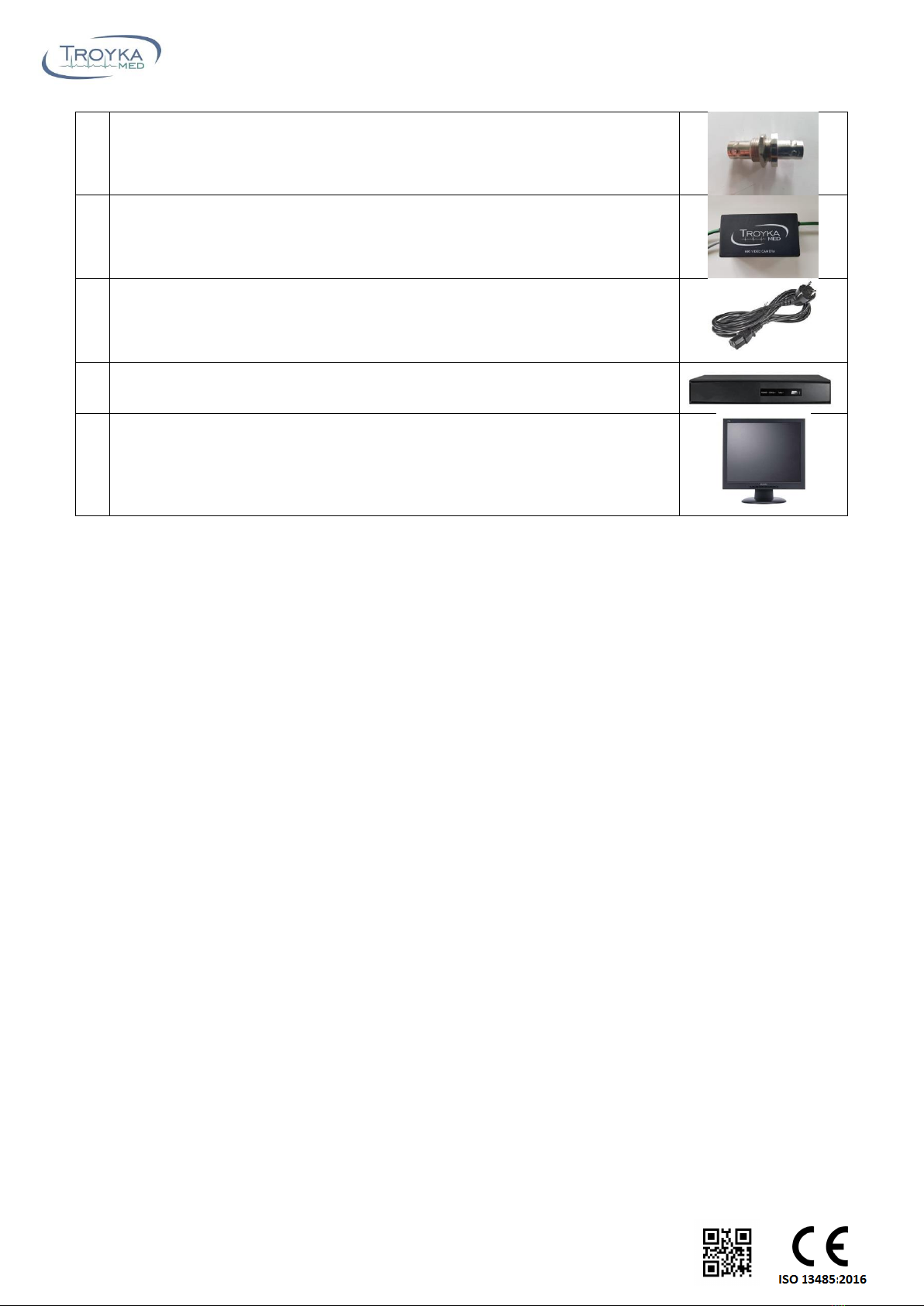
5
MRI BNC filter
6
Dom camera interface box (with 30 m coaxial cable)
Please contact for other length requirements.
7
Power cable
8
DVR unit
9
Monitor: 17‘’ LED monitor
Please contact for other options.
Table 1: MRI dom camera system list of components
3.2 System Overview
Our MRI compatible cameras are designed to view and record video images of objects in an MR scanner. The
camera can be used to view patient in MRI scanner or overview MRI room.
The T-280 MRI Dom Camera System is designed to be MRI conditional and is manufactured and tested to the
highest standards. The camera system is designed to be used with all MRI scanners up to 3 Tesla magnetic
field strength.
A picture of MRI conditional dom camera is given in Figure 1. The camera can be used both on the wall or
ceiling mount position and the angle of view could be adjusted to any possible position. The camera has 2.8-
12 mm varifocal lens. This high focus capability of the camera gives users an ability to focus camera to any
desired position even from long distance. The zoom and focus adjustments could be done via two
adjustment screws shown in Figure 1. Embedded IR LED provide high image quality even in a low light
environment. 2 MP sensor provides high image quality.

Troyka Med Inc
IOSB Mah. 2284. Cad No: 48 Yenimahalle Ankara TURKEY
Tel: +90 5325128580- info@troykamed.com –www.troykamed.com
T-280 MRI Conditional Dom Camera Op. Man. Pub. 022018 Pub. No: 0 Rev:0
Figure 1: MR conditional dome camera.
3.3 Technical Specification
Camera
Resolution
1920 x 1080 2MP
Lens
2.8-12mm VF
IR LED - IR Cut
36 LED /25 m –Automatic
Standard
AHD
Operation Voltage
DC 12V /1A
Minimum Lighting
0.01Lux@; F1.2/AGC ON
Electronic Parameter
1/25s;1/100,000s
25fps @1080p –30fps @1080P
High speed, long distance, real time transmission
Full HD and standard definition switch
Day/night (ICR), 3D-DNR
3.4 Installation
3.4.1 Installation Diagram of MRI Video Camera in Magnet Room
A representative drawing is showing the layout plan of the MRI video camera is given in Figure 2. The camera
shown in Figure 2-1 depending on the customer requirement could be installed to any place inside MRI
room. The detailed installation procedure of the camera is described in section 3.4.2. The video signal cable
Zoom adjustment
Focus adjustment
IR LED
2.8-12 mm varifocal lens

Troyka Med Inc
IOSB Mah. 2284. Cad No: 48 Yenimahalle Ankara TURKEY
Tel: +90 5325128580- info@troykamed.com –www.troykamed.com
T-280 MRI Conditional Dom Camera Op. Man. Pub. 022018 Pub. No: 0 Rev:0
and 9 pin cable shown in the Figure 2-2 and 3 must be connected to the penetration panel. Most of the MRI
scanners has BNC and 9 pin filters available on the penetration panel. If there is no available filter on your
penetration panel use the ones included in your package (Table 1- 4 and Table 1-5).
The interface box must be placed in the cabinet room. The female 9 pin connector of the interface box must
be connected to the male connector of the 9-pin filter (Figure 2-5) of the penetration panel the video signal
cable must be connected to the BNC filter. The power cable of the interface box must be connected to the
power outlet. The 30m video signal cable of the interface box must be connected to the video processing
unit in operation room. Using VGA cable connects the video interface unit to the monitor and the system will
be ready to use.
In order to power on the camera, turn on the power switch which is available on the interface unit (Figure 2-
9).
Figure 2: MR conditional dome type video camera installation diagram.
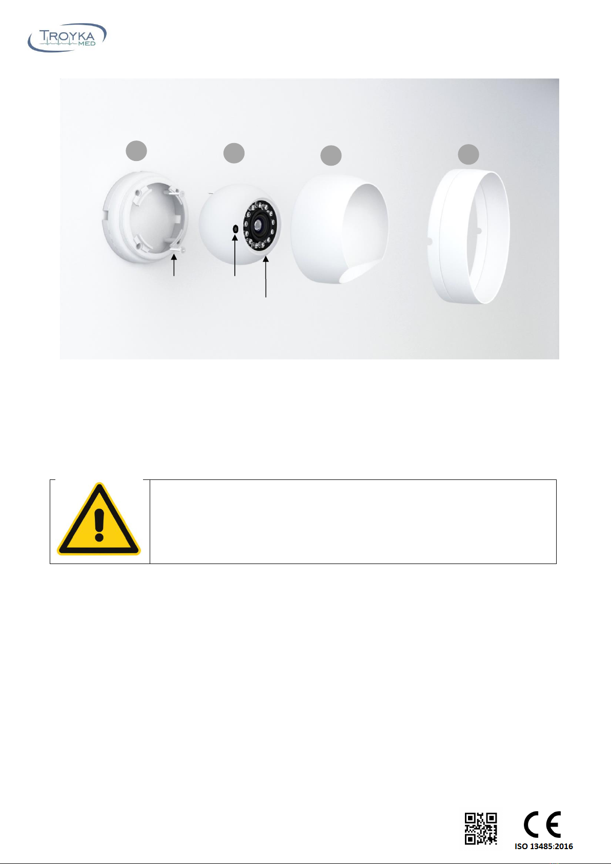
3.4.2. MRI Camera Installation diagram
The representative drawing showing the installation diagram of the MRI camera is given in Figure 3. Use 4
screws delivered in the package to mount the base part of the camera (Figure 3-1) to the wall as is shown in
Figure 3. After that, place the camera into the base and put the component 3 (figure 3-3) over the camera
then place on the component 4 on whole assemble and screw it. Adjust proper direction of the camera and
tighten the component not to let camera move.
Adjust the focus and zoom settings of the camera. For the adjustment use thin flat screwdriver. Place the
screwdriver into the zoom or focus hole that is shown on the figure 3-5. Screwing it adjust the desired zoom
and focus setting for optimal image quality.
1. MRI Camera
2. Video signal
cable
3. 9 Pin cable
4. BNC Filter
5. 9 pin filter
2. Video signal
cable
3. 9 Pin cable
Power Outlet
6. Interface Box
2. Video signal
cable
7. Video converter unit
8. Monitor
Magnet Room
Cabinet Room
Operator Room
9. Power Switch
Troyka Med Inc
IOSB Mah. 2284. Cad No: 48 Yenimahalle Ankara TURKEY
Tel: +90 5325128580- info@troykamed.com –www.troykamed.com
T-280 MRI Conditional Dom Camera Op. Man. Pub. 022018 Pub. No: 0 Rev:0
4. Maintenance and Disposal
4.1 Cleaning Information
Dust and other matter that collect on the camera may eventually degrade image quality. Such matter should
be removed from the top of the camera with a damp cloth.
Warning
Unplug all power connections before cleaning.
4.1.1. Monitor Surface
Dampen (do not saturate) a clean, lint-free cloth with environmentally friendly glass cleaner. The cleaner
contains spirit as an active substance (up to 98%) and tensides, which can be biologically recycled. Cline the
monitor screen using circular motions with the cloth to avoid streams. Remove fingerprints, grease, dirt, and
dust. Carefully dry the screen with a second, lint-free cloth.
4.1.2. Camera Surface and wires
Use a cloth with disinfectant to clean the camera body and wires. Remove fingerprints, dirt, grease and dust.
1
2
3
4
Screws
Zoom
Focus
Table of contents
Popular Security Camera manuals by other brands


Bosch
Bosch REG-D1-875XE-01 installation instructions

Vivotek
Vivotek IT9389 Series user manual

Speco
Speco CVC-6146HR Operation & installation manual

Sony
Sony Ipela SNC-DH210T Specifications

SECO-LARM
SECO-LARM Enforcer EV-122C-DVC3 Specification sheet

Larson Electronics
Larson Electronics EXPCMR-WIP-RPS-OZ-2MP-BC instruction manual


