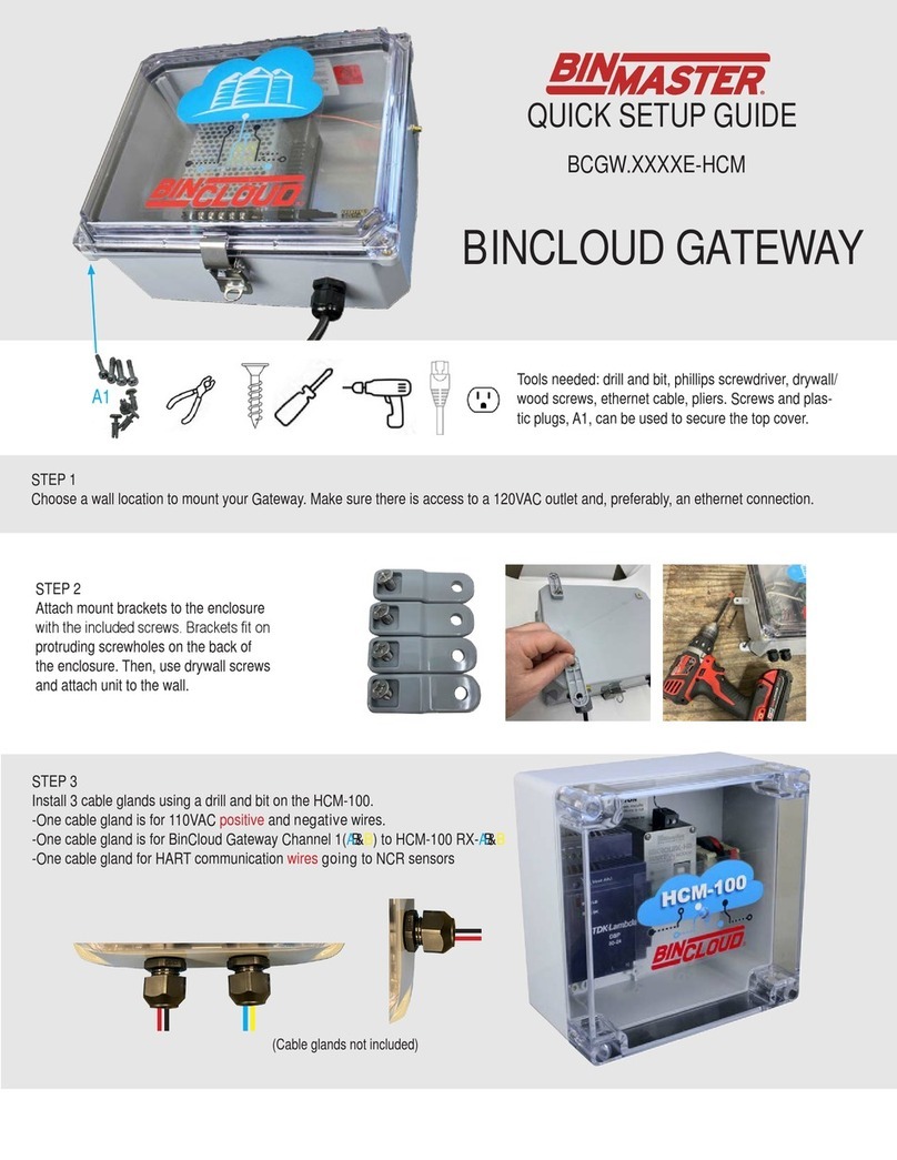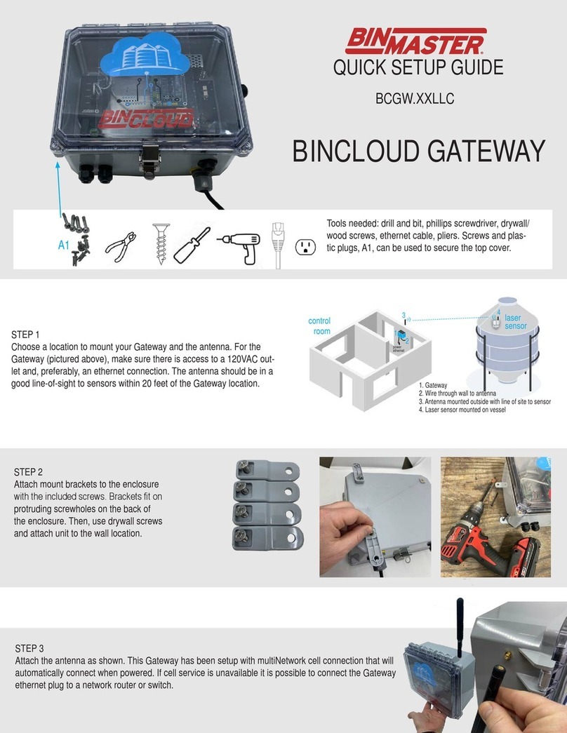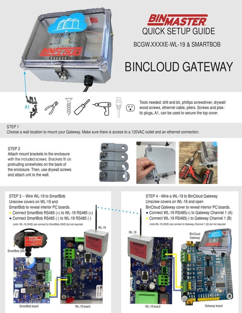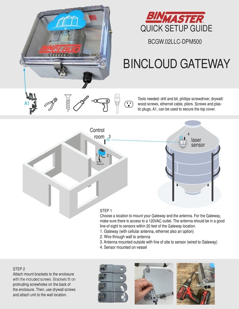
Tools needed: drill and bit, phillips screwdriver, drywall/
wood screws, ethernet cable, pliers. Screws and plas-
tic plugs, A1, can be used to secure the top cover.
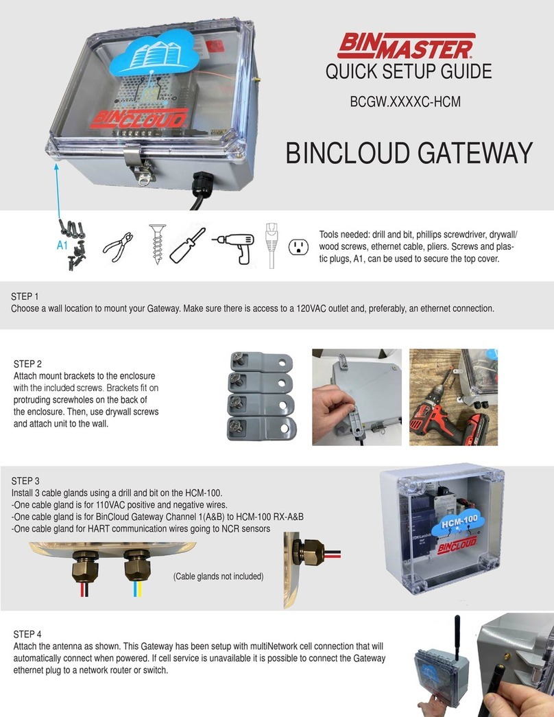
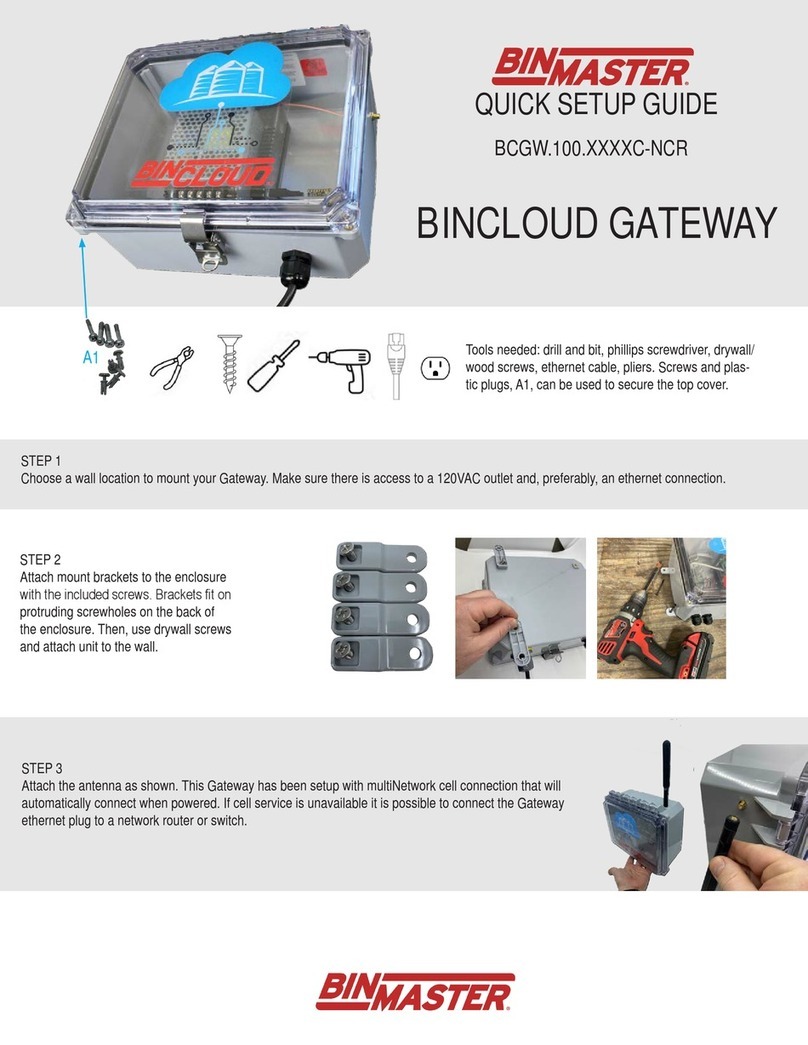
STEP 2
Attach mount brackets to the enclosure
with the included screws. Brackets t on
protruding screwholes on the back of
the enclosure. Then, use drywall screws
and attach unit to the wall location.
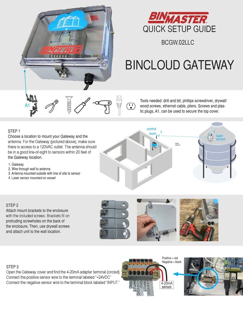
STEP 3 FOR 4-20mA SENSORS
(Modbus sensors skip to STEP 3.1)
Open the cover and nd the 4-20mA adapter terminal (circled).
Connect the positive sensor wire to the terminal labeled “+24VDC”
Connect the negative sensor wire to the terminal block labeled “INPUT”.
Ground wires go to “GND”.
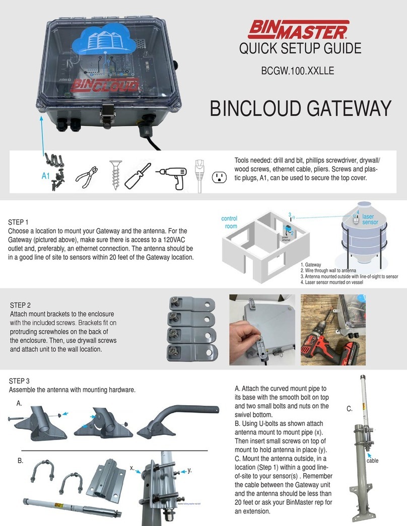
STEP 1
Choose a wall location to mount your Gateway. Make sure there is access to a 120VAC outlet and, preferably, an ethernet connection.
A1
QUICK SETUP GUIDE
BINCLOUD GATEWAY
BCGW.02XXE
Wiring for a 2-wire sensor,
powered by the current loop
4-20mA
sensor
Wiring for a 3-wire sensor,
powered by Yocto-4-20mA-Rx
(max 80mA)
4-20mA
sensor
Wiring for a 4-wire sensor, with an
independent power supply.
4-20mA
sensor
Power
source
4-20mA
sensor
Power
source
Wiring for 3-wire sensor, with
independent power supply with
common ground.
Base photo of Gateway. Some units include extra terminals.
925-0413 02/13/2023
