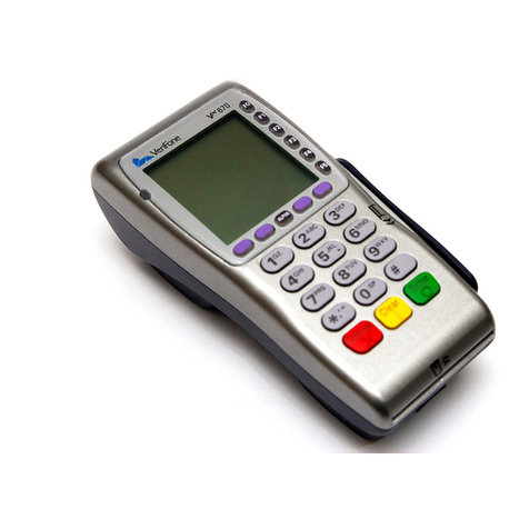
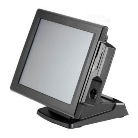
True Value RockSolid POS User manual

RockSolid POS
EQUIPMENT INSTALLATION INSTRUCTIONS
In preparation for your initial Installation Call, you will
need to follow these instructions in a specific order.
¾Make sure you received all the equipment by checking it against the packing list.
¾If anything is missing please contact your Retail Systems sales representative immediately.
¾If you have any questions regarding these instructions please contact your Help Desk at
1-800-882.1137 and they will direct your call to the appropriate person.
This document was updated on December 8, 2005.

True Value Company
- 2 - RockSolid Equipment Installation Instructions_beta
PREPARATION
These instructions will walk you through setting up your primary POS PC/Server, and a second PC
which will be used as an office workstation.
NOTE: Do not unpack anything before reading the installation procedure. The
installation procedure needs to be performed in a specific order.
After you have read the installation procedure, you should unpack and remove everything from the
box.
However, you will need to assemble the RockSolid components in the following order:
1. Battery Backup (UPS)
2. Cash Drawer
3. POS Server PC
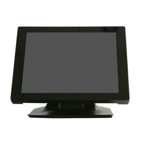
4. Monitors
5. Barcode Scanner
6. Signature Capture Pad
7. Receipt Printer
8. Credit card swipe (Optional)
9. Display Pole (Optional)
10. Workstation PC
11. Dymo Label Printer
12. REV Backup Drive

True Value Company
RockSolid Equipment Installation Instructions_beta - 3 -
TABLE OF CONTENTS
BATTERY BACKUP ............................................................................................................... 4
Connect the Battery......................................................................................................... 4
Charge the Battery........................................................................................................... 5
Connecting Equipment to the Back-UPS ........................................................................ 5
Battery Back-Up Outlets........................................................................................... 5
Surge Only Outlets.................................................................................................... 5
NETWORK SET UP................................................................................................................. 6
Ethernet Wiring Diagram (CAT 5e Cable)...................................................................... 8
POS / SERVER SET UP........................................................................................................... 9
Cash Drawer.................................................................................................................... 9
Primary POS/PC Server .................................................................................................. 9
Monitor.......................................................................................................................... 10
Receipt Printer............................................................................................................... 11
Barcode Scanner............................................................................................................ 12
Signature Capture Pad................................................................................................... 13
Credit Card Swipe ......................................................................................................... 14
Display Pole .................................................................................................................. 15
BACK OFFICE WORKSTATION INSTALLATION........................................................... 16
Back Office Workstation............................................................................................... 16
Monitor.......................................................................................................................... 17
Dymo Label Printer....................................................................................................... 18
REV Backup Drive........................................................................................................ 18

BATTERY BACKUP True Value Company
BATTERY BACKUP
In compliance with Department of Transportation (DOT)
regulations, the Back-UPS is shipped with the internal red
battery wire disconnected.
The Back-UPS will not operate until the internal red wire is
connected to the battery.
Connect the Battery
1. Note the yellow warning sticker on the side of the battery backup.
2. Open the battery compartment, as shown.
3. Pull the battery about half way out, as shown.
4. Connect the red battery wire to the positive battery terminal.
5. Small sparks may occur during battery connection. This is normal.
6. Push the battery into the battery compartment and re-install the
cover, as shown.
- 4 - RockSolid Equipment Installation Instructions_beta

True Value Company BATTERY BACKUP
RockSolid Equipment Installation Instructions_beta - 5 -
Charge the Battery
During normal operation, the Back-UPS charges the internal battery any time it is connected to a
wall outlet.
1. Once connected, allow the Back-UPS to charge for a full
eight hours.
2. While the Back-UPS receives its initial charge, you may
continue with the Network Setup part of the installation.
Connecting Equipment to the Back-UPS
The rear panel of the Back-UPS consists of:
¾Battery Back-Up Outlets
¾Surge Only Outlets
Battery Back-Up Outlets
Battery Back-Up outlets are typically used for a computer, monitor, and external disk or CD-ROM
drive. Battery Back-Up outlets provide battery back-up, surge protection, and Electro-magnetic
Interference (EMI) filtering. During a power outage, battery power is automatically provided to
these outlets. Power is not supplied to these outlets when the Back-UPS is switched OFF.
Surge Only Outlets
Surge Only outlets are typically used for a printer, fax machine, or scanner. Surge Only outlets are
always ON when utility power is available and are not controlled by the On/Off switch. These
outlets DO NOT provide power during a power outage.

NETWORK SET UP True Value Company
NETWORK SET UP
- 6 - RockSolid Equipment Installation Instructions_beta

True Value Company NETWORK SET UP
RockSolid Equipment Installation Instructions_beta - 7 -
You will be required to set up your in-store network.
If you do not feel you have the expertise for this, then we
recommend that you hire a local specialist who can
troubleshoot your network in case you run into any difficulties
down the road.
1. You will need to acquire a high-speed Internet connection. This can be either a DSL
connection or a Broadband Cable connection.
2. The network must be run with either CAT5e UTP (Unshielded Twisted Pair) or CAT6 UTP
Ethernet wire.
¾You can purchase the Ethernet wire in precut lengths with connectors attached through
your Retail Systems Sales Representative.
¾You can purchase bulk Ethernet wire without connectors attached. 1000 foot rolls of bulk
wire are available through the warehouse using item number 608155. However, if you
order in bulk lengths, you will need to assemble your own connectors. (See the topic
called Ethernet Wiring Diagram.)
3. You will have to run a cable from each PC to the network hub (or router).
4. The maximum length of each cable cannot exceed 328 feet. The cable ends must be pinned
according to wiring standard 568-B. (See the topic called Ethernet Wiring Diagram.)
5. The Ethernet cable should be run at least 12” from any electrical cable or fluorescent lighting.
If you must cross either of these, it should be done perpendicular to the cable or lighting
fixture. In other words, at a right angle (90 degrees).
6. Use the following naming convention for the PC’s:
¾Workgroup Name: RockSolid
¾Pos Stations: RPOSX (X= register letter A, B etc.)
¾Work Stations: RWSX (X= register letter A, B etc.)
¾Server Pos Stations: RPSERVERX (X= register letter A, B etc.)
¾Server Work Stations: RWSERVERX (X= register letter A, B etc.)
7. The network should not contain static IP addresses.
8. We recommend using a DHCP router to assign IP addresses automatically. The router should
be labeled with:
¾IP address
¾Username
¾Password
9. Place the label on the bottom of the router.

NETWORK SET UP True Value Company
Ethernet Wiring Diagram (CAT 5e Cable)
CAT5e Cable is short for Category 5e cable. Cat5e cable is network cabling consisting of four
twisted pairs of copper wire terminated by RJ45 connectors.
¾Cat 5e cabling supports frequencies up to 350 MHz and speeds up to 1000 Mbps.
¾Solid CAT5e cable supports long cable runs and is designed for fixed cabling situations
like homes, offices, and buildings. The maximum length of each cable is 328 feet.
1. If you order CAT 5e cable in bulk lengths, you will need to assemble your own connectors
according to wiring standard 568-B as shown below.
2. Using a stripping tool, strip the cable jacket slightly more than one inch.
3. Untwist each pair of wires back to within 1/8" of the cable jacket.
4. Using your fingers, straighten each wire.
5. Utilizing the 568B diagram shown above, place the wires in the order displayed.
6. Bring all of the wires together, until they touch.
7. Recheck the wiring sequence with the 568B diagram shown above.
8. Grasp the wires firmly, between your thumb and forefinger, flatten them, and even wiggle
them a bit, to take out the curliness. The wires must lay flat and together, aligned as close as
possible.
9. While holding the wires firmly, cut off the wires 1/2" from the cable jacket. This is a very
critical step. If the wires are not cut straight, they may not all make contact into the connector.
10. You should cut the wires with some sharp wire strippers or even high quality scissors. You
need to avoid wire cutters that flatten the ends of the wires. This makes stuffing the wires very
difficult.
11. You must cut all of the wires at a perfect 90 degree angle from the cable at 1/2" from the end of
the cable jacket.
12. Stuff the wires into the connector, making sure the wires stay lined up.
13. Push moderately hard to assure that all of the wires have reached the end of the connector. Be
sure that the cable jacket goes into the back of the connector by about 3/16".
14. Place the connector into a crimp tool, and squeeze hard so that the handle reaches its full
swing.
15. Repeat the process on the other end.
16. Use a cable tester to test for proper continuity.
- 8 - RockSolid Equipment Installation Instructions_beta

True Value Company POS / SERVER SET UP
RockSolid Equipment Installation Instructions_beta - 9 -
POS / SERVER SET UP
Cash Drawer
1. Unpack the cash drawer.
2. Be careful when removing the packing material because
there is a special cable enclosed in the box. It looks like a
heavy duty phone cord. Make sure you remove it also.
3. Place the cash drawer in the appropriate spot and connect
the end of the cable marked MMF P/N into the port in the
back of the cash drawer.
Primary POS/PC Server
1. Unpack the computer, keyboard, mouse, and power cable.
2. Set the POS/Server PC in place.
3. Plug the Power Cable from the back of the PC into the
battery backup side of the Back-UPS.
4. Do not turn on the PC at this point.
5. On the rear of the POS/Server PC, connect the Network,
Keyboard, and Mouse cables:
Plug in the Network Cable to network
connection port.
Plug in the Mouse to the USB port on
the back of the PC below the network
connection port.
Plug in the Keyboard to the USB port
on the back of the PC below the
Mouse USB port.

True Value CompanyPOS / SERVER SET UP
Monitor
1. Unpack the monitor.
2. Set the monitor on top of the PC.
3. Connect the Power Cable to the back of the monitor.
4. Plug the Power Cable into the battery backup side of the
UPS.
5. Do not turn on the monitor.
6. Connect the Special Adapter into the video port on the
back of the PC.
7. Connect the monitor video cable into the Special Adapter.
8. Connect the network cable from the back of the PC (as
shown) to the switch.
9. Verify that the UPS is turned on.
10. Turn on the monitor and the PC.
11. You may get a message indicating that the system has
“Found New Hardware” and that the system asks you to
“Insert a Disk.”
12. Be sure to cancel any “Found New Hardware” messages
that prompt you to continue or “Insert a Disk.”
- 10 - RockSolid Equipment Installation Instructions_beta

True Value Company POS / SERVER SET UP
RockSolid Equipment Installation Instructions_beta - 11 -
Receipt Printer
The Receipt Printer and its Power Supply are packaged in separate boxes.
1. Unpack both the Receipt Printer and its Power Supply.
2. Connect the Power supply to the port on the back of the
printer.
3. Connect the Power cord to the power supply.
4. Connect the Parallel printer cable to the back of the receipt
printer.
5. Connect the Cable from the back of the cash drawer to the
back of the receipt printer.
6. Install a roll of paper as illustrated.
7. Plug power cable into the surge protected side of the UPS.
8. Do not turn on the printer.

True Value CompanyPOS / SERVER SET UP
Barcode Scanner
The scanner consists of several parts, the scanner a coiled cable and the stand.
1. Assemble the stand according to the scanner instructions.
2. Locate the stack of 4 USB connections on the rear of the
PC.
3. Connect the scanner to the bottom USB port of the stack as
shown.
- 12 - RockSolid Equipment Installation Instructions_beta

True Value Company POS / SERVER SET UP
RockSolid Equipment Installation Instructions_beta - 13 -
Signature Capture Pad
1. Remove Signature Capture Pad from the
packing. It is already assembled.
2. Be sure to place spare batteries for the
stylus in a safe place.
3. Locate the stack of 4 USB connections on
the rear of the PC.
4. Connect the Signature Capture Pad to the
USB port located third from the top of the
stack as shown.

True Value CompanyPOS / SERVER SET UP
Credit Card Swipe
The Credit Card Swipe is an optional piece of equipment. It will be provided if you are processing
credit cards through RockSolid.
1. Unpack the Credit Card Swipe.
2. Mount the Credit Card Swipe to the desired location that
you wish to use for this purpose. Some suggestions
include: On the side of the monitor, on top of the cash
drawer, etc.
3. Locate the stack of 4 USB connections on the rear of the
PC.
4. Connect the Credit Card Swipe to the USB port located
second from the top of the stack as shown.
- 14 - RockSolid Equipment Installation Instructions_beta

True Value Company POS / SERVER SET UP
RockSolid Equipment Installation Instructions_beta - 15 -
Display Pole
The Display Pole is an optional piece of equipment.
1. Unpack the display pole.
2. Assemble it according to the instructions enclosed with the
Display Pole.
3. Connect the power cord to the USB cable.
4. Locate the stack of 4 USB connections on the rear of the
PC.
5. Connect the Display Pole to the USB port located at the top
of the stack as shown. The top port should always be used.
6. You may get a message indicating that the system has
“Found New Hardware” and that the system asks you to
“Insert a Disk.”
7. Be sure to cancel any “Found New Hardware” messages
that prompt you to continue or “Insert a Disk.”
8. In the future, if you should move the computer, then the
display pole cable must be plugged into the top port.

True Value CompanyBACK OFFICE WORKSTATION
BACK OFFICE WORKSTATION INSTALLATION
A Back-UPS is not required for the Back Office Workstation. At the very least, you should use a
surge protected multiple outlet power strip. However, for Best Practices, you should always use a
Back-UPS on any PC.
Back Office Workstation
1. Unpack the computer, keyboard, mouse, and power cable.
2. Set the Back Office Workstation PC in place.
3. Plug the Power cable from the back of the Back Office
Workstation PC to the surge protected multiple outlet
power strip or into the battery backup side of the Back-
UPS.
4. Do not turn on the Back Office Workstation PC at this
point.
5. On the rear of the Back Office Workstation PC, connect the Network, Mouse, and Keyboard
cables:
Plug in the Network Cable to network
connection port.
Plug in the Mouse to the USB port on
the back of the PC below the network
connection port.
Plug in the Keyboard to the USB port
on the back of the PC below the
Mouse USB port.
- 16 - RockSolid Equipment Installation Instructions_beta

True Value Company BACK OFFICE WORKSTATION
RockSolid Equipment Installation Instructions_beta - 17 -
Monitor
1. Unpack the monitor.
2. Set the monitor on top of the PC.
3. Connect the Power Cable to the back of the monitor.
4. Plug the Power Cable into the battery backup side of the
UPS.
5. Do not turn on the monitor.
6. Connect the Special Adapter into the video port on the
back of the PC.
7. Connect the monitor video cable into the Special Adapter.
8. Connect the network cable from the back of the PC (as
shown) to the switch.
9. Verify that the surge protected multiple outlet power strip
or Back-UPS is turned on.
10. Turn on the monitor and the PC.
11. You may get a message indicating that the system has
“Found New Hardware” and that the system asks you to
“Insert a Disk.”
12. Be sure to cancel any “Found New Hardware” messages
that prompt you to continue or “Insert a Disk.”

True Value CompanyBACK OFFICE WORKSTATION
Dymo Label Printer
1. Unpack and assemble the Dymo Label Printer.
2. Do not connect it to the Back Office Workstation PC.
REV Backup Drive
1. Unpack and assemble the REV Backup Drive.
2. Do not connect it to the Back Office Workstation PC.
- 18 - RockSolid Equipment Installation Instructions_beta
Table of contents
